Table of Contents
Advertisement
. . . . . . . . . . . . . . . . . . . . . . . . . . . . . . . . . . . . . . . .
. . . . . . . . . . . . . . . . . . . . . . . . . . . . . . . . . . . . . . .
Timers
. . . . . . . . . . . . . . . . . . . . . . . . . . . . . . . . . . . . . . . . . . . . . . . .
. . . . . . . . . . . . . . . . . . . . . . . . . . . . . . . . . . . . . . . . . . . .
. . . . . . . . . . . . . . . . . . . . . . . . . . . . . . . . . . . . . . . . . . . .
. . . . . . . . . . . . . . . . . . . . . . . . . . . . . . . . . . . . . . . . . . . .
. . . . . . . . . . . . . . . . . . . . . . . . . . . . . . . . . . . . . . . . . . . . . . . . .
. . . . . . . . . . . . . . . . . . . . . . . . . . . . . . . . . . . . . . . . . . . . . .
. . . . . . . . . . . . . . . . . . . . . . . . . . . . . . . . . . . . . . . . . . . . . . . . . .
. . . . . . . . . . . . . . . . . . . . . . . . . . . . . . . . . . . . . . . . . . . . . . . . .
. . . . . . . . . . . . . . . . . . . . . . . . . . . . . . . . . . . . . . . . . . . . . . . . . .
. . . . . . . . . . . . . . . . . . . . . . . . . . . . . . . . . . . . . . . . . . . . . . . . .
. . . . . . . . . . . . . . . . . . . . . . . . . . . . . . . . . . . . . . . . . . . . . . . . .
. . . . . . . . . . . . . . . . . . . . . . . . . . . . . . . . . . . . . . . . . . . . . . . . .
. . . . . . . . . . . . . . . . . . . . . . . . . . . . . . . . . . . . . . . . . . . . . . . . .
. . . . . . . . . . . . . . . . . . . . . . . . . . . . . . . . . . . . . . . . . . . . . . . . .
. . . . . . . . . . . . . . . . . . . . . . . . . . . . . . . . . . . . . . . . . . . . . . . . . .
. . . . . . . . . . . . . . . . . . . . . . . . . . . . . . . . . . . . . . . . . . . . . . . . . .
. . . . . . . . . . . . . . . . . . . . . . . . . . . . . . . . . . . . . . . . . . . . . . . . . . .
. . . . . . . . . . . . . . . . . . . . . . . . . . . . . . . . . . . . . . . . . . . . . . . . . .
. . . . . . . . . . . . . . . . . . . . . . . . . . . . . . . . . . . . . . . . . . . . . . . . . .
. . . . . . . . . . . . . . . . . . . . . . . . . . . . . . . . . . . . . . . . . . . . . . . . . .
. . . . . . . . . . . . . . . . . . . . . . . . . . . . . . . . . . . . . . . . . . . . . . . . . .
. . . . . . . . . . . . . . . . . . . . . . . . . . . . . . . . . . . . . . . . . . . . . . . . . .
. . . . . . . . . . . . . . . . . . . . . . . . . . . . . . . . . . . . . . . . . . . . . . . . .
. . . . . . . . . . . . . . . . . . . . . . . . . . . . . . . . . . . . . . . . . . . . . . . . .
. . . . . . . . . . . . . . . . . . . . . . . . . . . . . . . . . . . . . . . . . . . . . . . . .
. . . . . . . . . . . . . . . . . . . . . . . . . . . . . . . . . . . . . . . . . . . . . . . . .
. . . . . . . . . . . . . . . . . . . . . . . . . . . . . . . . . . . . . . . . . . . . . . . . .
Note: These products may not be available in certain areas.
CONTENTS
. . . . . . . . . . . . . . . . . . . . . . . . . . . . . . . . . .
. . . . . . . . . . . . . . . . . . . . . . . . . . . . .
. . . . . . . . . . . . . . . . . . . . . . . . . . . . . . . .
. . . . . . . . . . . . . . . . . . . . . . . . . . . . . . . . . . . . . .
. . . . . . . . . . . . . . . . . . . . . . . . . . . . . . . . . . . . . . . . . .
. . . . . . . . . . . . . . . . . . . . . . . . . . . . . . . . . . . . . . . . .
2
8
10
11
15
16
36
65
89
109
123
132
137
145
151
159
174
189
201
211
219
224
231
241
252
265
270
273
280
295
301
308
313
316
321
1
Advertisement
Table of Contents

Related Manuals for Omron H3CR-A


Summary of Contents for Omron H3CR-A
-
Page 1: Table Of Contents
Timers H3CR-A .......... -
Page 2: Selection Guide
Selection Guide Classification Solid-state Timer Model H3CR-A H3CR-F H3CR-G H3CR-H Features DIN 48 x 48-mm DIN 48 x 48-mm DIN 48 x 48-mm DIN 48 x 48-mm Multifunctional Timer Solid-state Twin Solid-state Star-delta Solid-state Power with many times Timers Timers... - Page 3 Selection Guide Classification Solid-state Timer Model H3DR-F H3DR-G H3DR-H Features DIN 22.5-mm Solid-state Twin DIN 22.5-mm Solid-state DIN 22.5-mm Solid-state Power Timers Star-delta Timers OFF-delay Timers Appearance and dimensions 22.5 22.5 22.5 Time range (60 Hz) 0.1 s to 12 h 1 to 120 s 0.1 to 120 s Supply voltage...
- Page 4 Selection Guide Classification Solid-state Timer Digital Timer Model H3FA H5CL Features DIP type Timer for PC PCB-mounting time unit for Easy-to-see and board-use provides contact high-frequency applications easy-to-operate DIN 48 x and solid-state output 48-mm Digital Timer with IP66/NEMA 4 protection Appearance and dimensions 78.5 14.3...
- Page 5 Selection Guide Classification Digital Timer Motor Timer Model H5CN Features Miniature DIN-sized (48 x DIN-sized (48 x 48 mm, 45 x Miniature, high-performance 48 mm) Quartz Timer with 75 mm) Motor Timer with Motor Timer abundant series versions variable time range Appearance and dimensions Time range (60 Hz) 0.001 s to 99 h 59 min...
- Page 6 Selection Guide Classification Daily Time Switch 24-hour/Weekly Time Switch 24-hour Time Switch Model Features Easy programming with large Up to 96 ON/OFF cycles from ON/OFF operation in units of LCD display and interactive DIN-sized (72 x 72 mm) Timer 15 minutes function Appearance and dimensions Time range (60 Hz)
- Page 7 Selection Guide Classification Others Model H3BG H3BF Features DIN-sized (48 x 48 mm, 45 x DIN-sized (48 x 48 mm) Twin Low-cost, plug-in Solid-state 75 mm) Star-delta Timer Timer Timer Appearance and dimensions Time range (60 Hz) 0.5 to 100 s 0.05 s to 100 h 0.1 s to 3 h Supply voltage...
-
Page 8: Glossary
Glossary Ambient Operating Temperature OFF-delay Timer The ambient temperature at which a device can be used in the con- An output signal is generated upon application of a voltage to the tinuously operated state. operating circuit. The output signal is removed after the lapse of a given preset time from the interruption of the voltage being supplied Ambient Storage Temperature to the operating circuit. - Page 9 ON Time Resetting Time The period of time during which a required voltage is being applied The period of time from the interruption of the voltage supplied to the to the operating circuit. operating circuit during or after the time-limit operation until the re- turn of the timer to its initial state.
-
Page 10: Technical Information
Variation Due to Voltage Change A change in operating time when the voltage of the control power source changes within the permissible fluctuation range. Formula for calculation (with operating time measured more than 5 time): Variation due to temperature change -- TM x 100 (%) where,... -
Page 11: Standards
Standards National Standards NEMKO SEMKO FIMKO (SETI) Electrical Appliance and Material Control Law of Japan DEMKO 9876 KEMA TÜV IEC (International The IEC is a standardization commission founded in 1908 to promote unification and coordination of international standards relating to electricity. It is headquartered in Geneva, Switzerland. Electrotechnical Commission) At present there are 43 member nations in the IEC including Japan, and these member nations are... - Page 12 CENELEC (Comite CENELEC is the “European Committee for Electrotechnical Standardization” jointly founded in 1973 by the EEC (European Economic Community) and EFTA (European Free Trade Association). It is Europeen de Normalisation headquartered in Brussels, Belgium and currently has 18 member nations. Electrotechnique) Faced with European market unification in 1992, CENELEC took on the very important task of creat- ing unified European standards and is energetically proceeding with the creation of standards.
- Page 13 2. TÜV (Technischer The TÜV organizations are private, non-profit organizations whose parent organization, the German Überwachungs - - Verein) Boilermaker’s Federation, was founded in 1875 to prevent boiler accidents. There are 14 indepen- dent TÜV organizations within Germany (such as TÜV Rheinland, TÜV Bayern, etc.). The TÜV organizations inspect a broad range of industrial machinery and equipment, but is also en- trusted by the government to inspect and approve electrical products based on the VDE standards.
- Page 14 Normative References EN50081-1 IEC801-3 1992 1984 Electromagnetic compatibility -- Electromagnetic compatibility for industrial-process measurement Emission standard and control equipment Part 1: Residential, commercial and light industry Part 3: Radiated electromagnetic field requirements EN50081-2 IEC801-4 1993 1988 Electromagnetic compatibility -- Electromagnetic compatibility for industrial-process measurement Emission standard and control equipment Part 2: Industrial environment...
-
Page 15: Enclosure Ratings
Enclosure Ratings IP - 6 6 G Protection Specification Code (International Protection) (IEC529) Protection against solid foreign objects Protection against harmful ingress of water Japan Electrical Manufacturers Association’s standards (JEM1030) Protection against oil Protection Against Solid Foreign Objects Grade Protection Criteria Dust protected Limited ingress of dust permitted (no harmful deposit). -
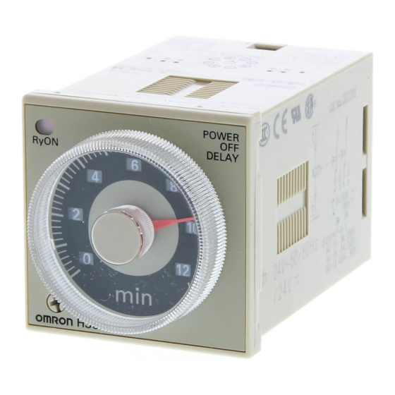
Page 16: H3Cr-A
100 to 240 VAC (50/60 Hz) H3CR-A8EL instantaneous contact 24 VDC/VAC (50/60 Hz) H3CR-A8E 48 to 125 VDC Note: Specify both the model number and supply voltage when ordering. Example: H3CR-A 12 VDC Supply voltage Accessories (Order Separately) Flush Mounting Adaptor Y92F-30 Socket 8-pin... - Page 17 Instantaneous output (To obtain instantaneous output, set to below 0.) (see note) 0.05 to 1.2 0.12 to 1.2 1.2 to 12 0.3 to 3 3 to 30 1.2 to 12 12 to 120 3 to 30 30 to 300 Note: Instantaneous output is available with all H3CR-A models.
- Page 18 Setting error Reset time Min. power-opening time: 0.1 s max. Min. pulse width: 0.05 s (H3CR-A/-AS) !0.5% FS max. (!0.5%!10 ms in a range of 1.2 s) Influence of voltage !2% FS max. (!2%!10 ms in a range of 1.2 s)
- Page 19 Operating mode display window Operating mode selector (select Output indicator (orange) a mode from A, B, B2, C, D, and E (H3CR-A and -AS), A and E (H3CR-A8, -A8S, -A8EL, -A8E) Scale range display windows Time unit display window Time range selector...
- Page 20 H3CR-A H3CR-A H3CR-A8/A8S Zero setting Time range/ Operating AC (DC) input detection unit selectors mode selector circuit Oscillation Power supply Counting Output circuit circuit circuit circuit Indicator circuit Power-ON Output-ON indicator indicator H3CR-A8EL/-A8E Zero setting Time range/ Operating AC (DC) input...
- Page 21 H3CR-A H3CR-A Basic Setting Setting of Selector Selection of Time Unit and Time Range The desired time unit (sec, min, hrs, or 10h) is displayed in the win- The selectors can be turned clockwise and counterclockwise to se- dow below the time setting knob by turning the time unit selector lo- lect the desired time unit, time range, or operating mode.
- Page 22 H3CR-A H3CR-A Timing Chart Note: 1. The minimum power-opening time (“Rt”) is 0.1 s and the minimum pulse width is 0.05 s. 2. The letter “t” in the timing charts stands for the set time and “t-a” means that the period is less than the time set.
- Page 23 H3CR-A H3CR-A Operating mode Timing chart t -- a t -- a t -- a Signal OFF-delay Power Start Reset Output relay (NC) Output relay (NO) (Output indicator) Power indicator Basic operation Power Start Output E: Interval t - a...
- Page 24 Power indicator Basic operation Power Start 1!0.6 s Output Note: The G and J modes are special modes. Order the H3CR-A-300 special model for these modes. Gate Signal Input Power Start Gate Reset Output relay Note: 1. This timing chart indicates the gate input in operating mode A (ON-delay operation).
- Page 25 H3CR-A H3CR-A H3CR-A8/-A8S Operating mode Timing chart A: ON-delay t - a Power Output relay (NC) Output relay (NO) (output indicator) Power indicator Basic operation Power Output E: Interval t - a Power Output relay (NC) Output relay (NO) (output...
- Page 26 H3CR-A H3CR-A Dimensions Note: All units are in millimeters unless otherwise indicated. H3CR-A 66.6 H3CR-AS 52.3 39 dia. 44.8 x 44.8 11 pins H3CR-A8 H3CR-A8S H3CR-A8E 66.6 52.3 44.8 x 44.8 39 dia. 8 pins H3CR-A8EL 63.7 44.8 x 44.8 39 dia.
- Page 27 H3CR-A H3CR-A Dimensions with Flush Mounting Adaptor Y92F-73/70 Panel Cutout Panel Adapter mounting hole Two, 4.5 dia. R0.5 max. 52 to 53 0.15 65 to 66 76!0.2 45!0.15 Note: The mounting panel thickness Dimensions with Flush Mounting Adaptor should be 1 to 3.2 mm.
- Page 28 H3CR-A H3CR-A Accessories (Order Separately) Track Mounting/ Front Connecting Socket P2CF-08 Terminal Arrangement/ Eight, Internal Connections M3.5 x 7.5 sems (Top View) Surface Mounting Holes Two, 4.5 dia. or two, M4 70 max. 35.4 Two, 4.5 dia. 40!0.2 holes 50 max.
- Page 29 H3CR-A H3CR-A End Plate Spacer PFP-M PFP-S 35.5 35.3 34.8 44.3 11.5 M4 x 8 pan head 16.5 screw Protective Cover Y92A-48B Y92A-48B The protective cover protects the front panel, particularly the time setting section, against dust, dirt, and water. It also prevents the set value from being altered due to accidental contact with the time set- ting knob.
- Page 30 H3CR-A H3CR-A Installation Terminal Arrangement H3CR-A (Contact Output) H3CR-AS (Transistor Output) (--)(~) Power supply (+)(~) (--)(~) Power supply (+)(~) H3CR-A8 (Contact Output) H3CR-A8S (Transistor Output) (--) (--) Power supply Power supply H3CR-A8EL/-A8E (Contact Output) (--) Power supply...
- Page 31 H3CR-A H3CR-A Input Connections The inputs of the H3CR are no-voltage (short circuit or open) inputs. No-voltage inputs No-contact Input Contact Input No-contact Input (Connection to NPN open (Connection to a voltage collector output sensor.) output sensor.) 12 to 24 VDC (sensor...
- Page 32 H3CR-A H3CR-A 3. Control of Integrated Time with Gate Signal 2. Signal Start/Signal Reset (in B Mode) With a gate signal, the Power-ON start operation and Signal start If there is an abnormal signal, flashing starts. When the abnormal operation can be controlled (the operation can be interrupted).
- Page 33 H3CR-A H3CR-A 2. Signal-ON-OFF Start/Instantaneous Operation/Time-limit 2. Signal Start/Instantaneous Operation/Time-limit Reset Reset t -- a Power (2 and 10) Power (2 and 10) Start (2 and 6) Start (2 and 6) Control output: NC (8 and 11) NC (1 and 4)
- Page 34 Power Supplies instantaneous contacts but time-limit contacts only. However, you can still design a self-holding circuit with the H3CR-A. For example, An AC power supply can be connected to the power input terminals circuit B is a self-holding circuit equivalent to circuit A, which in- without regarding polarity.
- Page 35 H3CR-A H3CR-A When connecting a relay or a transistor as an external signal input Environment device, pay attention to the following points to prevent short-circuit- When using the Timer in an area with excess electronic noise, sepa- ing due to a sneak current to the transformerless power supply.
-
Page 36: H3Cr-F/G/H
11-pin model 8-pin model H3CR-A8 H3CR-F-300 H3CR-H8RL 8-pin model H3CR-A8S H3CR-FN-300 H3CR-A8E H3CR-F8 8-pin with H3CR-A8EL H3CR-F8N instantaneous 8-pin model contact output H3CR-F8-300 model H3CR-F8N-300 Note: 1. H3CR-AS, H3CR-A8S: Transistor output models 2. Refer to the H3CR-A Datasheet (L84) for details. - Page 37 H3CR-F H3CR-F Solid-state Twin Timers H3CR-F DIN 48 x 48-mm Solid-state Twin Timers Wide power supply ranges of 100 to 240 VAC and 48 to 125 VDC respectively. Independent ON- and OFF-time settings. Further- more, combinations of long ON- or OFF-time and short OFF- or ON-time settings are possible.
- Page 38 H3CR-F H3CR-F Accessories (Order Separately) Name/specifications Models Flush Mounting Adapter Y92F-30 Y92F-73 Y92F-74 Mounting Track 50 cm (l) x 7.3 mm (t) PFP-50N 1 m (l) x 7.3 mm (t) PFP-100N 1 m (l) x 16 mm (t) PFP-100N2 End Plate PFP-M Spacer PFP-S...
- Page 39 H3CR-F H3CR-F Ratings Rated supply voltage (see note) 100 to 240 VAC (50/60 Hz),12 VDC, 24 VAC/DC (50/60 Hz), 48 to 125 VDC Operating voltage range 85% to 110% of rated supply voltage; 90% to 110% with 12-VDC models Power reset Minimum power-opening time: 0.1 s Power consumption 100 to 240 VAC: approx.
- Page 40 H3CR-F H3CR-F Nomenclature OFF indicator (green) OFF-time unit display window Lit when the output is OFF. OFF-time unit selector (select one from sec. ON indicator (orange) 10 s, min., and hrs, or from 10 s, 10 min, hrs, Lit when the output is ON. and 10 h) Scale range display ON-time setting knob (with orange pointer)
- Page 41 H3CR-F H3CR-F Timing Chart Operating mode Timing chart Flicker OFF start 0.1 s min. Power indicator Not lit indicator Not lit Output Output ON set time : OFF set time Flicker ON start 0.1 s min. Power indicator Not lit indicator Not lit Output...
- Page 42 H3CR-F H3CR-F Dimensions Note: All units are in millimeters unless otherwise indicated. H3CR-F 17.4 66.6 H3CR-FN 52.3 H3CR-F-300 H3CR-FN-300 44.8 x 44.8 37 dia 14 dia. R1.3 17.4 66.6 H3CR-F8 H3CR-F8N 52.3 H3CR-F8-300 H3CR-F8N-300 44.8 x 44.8 37 dia 14 dia. R1.3 Installation Terminal Arrangement...
- Page 43 H3CR-G H3CR-G Solid-state Star-delta Timer H3CR-G DIN 48 x 48-mm Solid-state Star-delta Timer A wide star-time range (up to 120 seconds) and star-delta transfer time range (up to 0.5 seconds). Ordering Information Outputs Supply voltage 8-pin models Time-limit contact 100 to 120 VAC H3CR-G8L 200 to 240 VAC Time-limit contact and instantaneous contact...
- Page 44 H3CR-G H3CR-G Accessories (Order Separately) Name/specifications Models Flush Mounting Adapter Y92F-30 Y92F-70 Y92F-71 Mounting Track 50 cm (l) x 7.3 mm (t) PFP-50N 1 m (l) x 7.3 mm (t) PFP-100N 1 m (l) x 16 mm (t) PFP-100N2 End Plate PFP-M Spacer PFP-S...
- Page 45 H3CR-G H3CR-G Time Ranges Star-delta transfer 0.05 sec 0.1 sec 0.25 sec 0.5 sec time Star 0.5 to 6 sec operation 1 to 12 sec time setting time setting 5 to 60 sec 10 to 120 sec Ratings Rated supply voltage 100 to 120 VAC (50/60 Hz), 200 to 240 VAC (50/60 Hz) Operating voltage range 85% to 110% of rated supply voltage...
- Page 46 H3CR-G H3CR-G Engineering Data 10,000 5,000 1,000 Reference: A maximum current of 0.15 A can be switched at 125 VDC (cosf = 1) 30 VDC L/R = 7 ms and a maximum current of 0.1 A can be switched if L/R is 7 ms. In both cases, a life of 100,000 operations can be expected.
- Page 47 H3CR-G H3CR-G Operation Block Diagrams H3CR-G8L Star Star-delta operation transfer time time range selector selector Star-delta Star-delta Star operation Star Power transfer time transfer time time operation AC input Star operation supply oscillation counting oscillation time counting Output circuit circuit circuit circuit circuit...
- Page 48 H3CR-G H3CR-G Using the Setting Ring Setting a Specific Time Mount the Panel Cover on the Timer, set the desired time with the time setting knob, and place Time Setting Ring A onto the time setting knob so that the time setting notch of Time Setting Ring A is in the center of the reset lock position of the Panel Cover. Setting position Time setting notch Reset lock position...
- Page 49 H3CR-G H3CR-G Dimensions Note: All units are in millimeters unless otherwise indicated. 78.0 63.7 44.8 x 44.8 39 dia Dimensions with Set Ring 16.5 42 dia. Time setting ring Panel cover Time Setting Ring/Panel Cover There are three types of Panel Covers (Y92P-48GL, Y92P-48GB, Setting a specific Time Setting Ring A (Y92S-27) and and Y92P-48GM), all of which are available in three colors.
- Page 50 H3CR-G H3CR-G Installation Terminal Arrangement H3CR-G8L H3CR-G8EL Delta Star Delta Star operation operation operation operation Instantaneous contact contact contact contact contact ( ~ ) ( ~ ) ( ~ ) ( ~ ) Note: Leave terminals 1, 3, and 4 open. Note: Leave terminal 4 open.
- Page 51 H3CR-H H3CR-H Solid-state Power OFF-delay Timer H3CR-H DIN 48 x 48-mm Solid-state Power OFF-delay Timer Long power OFF-delay times; S-series: up to 12 seconds, M-series: up to 12 minutes. Models with forced-reset input are available. 11-pin and 8-pin models are available. Ordering Information Input Output...
- Page 52 H3CR-H H3CR-H Accessories (Order Separately) Name/specifications Models Flush Mounting Adapter Y92F-30 Y92F-70 Y92F-71 Mounting Track 50 cm (l) x 7.3 mm (t) PFP-50N 1 m (l) x 7.3 mm (t) PFP-100N 1 m (l) x 16 mm (t) PFP-100N2 End Plate PFP-M Spacer PFP-S...
- Page 53 H3CR-H H3CR-H Ratings Rated supply voltage (see note) 100 to 120 VAC (50/60 Hz), 200 to 240 VAC (50/60 Hz), 24 VAC/VDC (50/60 Hz), 48 VDC, 100 to 125 VDC Operating voltage range 85% to 110% of rated supply voltage No-voltage input ON-impedance: 1 k$ max.
- Page 54 H3CR-H H3CR-H Engineering Data 10,000 5,000 1,000 Reference: A maximum current of 0.15 A can be switched at 125 VDC (cos% = 1) 30 VDC L/R = 7 ms and a maximum current of 0.1 A can be switched if L/R is 7 ms. In both cases, a life of 100,000 operations can be expected.
- Page 55 H3CR-H H3CR-H With Reset Input (H3CR-H8RL/-HRL) Time range selector Power supply Oscillation Counting Output AC (DC) input circuit circuit circuit circuit Power failure Indicator Output detection circuit circuit indicator Reset input Input circuit I/O Functions Inputs Reset Turns off the control output and resets the elapsed time. Outputs Control output Operates instantaneously when the power is turned on and time-limit resets when the set time...
- Page 56 H3CR-H H3CR-H Timing Chart Model Timing chart H3CR-H8L Power Output (1 -- 3) Output (1 -- 4) Output (8 -- 6) Output (8 -- 5) Output indicator Not lit H3CR-H8RL Power 0.05 s min. 0.05 s min. ON (Short-circuited) Reset input OFF (Open) Output (8 -- 6) Output (8 -- 5)
- Page 57 H3CR-H H3CR-H H3CR-H8L 78.0 H3CR-H8RL 63.7 39 dia 44.8 x 44.8 78.0 H3CR-HRL 63.7 39 dia 44.8 x 44.8 Installation Terminal Arrangement 8-pin Models Without Reset Input (H3CR-H8L) With Reset Input (H3CR-H8RL) Reset input (--) (--) Power supply Power supply Note: Leave terminal 3 open.
- Page 58 A star operation time range (0 to 6, 0 to 12, 0 to 60, or 0 to 120 se- (i.e., H3CR-A) conds) is selected with the star operation time range selector at the lower left corner of the front panel.
- Page 59 H3CR-F/G/H H3CR-F/G/H H3CR-H Power OFF-delay Timers A time range (0 to 0.6, 0 to 1.2, 0 to 6, and 0 to 12) is selected with the time range selector at the lower left corner of the front panel. No time unit selector is available.
- Page 60 H3CR-F/G/H H3CR-F/G/H Dimensions with Flush Mounting Adaptor Y92F-73/-70 Panel Cutout Panel Adapter mounting hole Two, 4.5 dia. R0.5 max. 52 to 53 45!0 65 to 66 76!0.2 45!0.15 Note: The mounting panel thickness Dimensions with Flush Mounting Adaptor should be 1 to 3.2 mm. Y92F-74/-71 Panel R0.5 max.
- Page 61 H3CR-F/G/H H3CR-F/G/H Accessories (Order Separately) Track Mounting/ Front Connecting Socket P2CF-08 Terminal Arrangement/ Eight, Internal Connections M3.5 x 7.5 sems (Top View) Surface Mounting Holes Two, 4.5 dia. or two, M4 70 max. 35.4 Two, 4.5 dia. 40!0.2 holes 50 max. 20.3 max.
- Page 62 H3CR-F/G/H H3CR-F/G/H End Plate Spacer PFP-M PFP-S 35.5 35.3 34.8 44.3 11.5 M4 x 8 pan head 16.5 screw Protective Cover Y92A-48B Y92A-48B The protective cover protects the front panel, particularly the time setting section, against dust, dirt, and water. It also prevents the set value from being altered due to accidental contact with the time set- ting knob.
- Page 63 ON the output. If it is required that the output be turned on repeatedly with an inter- val of shorter than 3 s, consider use of the H3CR-A in mode D (sig- nal OFF-delay). Inrush Current...
- Page 64 H3CR-F/G/H H3CR-F/G/H Input/Output (H3CR-H) Others An appropriate input is applied to the input signal terminal of the Tim- If the Timer is mounted on a control board, dismount the timer from er when the input terminal for the input signal is short-circuited. Do the control board or short-circuit the circuitry of the power board be- not attempt to connect any input terminal to any terminal other than fore carrying out a voltage withstand test between the electric cir-...
-
Page 65: H3Dr-A/P/M
Solid-state Timer H3DR-A/P/M DIN-track Mounted, Standard 22.5-mm Width Timer Range Conforms to VDE0435/0110 and approved by UL and CSA. Conforms to EMC standards. NPN and PNP Input Models are available. Name plates provided for easy timer identification and management. Finger-protection terminal block. Delivered with an open terminal for quick installation. - Page 66 H3DR-A/P/M H3DR-A/P/M Model Legend of H3DR Series H3DR Full-multifunction Multifunction Single-function DPDT Output Transistor NPN Input PNP Input Output -ASP NPN Input PNP Input NPN Input PNP Input Ordering Information NPN (No-voltage) Input Models Supply voltage Outputs Time range Operating mode Model 100 to 240 VAC (50/60 Hz) Contact (DPDT)
- Page 67 H3DR-A/P/M H3DR-A/P/M Accessories (Order Separately) Mounting Track 50 cm (l) x 7.3 mm (t) PFP-50N 1 m (l) x 7.3 mm (t) PFP-100N 1 m (l) x 16 mm (t) PFP-100N2 End Plate PFP-M Spacer PFP-S Specifications General Item H3DR-A/-AS H3DR-AP/-ASP H3DR-P H3DR-PP...
- Page 68 H3DR-A/P/M H3DR-A/P/M Ratings NPN (No-voltage) Input Models Item H3DR-A H3DR-AS H3DR-P Rated supply 100 to 240 VAC (50/60 Hz), 12 VDC, 100 to 120 VAC (50/60 Hz), voltage 12 VDC, 24 VDC/VAC (50/60 Hz) 200 to 240 VAC (50/60 Hz), 24 VDC/VAC (50/60 Hz) 24 VDC/VAC (50/60 Hz) Operating...
- Page 69 H3DR-A/P/M H3DR-A/P/M No-input Models Item H3DR-M Rated supply 110 to 120 VAC (50/60 Hz), voltage 220 to 240 VAC (50/60 Hz), 24 VDC/VAC (50/60 Hz) Operating 85% to 110% of rated supply voltage voltage range Power reset Minimum power-opening time: 0.1 s Power 110 to 120 VAC: approx.
- Page 70 H3DR-A/P/M H3DR-A/P/M PNP (Voltage) Input Models Item H3DR-AP/-ASP/-PP !1% FS max. (!1%!10 ms in a range of 1.2 s) Accuracy of operating time !10% FS !0.05 s max. Setting error Reset time Min. power-opening time: 0.1 s; Min. pulse width: 0.05 s Reset voltage 10% max.
- Page 71 H3DR-A/P/M H3DR-A/P/M No-input Models Item H3DR-M !2% FS max. Accuracy of operating time !10% FS !0.05 s max. Setting error Reset time Min. power-opening time: 0.1 s Reset voltage 10% max. of rated supply voltage (10 V max. for 100 to 240 VAC, 100 to 120 VAC; 20 V max.
- Page 72 H3DR-A/P/M H3DR-A/P/M Nomenclature NPN Input Models H3DR-A/-AS Scale range Time unit display display window window Scale range selector (select 0.1 or 1) Power indicator (green) (Flashes when Name plate for user use (20 x 6.6 mm) Timer operates; lit when Timer stops Time unit selector (select one operating) from sec, min, hrs, and 10 h)
- Page 73 H3DR-A/P/M H3DR-A/P/M PNP Input Models H3DR-AP/-ASP Scale range Time unit display display window window Scale range selector (select 0.1 or 1) Power indicator (green) (Flashes when Name plate for user use (20 x 8 mm) Timer operates; lit when Timer stops Time unit selector (select one operating) from sec, min, hrs, and 10 h)
- Page 74 H3DR-A/P/M H3DR-A/P/M Operation Block Diagram H3DR-A/-AS/-AP/-ASP Zero setting Time range/ Operating AC (DC) input detection unit selectors mode selector circuit Oscillation Power supply Counting Output circuit circuit circuit circuit Indicator Input circuit Reset input, start input, and gate input circuit Power-ON Output-ON indicator...
- Page 75 H3DR-A/P/M H3DR-A/P/M I/O Functions H3DR-A/-AS/-AP/-ASP Inputs Start Starts time-measurement. Reset Interrupts time-measurement and resets preset time-measurement value. No time-measurement is made and control output is OFF while the reset input is ON. Gate Prohibits time-measurement. Output Control output Outputs are turned ON according to designated output mode when preset value is reached. H3DR-P/-PP Input Start...
- Page 76 H3DR-A/P/M H3DR-A/P/M Timing Chart Note: 1. The minimum power-opening time is 0.1 s and the minimum pulse width is 0.05 s. 2. The letter t in the timing charts stands for the set time and t-a means that the period is less than the time set. NPN/PNP Input Models H3DR-A/-AS/-AP/-ASP Operating mode...
- Page 77 H3DR-A/P/M H3DR-A/P/M Operating mode Timing chart t -- a t -- a t -- a Signal OFF-delay Power Start (see note) Reset (see note) Output relay (NC) Output relay (NO) (Output indicator) Power indicator Basic operation Power Start Output E: Interval For power-on operation, short-circuit the start input and input common terminal.
- Page 78 H3DR-A/P/M H3DR-A/P/M Operating mode Timing chart t - a t - a Basic operation Signal ON/OFF-delay Power Power Start (see note) Reset Start (see note) Output relay (NC) Output Output relay (NO) (Output indicator) Power indicator For power-on operation, short-circuit the start input and input common terminal. One-shot output The timer starts operating at the moment the power is turned on.
- Page 79 H3DR-A/P/M H3DR-A/P/M H3DR-P/-PP Operating Timing chart mode A: ON-delay For power-on operation, short-circuit the start input and input common terminal. The timer starts operating at the moment the power is turned on. t--a Power (A and A Basic operation Start (see note) Power Output relay (NC, 15 and 16)
- Page 80 H3DR-A/P/M H3DR-A/P/M Operating Timing chart mode t--a t--a Signal ON/OFF- delay Power (A and A Start (see note) Basic operation Power Output relay (NC, 15 and 16) Start Output relay (NO, 15 to 18) (output indicator) Output Power indicator t--a t--a t--a Signal...
- Page 81 H3DR-A/P/M H3DR-A/P/M Dimensions Note: All units are in millimeters unless otherwise indicated. H3DR-A/-AS/-AP/-ASP H3DR-P/-PP H3DR-M Wiring terminal (M3 fork or single wire is connectable) 22.5 23.5 76.5 (100) Accessories (Order Separately) Mounting Track PFP-100N, PFP-50N PFP-100N2 7.3!0.15 29.2 35!0.3 27!0.15 35!0.3 25 15 L: Length...
- Page 82 H3DR-A/P/M H3DR-A/P/M Installation Terminal Arrangement NPN Input Models H3DR-A H3DR-AS DPDT Relay Output Transistor Output Reset Start Gate Reset Start Gate Power Power supply supply H3DR-P Note: The H3DR-A/-P incorporates multiple operating modes (6 modes), thus uses a new timer contact symbols which are different from conventional ones used for other digital timers.
- Page 83 H3DR-A/P/M H3DR-A/P/M PNP Input Models H3DR-AP H3DR-ASP DPDT Relay Output Transistor Output Power Power supply supply Reset Start Gate Reset Start Gate H3DR-PP Note: The H3DR-AP/-PP incorporates multiple operating modes (6 modes), thus uses a new timer contact symbols which are different from conventional ones used for other digital timers.
- Page 84 H3DR-A/P/M H3DR-A/P/M Input Connections (H3DR-A/-P/-AP/-PP) NPN Input Models The inputs of the H3DR-A/-AS/-P are no-voltage (short circuit or open) inputs. H3DR-A/-AS No-voltage inputs No-contact Input No-contact Input Contact Input (Connection to a voltage (Connection to NPN open output sensor.) collector output sensor.) 12 to 24 VDC (sensor 12 to 24 VDC (sensor power supply)
- Page 85 H3DR-A/P/M H3DR-A/P/M PNP Input Models The inputs of the H3DR-AP/--ASP/-PP are voltage (voltage imposition or open) inputs. H3DR-AP/-ASP Voltage Inputs No-contact Input Contact Input (Connection to PNP output sensor.) 12 to 24 VDC (sensor power supply) DC power supply Voltage Input Signal Levels 1.
- Page 86 H3DR-A/P/M H3DR-A/P/M Precautions Changing of Setting Power Supplies An AC power supply can be connected to the power input terminals NOTICE: Do not change the time unit, rated time, or operating without regarding polarity. A DC power supply must be connected to mode while the timer is in operation or malfunction could the power input terminals as designated according to the polarity of result.
- Page 87 H3DR-A/P/M H3DR-A/P/M Input/Output NPN Input Models PNP Input Models H3DR-A/-AS H3DR-AP/-ASP Input terminal Input terminal G, S, R S, R, G H3DR-AP/ H3DR-A/-AS Power supply H3DR-ASP AC or DC Power supply Input contact AC or DC Do not connect a relay or any other load between these two points, An appropriate input is applied to the input signal terminals of the otherwise the internal circuit of the Timer may be damaged due to Timer when one of the input terminals (terminals B...
- Page 88 H3DR-A/P/M H3DR-A/P/M Output Connection of H3DR-AS with Environment Transistor Output When using the Timer in an area with excess electronic noise, sepa- rate the Timer, wiring, and the equipment which generates the input The H3DR-AS transistor output is insulated from the internal circuit- signals as far as possible from the noise sources.
-
Page 89: H3Dr-F/G/H
Solid-state Timer H3DR-F/G/H A Wide Variety of DIN 22.5-mm Width Timer Ranges: H3DR-F Twin Timer, H3DR-G Star-delta Timer, and H3DR-H Power OFF-delay Timer Conforms to VDE0435, 0110 and approved by UL and CSA. Conforms to EMC standards. Name plates provided for easy timer identification and management. Finger-protection terminal block (conforms to VDE0106) compatible with bar-sleeve or fork connectors. - Page 90 H3DR-F H3DR-F Solid-state Twin Timer H3DR-F DIN 22.5-mm Solid-state Twin Timers High immunity to invertor noise. Independent ON- and OFF-time settings. Com- binations of long ON- or OFF-time and short OFF- or ON-time settings are possible. Seven time ranges from 0.1 s to 12 h. Wide AC power supply range: 100 to 240 VAC.
- Page 91 H3DR-F H3DR-F Time Ranges Time unit 10 s Instantaneous (see note) Setting Time scale: x 0.1 s 0.1 to 1.2 s 1 to 12 s 0.1 to 1.2 min 0.1 to 1.2 h Time scale: x 1 s 1 to 12 s 10 to 120 s 1 to 12 min 1 to 12 h...
- Page 92 H3DR-F H3DR-F Engineering Data 10,000 5,000 1,000 30 VDC, L/R = 7 ms 250 VAC/30 VDC (cos% = 1) Reference: A maximum current of 0.15 A can be switched at 125 VDC (cos% = 1) 250 VAC (cos% = 0.4) and a maximum current of 0.1 A can be switched if L/R is 7 ms.
- Page 93 H3DR-F H3DR-F Operation Basic Operation Time Unit Selection Time Scale Selection For ON-time, the desired time unit (s, 10 s, min, and h) is indicated The scale (0.1 or 1) is selected with the time scale selector at the on the ON-time unit display window at the upper-right corner of the upper-left corner of the front panel and appears in the window above front panel and can be changed by turning the ON-time unit selector the selector.
- Page 94 H3DR-F H3DR-F Timing Chart 0.1 s min. Power indicator indicator Output Note: t : ON set time OFF set time OFF: Allow at least 0.1 s for recovery. Dimensions Note: All units are in millimeters unless otherwise indicated. Installation Terminal Arrangement Power supply...
- Page 95 H3DR-G H3DR-G Solid-state Star-delta Timer H3DR-G DIN 22.5-mm Solid-state Star-delta Timer High immunity to invertor noise. A wide star-time range (up to 120 seconds) and star-delta transfer time range (up to 0.5 seconds). Ordering Information Supply voltage Model 100 to 240 VAC H3DR-G 48 VAC 24 VAC/DC...
- Page 96 H3DR-G H3DR-G Time Ranges Star-delta transfer time 0.05 sec 0.1 sec 0.25 sec 0.5 sec Star operation time Time scale: x 1 s 1 to 12 s setting Time scale: x 10 s 10 to 120 s Ratings Rated supply voltage (see note) 100 to 240 VAC (50/60 Hz), 48 VAC (50/60 Hz), 24 VAC/DC (50/60 Hz) Operating voltage range 85% to 110% of rated supply voltage...
- Page 97 H3DR-G H3DR-G Engineering Data 10,000 5,000 1,000 30 VDC, L/R = 7 ms 250 VAC/30 VDC (cos% = 1) 250 VAC (cos% = 0.4) Reference: A maximum current of 0.15 A can be switched at 125 VDC (cos% = 1) and a maximum current of 0.1 A can be switched if L/R is 7 ms.
- Page 98 H3DR-G H3DR-G Operation Basic Operation Time Unit Selection Time Scale Selection The time required for switching (0.05, 0.1, 0.25, or 0.5 s) from the The scale (1 or 10) is selected with the time scale selector at the up- star operation to the delta operation can be selected with the star- per-left corner of the front panel and appears in the window above delta transfer time selector at the lower-right corner of the front pan- the selector.
- Page 99 H3DR-G H3DR-G Timing Chart 0.5 s min. Power Star operation contact Delta operation contact Star operation indicator Delta operation indicator Note: t : Star operation time setting : Star-delta transfer time Dimensions Note: All units are in millimeters unless otherwise indicated. Installation Terminal Arrangement Power...
- Page 100 H3DR-H H3DR-H Solid-state Power OFF-delay Timer H3DR-H DIN 22.5-mm Solid-state Power OFF-delay Timer High immunity to invertor noise. Long power OFF-delay times; S-series: up to 12 seconds, L-series: up to 120 seconds. Ordering Information Supply voltage S-series L-series 100 to 120 VAC H3DR-H H3DR-H 200 to 240 VAC...
- Page 101 H3DR-H H3DR-H Time Ranges Time ranges Setting Setting range Min. power ON time S-series Time scale: x 0.1 0.1 to 1.2 s 0.1 s min. Time scale: x 1 1 to 12 s L-series Time scale: x 1 1 to 12 s 0.3 s min.
- Page 102 H3DR-H H3DR-H Engineering Data 10,000 5,000 1,000 30 VDC, L/R = 7 ms 250 VAC/30 VDC (cos% = 1) 250 VAC (cos% = 0.4) Reference: The minimum applicable load is 100 mA at 5 VDC (failure level: P). Load current (A) Nomenclature Nameplate (for user application) (20 x 6.6 white panel)
- Page 103 H3DR-H H3DR-H Operation Basic Operation Time Scale Selection Time Setting The scale is selected with the time scale selector at the upper-left Use the main dial to set the operation time. corner of the front panel and appears in the window above the selec- The fine-tuning dial is useful when delicate or more accurate adjust- tor: 0.1 or 1 for S-series, 1 x 10 for L-series ment is required.
- Page 104 H3DR-H H3DR-H Timing Chart Power Output indicator Note: t: Set time Rt: Minimum power On time (S-series: 0.1 s min.; L-series: 0.3 s min.) (The output may never turn ON if a value equal to or less than this value is used.) Dimensions Note: All units are in millimeters unless otherwise indicated.
- Page 105 H3DR-H H3DR-H Installation Terminal Arrangement Power supply...
- Page 106 H3DR-F/G/H H3DR-F/G/H Dimensions Note: The undermentioned is common for all H3DR-F/G/H models. Note: All units are in millimeters unless otherwise indicated. Accessories (Order Separately) Mounting Track PFP-100N, PFP-50N L: Length 7.3!0.15 PFP-100N 50 cm PFP-50N 35!0.3 27!0.15 End Plate Spacer PFP-M PFP-S 35.5 35.3...
- Page 107 H3DR-F/G/H H3DR-F/G/H Precautions Note: The undermentioned is common for all H3DR-F/G/H models. Changing of Setting Caution Do not change the time unit, time range, or operation mode while the timer is in operation or malfunction could result. Power Supplies An AC power supply can be connected to the power input terminals without regarding polarity.
- Page 108 H3DR-F/G/H H3DR-F/G/H Mounting and Dismounting Others The H3DR should be mounted as horizontally as possible. If the Timer is mounted on a control board, dismount the timer from the control board or short-circuit the circuitry of the power board be- When mounting the H3DR on a socket mounting track, hook portion fore carrying out a voltage withstand test between the electric cir- (A) of the Timer to an edge of the track first, and then depress the...
-
Page 109: H3Ca
Solid-state Timer H3CA DIN-sized (48 x 48, 45 x 75 mm) Timer with Digital Setting and LCD Display Dual power supplies for free AC/DC. Eight operation modes selectable with one unit. Any desired time can be set digitally within a range from 0.1 seconds to 9,990 hrs. - Page 110 H3CA H3CA Ratings Item H3CA-A/H3CA-FA H3CA-8 H3CA-8H Rated supply voltage 24 to 240 VAC (50/60 Hz), 100/110/120, 200/220/240 VAC, (50/60 Hz), 12 to 240 VDC (permissible 24 VDC (permissible ripple: 20% max.) (see note) ripple: 20% max.) Operating voltage range 90% to 110% of rated supply 85% to 110% of rated supply voltage voltage...
- Page 111 H3CA H3CA Nomenclature H3CA-A/H3CA-8H H3CA-FA Time Unit Selector LCD Display LCD Display Control output ON/OFF indication Remaining time elapses, the re- maining time is indicated by a pattern of bars in tenth of 1/10 of the set time. Time Unit Selector Set Time Indicators (3 Digits) Operation Mode Selector (Fixed to “A”...
- Page 112 H3CA H3CA Signal ON/OFF-delay Operation 1 (C Mode) Signal OFF-delay Operation 1 (D Mode) t: Set time; t-a: Time within the set time t: Set time; t-a: Time within the set time Note: 1. The minimum signal input time is 0.05 s. 2.
- Page 113 H3CA H3CA How to Use Gate Signal Input How to Use Check Signal Input If a check signal is input to the timer during the lapse of a set time, the remaining set time will become 0 and the timer will enter the next control state.
- Page 114 H3CA H3CA Dimensions Note: All units are in millimeters unless otherwise indicated. Timers H3CA-A/-8H H3CA-FA Panel Cutouts Mounting Holes Two,M4 or 4.5 dia. holes Horizontally connecting n units When mounting a No front cover: single unit N = (48n -- 2.5) t = 1 to 3.2 mm Note: When mounting two or With front cover:...
- Page 115 H3CA H3CA Back Connecting Socket P3GA-11 Terminal Arrangement (Bottom View) 27 dia. P3G-08 Terminal Arrangement Mounting Height of (Bottom View) Timer with Socket 10.9 86.3 M3.5 P3G-08 PL11 Terminal Arrangement Mounting Holes Mounting Height of (Bottom View) Timer with Socket Two, 3.5 dia.
- Page 116 H3CA H3CA Mounting Track (Meets DIN EN50022) PFP-100N/PFP-50N PFP-100N2 Twelve, 25 ' 4.5 elliptic holes (see note) (see note) Note: This dimension applied to PFP-50N. Note: A total of 12-25 x 4.5 elliptic holes are provided with 6 holes cut from each rail end at a pitch of 10 mm between holes. End Plate PFP-S PFP-M...
- Page 117 H3CA H3CA Installation Terminal Arrangement H3CA-A H3CA-FA * * * * (+) or (--) * * * * (See note (See note (+) or (+) or (--) (--) Note: 1. *C: Check: C--D *G: Gate: C--E Note: 1. *C: Check: X-E1 *S: Start: C--F *G: Gate: X-D1 *R: Reset: C--G...
- Page 118 H3CA H3CA From a solid-state circuit (proximity sensor, photoelectric sensor, or the like) with rated power supply voltage ranging from 6 to 30 VDC, input signals can also be applied by other than an open collector type transistor as shown in the following diagram. The input signal from a solid-state circuit is applied when output transistor Tr turns ON.
- Page 119 H3CA H3CA Application Examples Standard type H3CA is used for the following application examples. In the schematic diagrams, each thick the indicates the wiring necessary for selecting the desired operation mode. ON-delay Operation (A Mode) Power-ON Start/Power-OFF Reset Signal Start/Signal Reset (+) or (--) or (--) (+) or (--)
- Page 120 H3CA H3CA Signal ON/OFF-delay Operation 2 (G Mode) Signal ON/OFF-start/Instantaneous Operation/ Signal Start/Signal Reset Time-limit Reset (+) or (--) (+) or (--) or (--) (+) or (--) Interval Operation (E Mode) Power-ON Start/Power-OFF Reset Signal Start/Signal Reset (+) or (--) or (--) (+) or (--) or (--)
- Page 121 H3CA H3CA Precautions How to Change Operation Mode Connecting the Operating Power Supply Operate the pushbuttons of the thumbwheel switch, located at the The H3CA-8j contains a capacitor-drop power circuit. Use a sinu- leftmost position on the front panel to set the operation mode. Eight soidal power supply with a commercial frequency.
- Page 122 H3CA H3CA Others Holding relays are used for outputs on the H3CA-A Series. Drop- ping the Unit or otherwise subjecting it to shock can cause the relay to reverse or to move to the center position. How to Mount the Timer on Mounting Track When mounting a H3CA-FA Timer on a socket mounting track, ob- serve the following procedures: Mounting...
-
Page 123: New H3Y
Solid-state Timer New H3Y Miniature Timer Compatible with the MY Relay Semi-multi power supply voltage. Large transparent time setting knob facilitates time setting. A flat-blade and Phillips screwdriver can also be used for time setting. Pin configuration compatible with MY Power Relay. LED indication for power and output statuses. - Page 124 3. The model designed for a power consumption of 200 to 230 VAC at 50/60 Hz can be used within the permissible voltage fluctuation range of 170 to 230 VAC. Please contact your OMRON representative if models with specifications of 240 VAC, 50/60 Hz (85% to...
- Page 125 New H3Y New H3Y Characteristics !1% FS max. (0.5 s range: !1%!10 ms max.) Accuracy of operating time !10%!50 ms FS max. Setting error (see note 1) Reset time Min. power-opening time: 0.1 s max. (including halfway reset) Reset voltage 10% max.
- Page 126 New H3Y New H3Y Engineering Data H3Y-2, H3Y-2-0 H3Y-2, H3Y-2-0 250 VAC, cos% = 1 250 VAC, cos% = 0.4 24 VDC, cos% = 1 24 VDC, L/R = 7 ms Load current (A) Load current (A) Reference: A maximum current of 0.6 A can be switched at 125 VDC (cos% = 1). Maximum current of 0.2 A can be switched if L/R is 7 ms.
- Page 127 New H3Y New H3Y Dimensions Note: All units are in millimeters unless otherwise indicated. Timers H3Y-2 H3Y-4 28 max. 28 max. 21.5 21.5 max. max. (63.0) (63.0) H3Y-2-0 H3Y-4-0, H3Y-4-CB-0 28 max. 28 max. 21.5 21.5 max. (60.7) max. (60.7) Mounting Holes Mounting Holes Eight,...
- Page 128 New H3Y New H3Y Accessories (Order Separately) Use the PYFjA, PYj, PYj-02, or PYjQN(2) to mount the H3Y. When ordering any one of these sockets, replace “j” with “08” or “14.” Track Mounting/Front Connecting Sockets PYF08A Two, 4.2 ' 5 Terminal Arrangement Mounting Holes mounting holes...
- Page 129 New H3Y New H3Y Back Connecting Sockets PY08, PY14 Terminal Arrangement Panel Cutout Eight, 3 ' 1.2 dia. holes (Bottom View) only for PY08 (Fourteen, 3 ' 1.2 dia. holes) +0.2 21.4 24 max. Series 29.5 59.3 25.5 max. +0.2 max.
- Page 130 New H3Y New H3Y Socket Mounting Plates (t = 1.6) Applicable socket For mounting 1 socket For mounting 18 sockets PY08, PY14, PY08QN(2), PY14QN(2) PYP-1 PYP-18 Note: PYP-18 may be cut to any desired length. PYP-1 PYP-18 Two, 3.4-dia. holes Relay Hold-down Clips Y92H-3 for Y92H-4 for...
- Page 131 New H3Y New H3Y Installation Connection H3Y-2, H3Y-2-0 H3Y-4, H3Y-4-0 Connect the DC power supply to Connect the DC power supply to terminals 13 and 14 according terminals 13 and 14 according to to the polarity marks. the polarity marks. Precautions When selecting a control output, use the H3Y-2 for switching ON Do not use the H3Y in places where there is excessive dust, corro-...
-
Page 132: H3M
Solid-state Timer Solid-state Timer with Variable Time Ranges Four time ranges are selectable per timer unit. Wide timing range of 0.05 second to 30 hours can be covered by a combination of five timer units. Standard surface mounting type is easily convert- ible to flush mounting type with the use of a special adapter (Y92F-40). - Page 133 Ratings Rated supply voltage 100/110/120 VAC (50/60 Hz), 200/220/240 VAC (50/60 Hz), 12, 24, 48, 100, 110 VDC (see note 2) Operating voltage range AC: 85% to 110% of rated supply voltage DC: 80% to 110% of rated supply voltage (see note 3) Power consumption AC: Approx.
- Page 134 Operation Timing Chart H3M-H Dimensions Note: All units are in millimeters unless otherwise indicated. H3M(-H) Accessories (Order Separately) Y92F-40 Adapter with Flush Mounting Note: When two or more timers mounted in line are to be continuously energized at the same time after the lapse of the set time, be sure to limit the carry current to less than 1 A.
- Page 135 Terminal Arrangement Mounting Holes Mounting Height of (Top View) Timer with Socket Two, M4 Back Connecting Socket PL08 Terminal Arrangement Mounting Holes Mounting Height of (Bottom View) Timer with Socket Two, 2 dia. Two, 3.5 dia. or M3 holes socket mounting holes P3G-08 Terminal Arrangement...
- Page 136 Installation Connection H3M-H Precautions Power Source Connection Caution Because the AC-operated version is a capacitive load, the solid- Be sure to turn the power off before changing the time specifi- state relay to be used must be rated at a dielectric strength two times cation.
-
Page 137: H3Fa
Solid-state Timer H3FA DIP Model Timer for PC Board Use Provides Contact and Solid-state Output Four rated times available: models suffixed -A and -SA: 1 s, 10 s, 1 min, 10 min; models suffixed -B and -SB: 6 s, 60 s, 6 min, 60 min. Timer operation may also be controlled through an external variable resistor. - Page 138 H3FA H3FA Ratings Item H3FA-A(U)/H3FA-B(U) H3FA-SA(U)/H3FA-SB(U) Rated supply voltage 5, 6, 12, or 24 VDC (see note 1) 5/6 VDC, 12/24 VDC (see notes 1 and 2) Operating voltage range 5 VDC: 90% to 110% of rated supply voltage 5/6 VDC: 90% to 110% of rated supply voltage 6, 12, 24 VDC: 85% to 110% of rated supply voltage 12/24 VDC: 85% to 110% of rated supply voltage Power consumption...
- Page 139 H3FA H3FA Operation Timing Chart H3FA-A/H3FA-B/H3FA-SA/H3FA-SB Standard Operation (ON-delay Operation) Integration Operation (See note) (See note) Note: When using the 12/24 VDC operated timer with a 12 VDC power supply, short-circuit terminals 13 and 15. Note: 1. Control output is provided when the set time or T ) is up.
- Page 140 H3FA H3FA External Resistor and Operate Time When using an external resistor, refer to the characteristic diagrams shown below. Use an external resistor rated at about 0.1 W/1 M$ for H3FA(U) and -SA(U), and 0.1W/3 M$ for H3FA-B(U) and -SB(U). Pay attention to external noise and keep the lead length to less than 2 m.
- Page 141 H3FA H3FA Dimensions Note: All units are in millimeters unless otherwise indicated. H3FA-A, H3FA-B, H3FA-SA, H3FA-SB Mounting Holes (Top View) H3FA-A/-B Twelve, 1.0 dia. holes H3FA-SA/-SB Twelve, 1.0 dia. holes Applicable Connecting Socket Standard 24-pin IC socket can be used for mounting the time unit. H3FA-AU, H3FA-BU, H3FA-SAU, H3FA-SBU Mounting Holes (Top View) H3FA-AU/-BU...
- Page 142 H3FA H3FA Installation Connection Note: Do not apply voltage to any terminal other than the power supply terminals. Otherwise, the internal circuitry may be damaged. H3FA-A, H3FA-B, H3FA-SA, H3FA-SB Standard Operation (ON-delay Operation) Integration Operation When the set time has elapsed subsequent to the power application By opening the terminals connected to the internal variable resistor (connect power to terminals A and X, and short-circuit terminals M (U and V), or external resistor (U and W), timer operation can be in-...
- Page 143 H3FA H3FA OFF-delay Operation by External Signal H3FA-AU, H3FA-BU, H3FA-SAU, H3FA-SBU The time unit can be reset through the application of an external re- One-shot Output Operation set signal. This permits the time unit to perform OFF-delay opera- Upon power application (connect power to terminals A and X short- tion.
- Page 144 H3FA H3FA OFF-delay Operation by External Signal Contact Output (Top View) Upon power application (connect power to terminals A and X short- circuit terminals M and O when using the 12/24 VDC operated timer with 12 VDC power supply) and start input application (short-circuit terminals F and A), output is produced immediately, and if the start input is continuously applied, the time-limit operation can be sus- pended by applying a reset input before the set time has elapsed.
-
Page 145: H3T
Solid-state Timer PCB-mounting Time Unit for High-frequency Applications Ideal for high-frequency applications with 1-ms reset time (including during operation) either for power resets or external resets. High repeat accuracy -- !2% including the initial value. Solid-state control output capability of up to 100 mA permits selection from a wide variety of output relays. - Page 146 Ratings Rated supply voltage 12 or 24 VDC, permissible ripple: 5% max. Switched by shorting and opening terminals. Operating voltage range 12 V: 90% to 110% of rated voltage 24 V: 80% to 110% of rated voltage Power consumption 12 V: Approx. 60 mW 24 V: Approx.
- Page 147 Timing Chart Standard Operation Integration Operation Outputs are produced when the set time is reached after power (S The variable resistor connection can be opened to interrupt the tim- is applied (to terminals 13 and 14 or terminals 13, 14, and 15). er operation, thus enabling integration operation.
- Page 148 OFF-delay Operation by External Signal External Resistor and Operate Time The Time Unit can be reset by applying a reset signal, enabling When using an external resistor, refer to the characteristic diagrams OFF-delay operation via an external signal. Short-circuit 1 and 13 shown below.
- Page 149 Dimensions Note: All units are in millimeters unless otherwise indicated. PCB Dimensions (Top View) Applicable socket: XR2A-2401-N Eleven, 1.0 dia. Note: 1. Terminal pitch: 2.54 mm 2. Conventional models with only a single time range do not have terminals 4 and 5. Installation Internal Connections When the input voltage is applied, the CR oscillator circuit in the timer receives current through the power circuits and begins oscillation.
- Page 150 Precautions Turn the time set knob gently. Forcing the knob can damage it. The The short time range can be used to more easily set long set values. life of the internal variable resistor is approximately 50 turns. Use an Example 1: To set the H3T-A to 10 min, set the time range to 10 s, external variable resistor if frequent adjustment is necessary.
-
Page 151: H5Cl
Digital Timer H5CL Easy-to-see and Easy-to-operate DIN 48 x 48 mm Digital Timer with IP66/NEMA 4 Protection Water- and dust-protected for severe environ- ments. Large, high-visibility LED displays with a height of 12 mm. Simple setting with Increment and Decrement Keys. - Page 152 H5CL H5CL Specifications Item H5CL-Aj (AC models) H5CL-ADj (DC models) Classification Digital timer Mounting DIN track, surface, and flush mounting Flush mounting External connections Socket Screw terminals Enclosure ratings Panel surface: IEC IP66 and NEMA Type 4 (indoors) when Y92S-29 rubber packing is used. Emission Enclosure: EN55011 Group 1 class A Emission AC Mains:...
- Page 153 H5CL H5CL Characteristics Item H5CL-Aj (AC models) H5CL-ADj (DC models) Power start: !0.01% !0.05 s max. (see note 1) Deviation of operating time and Signal start: !0.005% !0.03 s max. (see note 1) setting error (including temperature Signal start, at transistor output model: !0.005% !3 ms max. (see note 1 and 2) and voltage influences) If the set value is within the sensor waiting time (250 ms max.) in the case of power start, the control output of the H5CL will not be turned ON until the sensor waiting time passes.
- Page 154 H5CL H5CL Operation DIP Switch Setting Pin no. Item 1, 2, 3 Time ranges See table below. Display modes Up (Increment) Down (Decrement) Min. pulse width of inputs 20 ms 1 ms Operating modes A (signal ON-delay) F (accumulative operation) Note: Set the DIP switch before installation and operation of the Unit.
- Page 155 H5CL H5CL Dimensions Note: All units are in millimeters unless otherwise indicated. H5CL-Aj DIN Track/Surface/Flush Mounting 14.2 72.5 44.7 x 44.7 H5CL-ADj Flush Mounting 44.7 x 44.7 H5CL-Aj With Flush Mounting Adaptor Panel Y92F-30 flush mounting P3GA-11 back connecting Y92S-29 rubber packing adaptor (provided) socket (sold separately) (provided)
- Page 156 H5CL H5CL DIN Track Mounting H5CL-Aj P2CF-11 H5CL-ADj-500 The cover conforms to finger protection standard against electric shock. (VDE 0106/P100) 47.5 64.5 Installation Terminal Arrangement AC Models Reset Start Contact output Transistor output Gate Key protection Input common (0 V) (--) Load (Sensor)
- Page 157 H5CL H5CL Input Connections Open Collector Output Voltage Output Contact input PC or sensor PC or sensor Output 12 VDC Output 12 VDC AC models AC models AC models DC models DC models DC models Start, Reset, and Gate Input Specification 500 $ max.
- Page 158 H5CL H5CL Timer Control with Power Start Operating Environment The timer will start 160 to 250 ms after the H5CL is turned on due to When using the Timer in an area with excess electronic noise, sepa- the startup time required for the sensor and any other peripheral de- rate the Timer, wiring, and the equipment which generates the input vices connected to the H5CL (refer to the timing chart on the pre- signals as far as possible from the noise sources.
-
Page 159: H5Br
Multifunction Digital Timer H5BR 72 x72 mm Timer with Easy-to-use Functions Nine output modes accommodate a wide variety of applications. All parameters set by scroll-through menus accessed from the front panel. Field-selectable time ranges from 0.001 second to 9999 hours. High visibility LCD display with built-in backlight. - Page 160 H5BR H5BR Specifications Model H5BR-B (Standard type) Classification Digital timer Mounting Panel mounting External connections Screw terminals Enclosure ratings IP54 (panel surface) Emission Enclosure: EN55011 Group 1 class A Emission AC Mains: EN55011 Group 1 class A Immunity ESD: IEC801-2: 4 kV contact discharge (level 2) 8 kV air discharge (level 3) Immunity RF-interference:...
- Page 161 H5BR H5BR Ratings Rated supply voltage 100 to 240 VAC, 50/60 Hz 24 VAC/12 to 24 VDC (permissible ripple: 20% max.) Operating voltage range 85% to 110% of rated voltage Power consumption Approx. 8 VA at 50 Hz, 240 VAC; approx. 5 W at 24 VDC Reset and control signals Min.
- Page 162 H5BR H5BR Nomenclature Display Operation key 1. Power indicator 13. Increment keys (1 to 4) (Used to change the 2. Signal input indicator corresponding digit of the set 3. Reset indicator value. Used to change data in the 4. Gate indicator setting mode.) 5.
- Page 163 H5BR H5BR Operation Block Diagram LCD drive System clock LCD reference clock generator generator voltage generator LCDs Setting circuit LCD driver Key switch circuits One-chip Control microcom- circuits puter Input circuits (Re- set, control signal, Output circuits batch count reset, (OUT, batch output) key protect, gate) Power outage...
- Page 164 H5BR H5BR Operational Overview Run mode Setting mode Present value, Press the set value MODE key Timing range Press the Press the DISPLAY key BATCH key Press the MODE key Batch count value, UP/DOWN mode set value Press the Press the MODE key DISPLAY key Output mode...
- Page 165 H5BR H5BR Setting Item Table Mode Setting item Discription Setting procedure Run mode Set value Compared to the present value. Sequence when changing a digit using the incre- Determines the timing of the ment control output according to the keys (1 to 4). output mode.
- Page 166 H5BR H5BR Examples Run Mode Changing the Set Value To change the set value from 3 hr 5 min to 4 hr 5 min, press the 3 key so that the number 4 appears in the hour’s place. Pressing keys 1 through 4 increments the corresponding column by 1.
- Page 167 H5BR H5BR Setting Mode Changing Settings in the Setting Mode 1. Press the MODE key to switch from run mode to setting mode. The Timer will continue operation if switched from run mode to setting mode during operation. The MODE key will be locked if the key protection function is enabled.
- Page 168 H5BR H5BR Timing Charts Output mode A: Signal ON delay 1 (Timer resets when power comes on.) Timing begins at the leading edge of Power the start signal. The control output will be energized when the present value Start signal equals the preset time.
- Page 169 H5BR H5BR Output mode b: Repeat cycle 1 (Timer resets when power comes on.) The OFF/ON cycle is initiated at the Power leading edge of the start signal. The output relay will be OFF for the preset Start signal time, then ON for the preset time. The cycle will be repeated until a reset Gate input is applied or power is...
- Page 170 H5BR H5BR Output mode d: Signal OFF delay (Timer resets when power comes on.) The control output is energized at the Power leading edge of the start signal. Timing begins at the trailing edge of Start signal the start signal. The control output is de-energized when the present value Gate equals the preset time.
- Page 171 H5BR H5BR Dimensions Note: All units are in millimeters unless otherwise indicated. H5BR Panel Mounting M3.5 terminal screw (effective length: 6 mm) 67.6 Panel Mounting Adaptor Panel 7 + panel thickness 100 min. +0.7 - -0 Panel Cutouts Panel cutouts are +0.7 - -0 as shown at right.
- Page 172 H5BR H5BR Installation Terminal Arrangement H5BR-B (Standard) Reset input Contact and Start signal input Transistor outputs Gate input Common 12 V 9 10 11 External Batch count reset power Batch Unused input supply Key protect input Unused 100 to 240 VAC/24 VAC 12 to 24 VDC Note: Do not connect unused terminals.
- Page 173 H5BR H5BR Precautions External Power Supply Self-diagnostic Function The capacity of the external power supply is 80 mA at 12 VDC. The following displays will appear if an error occurs. The present When using a 24 VAC/12 to 24 VDC power supply, reduce the value and output enter the same status as after pressing the load with the power supply voltage, as shown in the following RESET key.
-
Page 174: H5Cr
Multifunction Digital Timer H5CR 1/16 DIN Timer with Easy-to-use Functions Nine output modes accommodate a wide variety of applications. All parameters set by scroll-through menus accessed from the front panel. Field-selectable time ranges from 0.001 second to 9999 hours. High visibility LCD display with built-in backlight. Precision control possible to 0.001 second. - Page 175 H5CR H5CR Accessories (Order Separately) Hard cover Y92A-48 Soft cover Y92A-48F1 Track mounted socket P2CF-08 Rear surface connection socket P3G-08 Shock prevention cover Y92A-48T Mounting Adapter Y92F-30* *Standard with unit Hard Cover Soft Cover Shock Prevention Cover Adapter (conforming to VDE0106/P100) Y92A-48 Y92A-48F1 Y92A-48T...
- Page 176 H5CR H5CR Ratings Model H5CR-L (Basic type) H5CR-B (Standard type) H5CR-S (Short body type) Rated supply voltage 100 to 240 VAC (50/60 Hz) 100 to 240 VAC (50/60 Hz) 12 to 24 VDC (permissible ripple: 24 VAC (50/60 Hz) 24 VAC (50/60 Hz) 20% max.) 12 to 24 VDC (permissible ripple: 20% max.)
- Page 177 H5CR H5CR Nomenclature Display Operation key 1. Power indicator 11. Increment keys (1 to 4) (Used to change the 2. Signal input indicator corresponding digit of the set 3. Reset indicator value. Used to change data in the 4. Gate indicator set mode.) (not included in the H5CR-L) 12.
- Page 178 H5CR H5CR Operation Block Diagram LCD drive System clock LCD reference clock generator generator voltage generator LCDs circuit LCD driver Key switch circuits One-chip Control microcom- circuits puter Input circuits (Re- set, control signal, Output circuits key protect, gate) (OUT) Power outage Battery detector...
- Page 179 H5CR H5CR Operational Overview This flowchart shows operation common to all H5CR models. Refer to the following Setting Item Table for details on the operation of specific models. Run mode Setting mode Press the MODE key Present value, set value Timing range Press the DISPLAY key...
- Page 180 H5CR H5CR Setting Item Table Mode Setting item Discription Setting procedure Run mode Set value Compared to the present value. Sequence when changing a digit using the incre- Determines the timing of the ment control output according to the keys (1 to 4). output mode.
- Page 181 H5CR H5CR Examples Run Mode Changing the Set Value To change the set value from 3 hr 5 min to 4 hr 5 min, press the 3 key so that the number 4 appears in the hour’s place. Pressing keys 1 through 4 increments the corresponding column by 1.
- Page 182 H5CR H5CR Timing Charts The gate input is not included in the H5CR-L. Output mode A: Signal ON delay 1 (Timer resets when power comes on.) Timing begins at the leading edge of Power the start signal. The control output will be energized when the present value Start signal equals the preset time.
- Page 183 H5CR H5CR Output mode b: Repeat cycle 1 (Timer resets when power comes on.) The OFF/ON cycle is initiated at the Power leading edge of the start signal. The output relay will be OFF for the preset Start signal time, then ON for the preset time. The cycle will be repeated until a reset Gate input is applied or power is...
- Page 184 H5CR H5CR Output mode d: Signal OFF delay (Timer resets when power comes on.) The control output is energized at the Power leading edge of the start signal. Timing begins at the trailing edge of Start signal the start signal. The control output is de-energized when the present value Gate equals the preset time.
- Page 185 H5CR H5CR Dimensions Note: All units are in millimeters unless otherwise indicated. H5CR-L Panel Mounting/Surface Mounting 84.0 14.3 63.7 44.8 H5CR-B Panel Mounting M3.5 terminal screw (effective length: 6 mm) 44.8 H5CR-S Panel Mounting M3.5 terminal screw (effective length: 6 mm) 44.8...
- Page 186 H5CR H5CR H5CR-L P3G-08 Panel Mounting Adapter Surface Mounting Rear surface Panel Y92F-30 connection socket Panel mounting adapter H5CR-L 92.8 85.9 P2CF-08 Panel H5CR-B Y92F-30 Panel mounting adapter 44.8 Panel Cutouts Y92F-30 Panel H5CR-S Panel mounting adapter Panel cutouts are as shown below.
- Page 187 H5CR H5CR Installation Terminal Arrangement H5CR-L (Basic) H5CR-B (Standard) H5CR-S (Short body) Contact output Contact output Contact output Start signal input Start signal input Start signal Gate input Gate input Reset input Reset input Reset Input use 0 V Key protect input Input use 0 V Key protect input Unused...
- Page 188 H5CR H5CR Precautions Power Supplies Self-diagnostic Function The input circuit is not insulated from the power supply circuit. The following displays will appear if an error occurs. The present The internal circuit might be damaged by a surrounding AC value and output enter the same status as after pressing the circuit, so use an insulated AC power supply with equipment RESET key.
-
Page 189: H5An
Digital Timer H5AN DIN-sized (72 x 72 mm) Quartz Timer with Multiple Functions Wide time range from 1/100 seconds to 9999 hrs. Built-in power supply incorporated in timer enables direct connection of sensors and other compo- nents. Draw-out construction allows maintenance without disconnecting the wiring. - Page 190 H5AN H5AN Specifications Ratings Item H5AN-4D/H5AN-4DM Rated supply voltage H5AN-4D: 100 to 240 VAC (50/60 Hz), 12 to 24, 48, or 100 VDC (permissible ripple: 20% max.) H5AN-4DM: 100 to 240 VAC (50/60 Hz) 12 to 24 VDC (permissible ripple: 20% max.) Operating voltage range 85% to 110% of rated supply voltage Power consumption...
- Page 191 H5AN H5AN Engineering Data Load current (A) Load current (A) Reference: A maximum current of 0.15 A can be switched at 125 VDC (cos% = 1). Maximum current of 0.1 A can be switched if L/R is 7 ms. In both cases, a life of 100,000 operations can be expected.
- Page 192 H5AN H5AN Operation Timing Chart Digital Display UP Display DOWN Display (See note) (See note) (See note) (See note) Note: After the set time has elapsed, operation continues according to the mode (N, F, C, R, K, P, or Q). Operation Mode (The control output and digital display when the set time is up differ in each of the operation modes available.) Mode...
- Page 193 H5AN H5AN Mode UP display DOWN display Operation after the set time is In UP mode, the digital display continues to increment up to “9999”, even after reaching the set value and then returns to all zeroes. In DOWN mode, the digital display continues up to 9999, and the decrements “9998, 9997, ...,”...
- Page 194 H5AN H5AN Programming of Specifications The built-in specifications selector switches are used for program- ming UP or DOWN display, rated time, operation mode, and output level of the solid-state output when the set time has elapsed, etc. Set these switches for programming the desired functional specifi- cations by referring to “Positions and Functions of Specification Se- lector Switches”.
- Page 195 H5AN H5AN Positions and Functions of Specification Selector Switches SW3-1 Manual Reset Selector Switch SW3-2 Solid-state Output Level Selector Switch Enable (Output level changes “low” to “high” when the set time is up.) Disable L: (Output level changes “high” to “low” when the set time is up.) SW2 Operation Mode Selector Switch SW1 Time Range Selector Switch...
- Page 196 H5AN H5AN Installation Terminal Arrangement (0 V) +12 V External power supply (Internally connected) +12 V Contact output Note: Specifications for 12- to 24-VDC, 48-VDC, and 100-VDC models are listed separately in this datasheet. Unused Unused Do not use unused terminals for relaying.
- Page 197 H5AN H5AN Connection of Reset and Gate Inputs Simultaneous Input to a Number of H5AN Tim- ers with the Same Contact or the Same Open For reset input, connect a contact or an open collector type transis- Collector Transistor tor between terminals 8 and 9. The timer resets when contact is made or when the transistor is ON.
- Page 198 H5AN H5AN Precautions Setting of Operating Time 4. When changing the set time while power is being supplied, an inadequate push of the thumbwheel switches will display two Time Setting Range numbers in one digital display window, causing the operating time to drift widely.
- Page 199 H5AN H5AN Resetting of Type with a Backup Power Supply Function for 6. The type without a backup power supply function for memory Memory Protection protection operates as shown below depending on the duration of the power failure. (A) Power failure of 0.01 s max. Purchase of H5AN Drawn out the in- Is the timer...
- Page 200 H5AN H5AN A model is also available for vertical gang-mounting (Model WARNING H5AN-4D(M)-300). Fire, Explosion, and Severe Burn Hazard The H5AN has a built-in lithium battery. Be sure to dispose of Label to cover holes the old H5AN properly, as lithium batteries are likely to explode if incinerated.
-
Page 201: H5Cn
Digital Timer H5CN Miniature DIN-sized (48 x 48 mm) Quartz Timer with Abundant Series Versions Series version cover a wide range of rated times; 9.999 s, 99.99 s, 999.9 s, 99 min 59 s, and 99 hrs 59 min. Selection of elapsed time indication, remaining time indication, contact output, and solid-state output types to suit requirements. - Page 202 H5CN H5CN Specifications Ratings Item Contact output Solid-state output Supply voltage 100 to 240 VAC (50/60 Hz), 12 to 48 VDC 12 to 48 VDC (permissible ripple: 20% max.) (permissible ripple: 20% max.) (see note) Operating voltage range 85% to 110% of rated supply voltage Power consumption Approx.
- Page 203 H5CN H5CN Engineering Data Load current (A) Load current (A) Reference: A maximum current of 0.15 A can be switched at 125 VDC (cos% = 1). Maximum current of 0.1 A can be switched if L/R is 7 ms. In both cases, a life of 100,000 operations can be expected. The minimum applicable load is 10 mA at 5 VDC (P reference value).
- Page 204 H5CN H5CN Accessories (Order Separately) Track Mounted Socket P2CF-08 Terminal Mounting Holes Mounting Height of Arrangement Timer with Socket Eight, M3.5 x 7.5 (Top View) Two, 4.5 dia. holes or M4 Two, 4.5 dia. holes P2CF-08 P2CF-11 Eight, M3.5 x 7.5 Terminal Mounting Holes Mounting Height of...
- Page 205 H5CN H5CN P3GA-11 Terminal Arrangement (Bottom View) 27 dia. Eleven, M3.5 sems Mounting Track End Plate Spacer PFP-100N/PFP-50N (see note) (for PF085A) PFP-M PFP-S (see note 2) Note: 1. Meets DIN EN50 022 2. This dimension applied to PFP-50F. Adapter for Flush Mounting Panel Cutout Y92F-30 The standard panel cutout...
- Page 206 H5CN H5CN Backup Battery Connection of Battery Leads Y92S-20 With socket Terminal No. 1 Terminal No. 4 P2CF-11 With socket Terminal No. 1 Terminal No. 4 P3G-11 Installation Connections Power Supply Connection Connection of Load Circuit (Control Output) Model Without Backup Power for Memory Protection Model With Backup Power for Memory Protection Contact Output Type (H5CN-jN) Connect the timer so that the required supply voltage can be applied...
- Page 207 H5CN H5CN Solid-state Output Type (H5CN-jNS) Connection of Reset Input With H5CN-jNS, a solid-state output is generated by using an Model Without Backup Power for Memory Protection open collector transistor. Connect terminal F (collector) of the timer Connection of the reset input contact or an open collector transistor to the positive terminal of a load and terminal H (emitter) to the nega- between terminals A and C permits the timer to reset when contact tive terminal.
- Page 208 H5CN H5CN Model With Backup Power for Memory Protection Battery Connection Connection of the gate input contact or an open collector transistor Connect the Y92S-20 backup battery between terminals A and D, between terminals C and E permits the timer operation to be inter- paying attention to the polarities.
- Page 209 H5CN H5CN Note : 1. High-speed Repeat Operation Circuit When resetting the timer using the reset input terminal, high-speed resetting is possible at a speed of 0.02 s. Accordingly, by using two H5CN Timers, a high-speed repeat operation circuit can be created. H5CN H5CN No.
- Page 210 H5CN H5CN Alarm Output Circuit The illustration shows an example of alarm output circuit. In this cir- cuit, H5CN outputs an alarm when the time control by the other timer is not completed within the set time of the former. Precautions Setting of Operating Time Undesirable Setting...
-
Page 211: H2C
Motor Timer DIN-sized (48 x 48, 45 x 75 mm) Motor Timer with Variable Time Ranges Five time ranges are selectable per timer unit. Easy-to-monitor neon lamp for timing operation indication (for 110, 120, 220, 240 VAC types only). Conforms to VDE0110 Group C for creepage distance. - Page 212 Specifications Time Ranges Five time ranges are available for each timer by turning the time range selector every 60 degrees. Note: Rated time is displayed on the window. Time range code Position of time range selector 1.25 to 30 s 7.5 s to 3 min 1.25 to 30 min 7.5 min to 3 hrs...
- Page 213 Engineering Data Load current (A) Load current (A) Nomenclature Timing operation indicator Time range selector Rated voltage color code Operation Timing Chart H2C-8 H2C-8R ON-delay 8-pin Round Socket OFF-delay 8-pin Round Socket Power failure Set time Set time time (t) Set time (T) T + t Rt: Resetting time...
- Page 214 Dimensions Note: All units are in millimeters unless otherwise indicated. H2C/H2C-R/ H2C-8/H2C-8R For Flush Mounting 44.8 x 44.8 For a load current of 3 A max., dimension L becomes 3 mm min. with an interval of 0 mm between timers. For a load current of 6 A max., dimension L becomes 8 mm min.
- Page 215 PF113A Terminal Arrangement Mounting Holes Mounting Height of Eleven, M3.5 ' 7 sems (Top View) Timer with Socket Two, M4 or 4.5 dia. holes For a load current of 3 A max., dimension L becomes 14 mm min. with an interval of 0 mm between timers.
- Page 216 Mounting Track (Meets DIN EN50022) PFP-100N/PFP-50N PFP-100N2 Twelve, 25 ' 4.5 elliptic holes (see note) (see note) Note: This dimension applied to PFP-50N. Note: A total of twelve, 25 x 4.5 elliptic holes are provided with 6 holes cut from each rail end at a pitch of 10 mm between holes.
- Page 217 Time Setting Ring Protective Cover Y92A-Y1 Y92A-48B The time setting ring locks the time setting knob to The protective cover shields the front panel, particular- store the set time to facilitate its resetting. A maximum ly the time setting section, from dust, dirt, and water, of two time setting rings are connectable per timer.
- Page 218 Precautions How to Change the Time Range How to Mount the Timer on Mounting Track Change the positions of the time range selector with a flat-blade Mounting screwdriver or an Allen wrench. First hook portion A of the timer to the mounting track, then depress the timer in direction B.
-
Page 219: H2A
Motor Timer Miniature, High-performance Motor Timer Employs high-reliability bifurcated contacts for output. Moving pointer provided in all types for confirmation of elapsed time. Employs time-out and power ON indicators for all types. Wide variety of timing ranges from 5 s to 24 hrs. Ordering Information Mounting Operation/resetting system... - Page 220 Ratings Rated supply voltage 100, 110, 200, or 220 VAC (50 Hz), 100/110, 200/220 VAC (60 Hz) Operating voltage range 85% to 110% of rated supply voltage Power consumption Approx. 3 VA Control outputs Standard type: 2 A at 250 VAC, resistive load (cos% = 1) Note: The front panel of the timer is color-coded to identify the following supply voltage classifications: 100, 110 V: Blue...
- Page 221 Operation Timing Chart H2A-H Rt: Resetting time Rt: Resetting time Dimensions Note: All units are in millimeters unless otherwise indicated. H2A/H2A-H Note: F-shaped hook (PHC-1) for PF085A and L-shaped hook (PHc-4) for PL08 are supplied with the timer. H2A(-H) with Adapter Panel Cutouts Y92F-40 adapter for Panel...
- Page 222 Accessories (Order Separately) Adapter for Flush Mounting Y92F-40 Panel Cutouts Track Mounted/Front Connecting Socket PF085A Terminal Arrangement Mounting Holes Mounting Height of (Top View) Timer with Socket Eight, M3.5 ' 7 sems Two, 4.5 dia. or M4 holes Two, 4.5 dia. holes Note: PF085A can be used as a front...
- Page 223 Hold-down Clips (Attached) PHC-1 For PF085A Installation Terminal Arrangement H2A-H Precautions Mounting Wiring When two or more timers are to be mounted in line, provide a dis- When wiring, employ a multi-core cable having a finished outer di- tance of more than 5 mm between the two adjacent timers. ameter of less than 10.5 mm, or insulated (twisted) wires with less than a 3 mm outer diameter.
-
Page 224: Stp
Motor Timer Best-selling Motor Timer with High Repeat Accuracy Accurate and stable operation. Long life (1,000,000 mechanical operations). Operating time is changeable at any time during operation. No restriction on mounting direction. Wide variety of timing ranges form 5 s to 24 hrs. Equipped with operation indicator for self-resetting type. - Page 225 Specifications Time Ranges Rated time Time setting range Time division 50 Hz 60 Hz 0.4 to 6 s 0.4 to 5 s 0.2 s 10 s 1 to 12 s 1 to 10 s 0.5 s 30 s 1 to 36 s 1 to 30 s 1.0 s 60 s...
- Page 226 Engineering Data Load current (A) Operation Timing Chart STP-N/STP-NM STP-NH STP-Y/STP-YM STP-ND STP-N2 STP-NR/STP-NMR STP-YMR When setting the time, apply voltage across terminals 1 and 4.
- Page 227 Dimensions Note: All units are in millimeters unless otherwise indicated. STP-N /STP-NM Dimension STP-N/STP-N2 63.5 92.5 STP-ND/STP-NH STP-NR STP-NM/STP-NMR 74.1 94.6 103.1 60.2 STP-N /STP-NM j with Adapter Panel Cutouts (See note 1) (75) (See note 2) (See note 2) Note: The mounting panel thickness Note: 1.
- Page 228 Accessories (Order Separately) Adapter for Flush Mounting Panel Cutouts Y92F-50 Recommended panel thickness: 1 to 3.2 mm Track Mounted Socket 8PFA Terminal Arrangement Mounting Holes Mounting Height of Eight, M3.5 ' (Top View) Timer with Socket 7 sems Two, M4 or Two, 4.5 dia.
- Page 229 Installation Terminal Arrangement STP-N/STP-NM STP-NH STP-Y/STP-YM STP-ND STP-N2 Note: Connect the motor drive power source between terminals D and G and the clutch operating power source between terminals B and G. In this case, be sure that both power sources are one and the same and the power source to be connected to terminal G is of the same phase.
- Page 230 Mounting When two or more timers are to be mounted in line, provide a dis- tance of more than 5 mm between the two adjacent timers. ALL DIMENSIONS SHOWN ARE IN MILLIMETERS. To convert millimeters into inches, multiply by 0.03937. To convert grams into ounces, multiply by 0.03527. Cat.
-
Page 231: H5F
Digital Daily Time Switch Precise control of both regular and special (e.g., half-day operation) ON/OFF times. Can be set for timed or pulsed operation, and for multiple-day operation. Three mounting types available: flush, surface, or track mounting. Timing chart displayed for at-a-glance confirma- tion. - Page 232 Characteristics !0.01% !0.05 s max. (see note 1) Accuracy of operating time Setting error Influence of voltage Influence of temperature Monthly difference !15 s (at 25"C) Cyclic error Memory protection 5 years min. (at 25"C) (see note 2) Insulation resistance 100 M$ min.
- Page 233 Nomenclature Front Panel A Mode Key B h Key I TMR/ C m/ WD Key H OUT ON/OFF Key D Write Key E d Key G CLR Key F Select Key Name Function Mode Key Selects an operation mode. h (Hour) Key Sets hours.
- Page 234 Operation Programming Time adjustment mode (Press the Mode Key for 1 s or more.) Change the mode by Set the time with the h Key, m/ WD Key, pressing the Mode d Key and Write Key. AUTO Key for setting each Operation time setting mode of operations.
- Page 235 Time Adjustment Ordinary Timer Operation Example: Set Wednesday Example: Set the time to Example: ON at 8:30 a.m. and OFF at 5:15 p.m. each day 10:30 a.m. Wednesday from Monday to Friday. 11:00 a.m. First set the Operation time setting mode with the Initial time adjustment after Mode Key.
- Page 236 Multiple-day Operation Pulse Output Operation Example: To turn on the output for 30s at 8:25 a.m., from Example: ON at 10:00 p.m. each day from Monday to Friday and OFF at 7:00 a.m. on the following day. Monday to Friday. First set the Operation time set- ting mode with the Mode Key.
- Page 237 Partial Operation on Specified Day Canceling the Setting ON at 8:30 a.m. and OFF at 0:30 p.m.. To cancel the setting of the circuit. ON at 1:15 p.m. and OFF at 5:15 p.m. from Monday to Friday. Display and key operation (shaded portion ON at 8:30 a.m.
- Page 238 Dimensions Note: All units are in millimeters unless otherwise indicated. H5F-B H5F-FB (Flush Mounting) (Surface Mounting) 44.8 75.7 Protective cover Y92A-48 (option) Mounting Dimensions Flush Mounting (H5F-B) Mounting Panel Cutout Note: To provided the dimension marked ** tight- en the screw using the cut off (marked *). H5F-KB (Surface/Track Mounting) Mounting Hole...
- Page 239 Track Mounting 76.1 (See note 1) 84.8 (See note 2) 63.1 (See note 1) 71.8 (See note 2) Note: 1. With mounting tracks PFP-100N or PFP-50N. 2. With mounting track PFP-100N2. Mounting Track (Meets DIN EN50022) PFP-100N2 PFP-100N/PFP-50N Twelve, 25 ' 4.5 elliptic holes (See note) Note: This dimension applied to PFP-50N.
- Page 240 Precautions Operation The ON and OFF times can be set to the same value, but the timer will not operate. If two or more ON or OFF times have been specified at the same (Example: if both the ON and OFF times are set to 10:30 a.m., time, the first input ON time or the last input OFF time take prece- Monday, the timer does not produce any output.) dence over the other ON or OFF times.
-
Page 241: H5S
Weekly Time Switch Weekly Time Switch for Various Time Controls A different program possible each day. Easy-to-program using the interactive menu system. Multiple-day operation, cyclic and pulse-output operation possible. ON/OFF operations can be set in 24 steps. Timing chart display for operation monitoring. Two circuits can be controlled independently. - Page 242 Characteristics !0.01% !0.05 s max. (see note) Accuracy of operating time Setting error Influence of voltage Influence of temperature Monthly difference !15 s (at 25"C) (!4 s/week, !1 min/4 months) Cyclic error Memory protection 5 years min. (at 25"C) Insulation resistance 100 M$ min.
- Page 243 Nomenclature Front Panel (With Cover Open) Automatic operation indicator 1. Shift Key 2. Set/Reset Key 3. h (hour) Key 4. m (minute) Key 5. Check Key 6. Write Key 11. Mode Switch 7. Time (time adjustment) Key 10. Clr (clear) Key 9.
- Page 244 Operation Operation Function Timer operation Controls the output according to the set time of ON and OFF (the time can be set in units of 1 min) Pulse-output operation Produces the output for a fixed duration at the set ON (pulse width: 1 to 59 s, or 1 to 59 min). The pulse width can be set in units of 1 s or 1 min.
- Page 245 Time Adjustment Ordinary Timer Operation Set the Mode Switch to RUN. Set the Mode Switch to P1 (or P2). Example: Set Wed. 10:30 a.m. Example: ON at 9:00 a.m. and OFF at 5:45 p.m. on Monday through Friday. Initial time adjustment after Time adjustment during op- purchase eration...
- Page 246 Cyclic Operation Multiple-day Operation Set the Mode Switch to P1 (or P2). Set the Mode Switch to P1 (or P2). Example: Start: 7:00 p.m. Friday, ON time: 15 min Example: ON at 9:00 p.m. Monday and OFF at 3:15 a.m. Tuesday. Stop: 10:10 p.m.
- Page 247 Pulse Output Operation Checking the Setting in Operation Sequence Set the Mode Switch to P1 (or P2). Set the Mode Switch to RUN. Example: To produce output for 10 s at 9:00 a.m. and 0:15 p.m. To check the operation of To check the operation of a Monday through Friday.
- Page 248 Day Override Canceling the Setting Set the Mode Switch to RUN. To cancel the setting of each To cancel the day override To override Saturday’s operation for Monday and Tuesday on circuit. program. Friday. Display and key operation Display and key operation (Shaded portion indicates (Shaded portion indicates Display and key operation...
- Page 249 Mounting Dimensions Surface Mounting (H5S-FB) Flush Mounting (H5S-B) Mounting Holes Panel Cutout Note: Panel thickness: 1 to 5 mm Track Mounting (H5S-FB with Y92F-90) Note: 1. With mounting track PFP-100N or PFP-50N 2. With mounting track PFP-100N2 79.8 (Note 2) When mounting the time switch on a soft iron panel using the M4 tapping screws, the diameter of the mounting holes drilled into the panel vary according to the panel thickness, as follows.
- Page 250 Mounting Track PFP-100N/PFP-50N (Meets DIN EN 50022) PFP-100N2 (Meets DIN EN 50022) Twelve, 25 ' 4.5 elliptic holes This dimension applies to the PFP-50N Mounting Track. Installation Terminal Arrangement H5S-B Flush Mounting Models H5S-FB Surface Mounting Models (Rear View) (Front View) Note: The terminal screws are M3.5.
- Page 251 Precautions Operation The earlier ON time setting takes precedence. If both settings 1 and 2 are for an ON/OFF or pulse operation, the output is continuously produced without being interrupted. For ex- ample, if setting 1 is for cyclic operation, and 2 is set for an ON/OFF operation, the cyclic operation is performed during period of a to b, and the ON/OFF operation is performed from b to c.
-
Page 252: H5L
Weekly Time Switch Easy Programming with Large LCD Display and Interactive Functions Programming for 24 hrs x 7 days using just five switches. Sixteen program steps available. Power supply freely selectable from 100 to 240 VAC. 15 A control outputs from first and second circuits. Manual ON/OFF switching for control output without changing the program. - Page 253 Characteristics !0.01% !0.05 s max. (see note 1) Accuracy of operating time Setting error Influence of voltage Influence of temperature !15 s (at 25"C) Cyclic error Insulation resistance 100 M$ min. (at 500 VDC) Dielectric strength 2,000 VAC, 50/60 Hz for 1 min (between current-carrying terminals and exposed non-current-carrying metal parts) 1,000 VAC, 50/60 Hz for 1 min (between control power supply circuit and contact control output circuits, between non-continuous contacts)
- Page 254 Nomenclature Mode Key Write Key Plus Key Note: This figure shows the LCD section with all display items Minus Key being displayed on the screen. Cycle Key Manual override switch Key Operation Name Function Mode Key Changes program mode Write Key To write the set data using the Plus and/or Minus Key.
- Page 255 Operation Programming The H5L Weekly Timer has the following six program modes. Use Cycle Program the Mode Key to change the modes. Use the Write Key, Plus Key, In the H5L, the cycle program can be used to repeat ON and OFF of Minus Key, and Cycle Key for programming in each mode.
- Page 256 Deleting Programming 1. Deleting from Normal Operation Programs (ON Time/ 2. Deleting from Cyclic Programs OFF Time) Four steps will be simultaneously deleted from the cyclic pro- Call up the output display for the program to be deleted by gram if the program is called up and then the Cycle and Write pressing the Write Key.
- Page 257 Example ON and OFF Programs Cyclic Programs In this example, the first circuit is programmed to turn ON at 7:40 and OFF at 19:30. This circuit is operated from Monday through Friday and stopped on Saturday and Sunday. The second circuit is cyclically operated with each parameter set as follows: Start time: 6:50 ON time: 5 min...
- Page 258 2. First Circuit Operation Setting To program the operation of the first circuit, “hour”, “minute”, and “output” must be specified. Press the Mode Key to place the H5L into PROG 1 mode. The display will be as shown on the left. Since the first circuit is to be turned ON at 7:40, set the “hour”...
- Page 259 4. Second Circuit Operation Setting Press the Mode Key to place the H5L into PROG 2 mode. The display appears as shown on the left. In this example, as the second circuit is to be cyclically operated, specify the cycle program by pressing the Cycle Key.
- Page 260 Dimensions Note: All units are in millimeters unless otherwise indicated. H5L-A Mounting Dimensions Flush Mounting Use a U-shaped mounting bracket to flush mount the unit. Dimensions Panel Cutout Mounting Bracket (Included)
- Page 261 Surface Mounting Use a straight mounting bracket to surface mount the unit. Dimensions Panel Cutout Mounting Bracket (Included) Two, M4 taps Mounting bracket Panel Track Mounting Dimensions Hook the upper part on the rear surface to the upper edge of the mounting track and press the unit down. 59.8 (See note 1) 68.5 (See note 2) Note: 1.
- Page 262 Accessories (Order Separately) Front Cover Y92A-96A Mounting Track (Meets DIN EN 50022) PFP-100N/PFP-50N (See note) (See note) Note: 1. This dimension is 15 mm on both ends in the (See note 2) case of the PFP-100N but on one end in the case of the PFP-50N.
- Page 263 Installation Wiring Wiring From the Rear Wiring From the Front Perform wiring from the rear of the unit when the unit is flush Perform wiring from the front of the unit when the unit is track or sur- mounted. face mounted. 1.
- Page 264 Precautions Backup Power Supply for Memory Protection Perform wiring so that the potential across the output contacts is the same. This prevents short circuiting of the contacts as shown below. during Power Failure The Model H5L Time Switch has a built-in battery. This backup pow- Correct Incorrect er supply allows continuous operation of the internal timer circuit...
-
Page 265: H2F
24-hour/Weekly Time Switch Up to 96 ON/OFF Cycles from DIN-sized (72 x 72 mm) Timer Easy setting with color-coded programming tabs. Choose 24-hour or 1-week models with either SPST-NO or SPDT control outputs. Minute dial assures accurate settings. Models with memory protection available. Control outputs can be manually turned ON/OFF. - Page 266 Characteristics Item 24-hour operation 1-week operation Synchronous motor Quartz motor !3 min max. !30 min max. Accuracy of operating time (see note 1) !30 min max. Influence of voltage !30 min max. Influence of temperature !3 min max. !30 min max. Setting error (see note 2) !3 min max.
- Page 267 Flush Mounting: H2F-D/-DM/-WM/-DC/-DMC/-WMC 65.5 Panel Cutout Recommended panel thickness: 3.2 mm Note: The mounting adapter and screws are included. Installation Connections Synchronous Motor Model (SPST-NO Output) (SPDT Output) H2F-DC H2F-D H2F-DF H2F-DFC...
- Page 268 Quartz Motor Model (SPDT Output) (SPST-NO Output) H2F-DMC/WMC H2F-DM/H2F-WM H2F-DMF/H2F-WMF H2F-DMFC/WMFC Note: Connect an independent power source to the load. Precautions Flush Mounting 3. If the lead wires have been connected to the timer from the front of the panel before the timer is mounted in the panel, engage the 1.
- Page 269 Output Indicator The output indicator at the upper left corner of the front panel shows the status of the output when the manual switch is set to the AUTO position. Three pairs pairs of setting tabs are attached. Store the spare tabs in the compartment at the lower right corner of the front panel.
-
Page 270: H2E
24-hour Time Switch ON/OFF Operation in Units of 15 Minutes The only requirement for time setting is the plugging of a setting pin into the desired hole on the dial. Permits manual ON/OFF operation independent of the set time. A power indicator lamp is provided, which permits monitoring even during the night. - Page 271 Characteristics !5 min max. Accuracy of operating time Influence of voltage Influence of temperature !5 min max. Setting error !5 min max. Cycle time Insulation resistance 100 M$ min. (at 500 VDC) Dielectric strength 2,000 VAC, 50/60 Hz for 1 min (between current-carrying and non-current-carrying parts and between contact and control circuit) 1,000 VAC, 50/60 Hz for 1 min (between non-continuous contacts) Vibration resistance...
- Page 272 Mounting Dimensions Surface Mounting Flush Mounting Mounting Holes Mounting Holes H2E, H2E-2 H2E-Y, H2E-Y2 1R max. Panel Mounting bracket Exclusive-use mounting bracket Three, M4 taps (see note) Panel !0.5 102!0.4 87!0.5 74!0.4 Note: The mounting panel thickness should be 1 to 3.2 mm. Installation Connections H2E, H2E-Y...
-
Page 273: H5Ra
Rotary Timer H5RA Replaces Old-fashioned Rotary Cams for Repeat Pattern Control on Conveyors, Wrapping and Food Packaging Machines, etc. Choose between 8 or 16 control outputs. Store three separate control programs. Fine-adjust cycle time without changing the program. Wide supply voltage range: 100 to 240 VAC. Wide time setting range: 9.99 s to 99.9 hrs. - Page 274 H5RA H5RA Input Response Time Control input Start 1 20 ms + chattering time Start 2 Gate Reset Bank 2 Bank 3 Output inhibit Operation check 1 Operation check 2 Batch count reset Output Response Time Control output Start 1 20 ms Start 2 Gate...
- Page 275 H5RA H5RA Nomenclature Front Panel A Control Output Indicators B TADJ (Timer Adjust) Indicator C Timer Indicators ESet Command Display D Bank Indicators (B1 to B3) (Character Height: 8 mm) K Time Value Display (Character Height: 14 mm) F PV (Present Value) Indicator G SV (Set Value) Indicator H ON Indicator I OFF Indicator...
- Page 276 The operation pattern and cycle time of each output can be easily set or changed by programming, providing flexibility and sophistication. Full details on programming are contained in the H5RA Rotary Timer Operation Manual, available from OMRON. Timing Chart (Control Output Only) Control Inputs The control inputs are signals from such things as pushbuttons or external devices which control the operation of the Rotary Timer.
- Page 277 H5RA H5RA Name Function Description Normally INHIBIT Turns OFF all the control The timer turns OFF all the control output signals at the leading edge of this read in outputs. input signal. The output signals remain OFF as long as this signal is ON. The timer can continue the timing even while the outputs are turned OFF.
- Page 278 H5RA H5RA Dimensions Note: All units are in millimeters unless otherwise indicated. Mounting Holes Four, M4 holes Installation Input Specifications Circuit Configuration Input current --2 mA max. Signal Vi = 2 V max. Vi = 4 V min. Terminal Arrangement (Upper Terminals) Terminal number Function...
- Page 279 H5RA H5RA Connections Contact Input Solid-state, No-voltage Input Solid-state, Voltage Input Resistance when contacts are Residual voltage Vi between input Residual voltage Vi between input closed: 1 k$ max. terminals when transistor is ON: terminals when transistor is ON: Resistance when contacts are 2 V max.
-
Page 280: H3Ba
Screw terminal H3BA P2CF-11 PL11 P3GA-11 H3BA-8H/H3BA-8 P2CF-08 PL08 P3G-08 Note: Track mounted socket can be used as a front connecting socket. Top View Bottom View Replacements H3BA Replacement model Reference page H3BA H3CR-A H3BA-8 H3CR-A8 H3BA-8H H3CR-A8E(L) H3BA-FA H3DR-A... - Page 281 H3BA H3BA Specifications Time Ranges Time unit 10 h Setting 0.05 to 0.5 0.05 to 0.5 h 0.1 to 1 1 to 10 h 0.5 to 5 5 to 50 h 1 to 10 10 to 100 h Ratings Rated supply voltage 24, 50, 100/110/120 or 200/220/240 VAC (50/60 Hz);...
- Page 282 H3BA H3BA Nomenclature H3BA/H3BA-8(H) Dial Digit Display Windows Operation Mode Selector Sixteen time specifications (four time ranges x four time units) are selectable within a range of 0.05 s to 100 hrs Operation Mode Display Window through combinations of two rotary-switch selectors (i.e., rated time selector and time unit selector).
- Page 283 H3BA H3BA Operation Timing Chart (Operation Modes) H3BA (FA) ON-delay Operation (A Mode) Signal Start Power-ON Start/Power-OFF Reset Note: The minimum signal input time is 0.05 s. The start signal Note: The minimum resetting time is 0.15 s min. generated while the timer is in operation becomes invalid. Repeat Cycle Operation (B Mode) Signal Start Power-ON Start/Power-OFF Reset...
- Page 284 H3BA H3BA How to Use Gate Signal Input Note: 1. This timing chart indicates the gate input in opera- tion mode A (ON-delay operation). 2. The set time is the sum of t and t H3BA-8H Note: The minimum signal input time is 0.05 s. H3BA-8...
- Page 285 H3BA H3BA Dimensions Note: All units are in millimeters unless otherwise indicated. Timers H3BA-A/-8(H) Panel Cutouts Horizontally connecting n units When mounting a single unit No front cover: N = (48n -- 2.5) t = 1 to 3.2 mm 44.8 With front cover: x 44.8 N = {48n -- 2.5 + (n -- 1) x 3}...
- Page 286 H3BA H3BA Back Connecting Socket P3GA-11 Terminal Arrangement 27 dia. (Bottom View) P3G-08 Terminal Arrangement Mounting Height of (Bottom View) Timer with Socket 86.3 M3.5 PL11 Terminal Arrangement Mounting Holes Mounting Height of (Bottom View) Timer with Socket Two, 3.5 dia. or M3 Two, 2 dia.
- Page 287 H3BA H3BA Mounting Track (Meets DIN EN50022) PFP-100N/PFP-50N PFP-100N2 Twelve, 25 ' 4.5 elliptic holes (see note) (see note) Note: This dimension applied to PFP-50N. Note: A total of twelve 25 x 4.5 elliptic holes are provided with 6 holes cut from each rail end at a pitch of 10 mm between holes.
- Page 288 H3BA H3BA Y92F-70 Recommended panel thickness: 1 to 3.2 mm. Panel Panel Cutout P3G-08 Connecting socket Two, 4.5 dia. for adapter Note: With H3BF-8, dimension should read as 16.7 mm. Y92F-71 Recommended panel thickness: 1 to 3.2 mm. Panel P3G-08 Panel Cutout Connecting socket...
- Page 289 H3BA H3BA Installation Terminal Arrangement H3BA H3BA-FA (See (See note 2) note 2) (See Note: 1. *G: Gate: B--E note 2) *S: Start: B--F *R: Reset: B--G 2. Conventional time-limit contacts are symbolized as However, the contacts of H3BA are symbolized as because timer has four operation modes.
- Page 290 H3BA H3BA Connection Contact Signal Inputs From a solid-state circuit (proximity sensor, photoelectric sensor, or the like) with rated power supply voltage ranging from 6 to 30 VDC, Connect the start input contact between terminals B and F, the reset input signals can also be applied by other than an open collector input contact between terminals B and G, the gate input contact be- type transistor as shown in the following diagram.
- Page 291 H3BA H3BA Application Examples Standard type H3BA is used for the following application examples. In the schematic diagrams, each thick the indicates the wiring necessary for selecting the desired operation mode. ON-delay Operation (A Mode) Power-ON Start/Power-OFF Reset Signal Start/Signal Reset Signal ON-/OFF-delay Operation (C Mode) Integrating Operation by Gate Signal...
- Page 292 H3BA H3BA Repeat Cycle Operation (B Mode) Signal OFF-delay Operation (D Mode) Power-ON Start/Power-OFF Reset Power-ON Start/Instantaneous Operation/Time-limit Reset Signal Start/Signal Reset Signal Start/Instantaneous Operation/Time-limit Reset...
- Page 293 H3BA H3BA Precautions How to Change Rated Time Caution Turn the operation mode selector (i.e., rotary switch) with a flat- Do not change the time unit, or operation mode while the Timer blade screwdriver or an Allen wrench until the desired operation is in operation.
- Page 294 H3BA H3BA Caution Inputs to H3BA, H3BA-FA and H3BH-8R Power Supply Connection A transformer is not used in the power supplies for the H3B Se- If the Timer is connected to an AC power supply, its two-pole ter- ries. You can therefore receive an electrical shock by touching minals can be connected to the power supply in either direction, the input terminals when the power supply voltage is being ap- regardless of the polarity.
-
Page 295: H3Bh
Solid-state Timer H3BH DIN-sized (48 x 48 mm) Power OFF-delay Timer Long-duration power OFF-delay Timer (S series: 0.5 to 10 s, M series: 0.5 to 10 min) Forced resetting type available, which helps expand the application range of the power OFF-delay Timer. - Page 296 H3BH H3BH Ratings Rated supply voltage 100/110/120 or 200/220/240 VAC (50/60 Hz); 24, 48, 100, or 110 VDC (permissible ripple: 20% max.) Operating voltage range 85% to 110% of rated supply voltage Power consumption AC: approx. 0.5 VA; DC: approx. 0.7 W Control outputs 5 A at 250 VAC, resistive load (cos% = 1) Minimum permissible load (ref.
- Page 297 H3BH H3BH Nomenclature Dial Digit Display Windows Ry ON Indicator Time Unit Display Rated Voltage Classification Color Code Rated Time Selector Operation Timing Chart H3BH-8 H3BH-8R Dimensions Note: All units are in millimeters unless otherwise indicated. Panel Cutouts Horizontally connecting n units When mounting a No front cover: single unit...
- Page 298 H3BH H3BH Installation Terminal Arrangement H3BH-8 H3BH-8R...
- Page 299 H3BH H3BH Precautions Caution Wiring Since the H3BH uses a high-impedance circuit, the induced voltage Do not change the time unit, or operation mode while the Timer may disable it from releasing. To prevent this, keep the wiring as is in operation. Otherwise, the Timer may malfunction or suffer short as possible.
- Page 300 H3BH H3BH Caution Inputs to H3BA, H3BA-FA and H3BH-8R Power Supply Connection A transformer is not used in the power supplies for the H3B Se- If the Timer is connected to an AC power supply, its two-pole ter- ries. You can therefore receive an electrical shock by touching minals can be connected to the power supply in either direction, the input terminals when the power supply voltage is being ap- regardless of the polarity.
-
Page 301: H3Bg
Solid-state Timer H3BG DIN-sized (48 x 48, 45 x 75 mm) Star-delta Timer Wide ranges of star circuit operation time (5 to 100 s) and star--delta circuit transfer time (0.05, 0.1, 0.25 and 0.5 s) Easy-to-wire terminal layout on the front of the timer (H3BG-F/-FH only). - Page 302 H3BG H3BG Specifications Time Ranges Time unit 0.05 s 0.1 s 0.25 s 0.5 s Setting 0.5 to 5 s 1 to 10 s 5 to 50 s 10 to 100 s Ratings Rated supply voltage 100/110/120 or 200/220/240 VAC (50/60 Hz) Operating voltage range 85% to 110% of rated supply voltage Power consumption...
- Page 303 H3BG H3BG Nomenclature H3BG-8/H3BA-8(H) Star Operation Indicator Dial Digit Display Windows Delta Operation Indicator Star-delta Transfer Time Display Window Star-delta Transfer Time Selector Rated Voltage Classification Color Code Rated Star Time Selector H3BG-F/H3BG(-FH) Dial Digit Display Windows Delta Operation Indicator Star Operation Indicator Star-delta Transfer Time Star-delta Transfer Time...
- Page 304 H3BG H3BG Dimensions Note: All units are in millimeters unless otherwise indicated. H3BA-A/-8(H) Panel Cutouts Horizontally connecting n units When mounting a No front cover: single unit N = (48n -- 2.5) t = 1 to 3.2 mm With front cover: N = {48n -- 2.5 + (n -- 1) x 3} H3BA-FA Mounting Holes...
- Page 305 H3BG H3BG H3BG-F/-FH (See note) Note: Instantaneous contact is only available for H3BG-FH. External Connection H3BG-8 H3BG-8H...
- Page 306 H3BG H3BG Precautions How to Change Time Unit and Rated Time Caution The desired time unit (sec, min, hrs, or 10 h) can be displayed in the Do not change the time unit, or operation mode while the Timer window below the time setting knob by turning the time unit selector is in operation.
- Page 307 H3BG H3BG Caution Power Supply Connection If the Timer is connected to an AC power supply, its two-pole ter- minals can be connected to the power supply in either direction, regardless of the polarity. But if it is connected to a DC power supply, be sure to connect the Timer’s power terminals to the correct polarities.
-
Page 308: H3Bf
Solid-state Timer H3BF DIN-sized (48 x 48 mm) Twin Timer Sixteen selectable time rages (0.05 s to 100 hrs). Easy-to-read large scale and easy-to-set coaxial dual knob facilitate time setting. Equipped with ON and OFF operation indicators for control output. Ordering Information Terminal Time-limit contact... - Page 309 H3BF H3BF Ratings Rated supply voltage 100/110/120 or 200/220/240 VAC (50/60 Hz) 24, 48, 100 or 110 VDC (permissible ripple: 20% max.) Operating voltage range 85% to 110% of rated supply voltage Power consumption AC: approx. 10 VA/2 W; DC: approx. 1 W Control outputs 5 A at 250 VAC, resistive load (cos% = 1) Minimum permissible load (ref.
- Page 310 H3BF H3BF Nomenclature H3BF-8 Coaxial Double Knob OFF Operation Indicator ON Operation Indicator Dial Digit Display Windows Time Unit Selector Rated Time Selector Time Unit Display Window Rated Voltage Classification Color Code Operation Timing Chart Dimensions Note: All units are in millimeters unless otherwise indicated. H3BF-8 Panel Cutouts When mounting a single unit...
- Page 311 H3BF H3BF Installation Connection Precautions How to Change Time Unit and Rated Time Switch Setting The desired time unit (sec, min, hrs, or 10 h) can be displayed in the The selector switches for time unit, scale, and function can be window below the time setting knob by turning the time unit selector turned in both directions, clockwise and counterclockwise.
- Page 312 H3BF H3BF Caution Power Supply Connection If the Timer is connected to an AC power supply, its two-pole ter- minals can be connected to the power supply in either direction, regardless of the polarity. But if it is connected to a DC power supply, be sure to connect the Timer’s power terminals to the correct polarities.
-
Page 313: Y92A-Jjn Cover
Front cover 94V-2 polycarbonate Packing Chloroprene rubber Panel SUS304 Applicable OMRON Products Temperature Controller Counter ES100, E5AF, E5EF, Thermac X, W, S, E5T, E5P, E5KN, E5C2, H8CA-S, H7CR, H8PS, H7BR, H8BM, H7CL, H7AN, H7CN E5C4 Intelligent Signal Processor/Digital Panel Meter... - Page 314 Y92A-jjN Y92A-jjN Dimensions Note: All units are in millimeters unless otherwise indicated. Y92A-48N (48 x 48 mm) Y92A-49N (48 x 96 mm) 21.9 14 21.9 87.7 79.2 131.7 67.6 67.6 29.4 Y92A-72N (72 x 72 mm) Y92A-96N (96 x 96 mm) 21.9 21.9 107.7...
- Page 315 Y92A-jjN Y92A-jjN Precautions It is possible to open or close the front cover by untightening or tight- Be sure to take the space required for the opening and closing of the ening the knurled screw. front cover into consideration when installing the Watertight Cover. The front cover is made of polycarbonbate, which can be cleaned using water, methanol, or ethanol.
-
Page 316: H3G (See Note)
Solid-state Timer Low-cost, Plug-in Solid-state Timer Time limit operation with automatic resetting. Subminiature DIN size (36 x 36 mm). Wide choice of supply voltages: 24, 100/110/120, or 200/220/240 VAC. Fits standard 8-pin sockets. Surface-mount timer converts to flush mounting style with optional adapter (see Accessories). LED power-ON indicator. - Page 317 Characteristics !2% max. Accuracy of operating time !10% max. Setting error !2% max. Influence of voltage !5% max. Influence of temperature Insulation resistance 100 M$ min. (at 500 VDC) Dielectric strength 2,000 VAC, 50/60 Hz for 1 min (between current-carrying and non-current-carrying parts, and between contact-carrying and control circuit, and between contacts of different poles) 1,000 VAC, 50/60 Hz for 1 min (between non-continuous contacts) Vibration resistance...
- Page 318 Operation Timing Chart H3G-8A H3G-8C Dimensions Note: All units are in millimeters unless otherwise indicated. Accessories (Order Separately) Adapter for Flush Mounting Y92F-31 Adapter Y92F-31 shown with H3G-8j and Panel Cutout connecting socket. Recommended panel thickness: 1 to 5 mm US08 Connecting Socket...
- Page 319 Track Mounting Socket PF083A Eight, M3.5 ' 7 sems Terminal Arrangement Mounting Holes Mounting Height of (Top View) Timer with Socket Two, M4 or 4.5 dia. holes Two, 4.2 dia. holes Note: PF085A can be used as a front connecting socket.
- Page 320 Mounting Track (Meets DIN EN50022) PFP-100N/PFP-50N PFP-100N2 Twelve, 25 ' 4.5 elliptic holes (see note) (see note) Note: This dimension applied to PFP-50N. End Plate Spacer PFP-M (for Track Mounting Socket) PFP-S (for Track Mounting Socket) Installation Terminal Arrangement H3G-8A H3G-8C ALL DIMENSIONS SHOWN ARE IN MILLIMETERS.
-
Page 321: H3Ct (See Note)
Solid-state Timer H3CT DIN 48 x 48-mm Standard Size Analog Timer Wide time range (for 4 series of models); 0.1 s to 30 hrs. Model with instantaneous contact available. High setting accuracy. Ordering Information Time ranges Rated supply pp y Instantaneous voltage contact... - Page 322 H3CT H3CT Time Ranges Series DIP switch setting Time setting range Maximum setting time Multiple rated time Time unit 0.1 to 1 s x 10 1 to 10 s 10 s 0.1 to 1 min 1 min x 10 1 to 10 min 10 min 0.3 to 3 s x 30...
- Page 323 H3CT H3CT Operation Basic Operation Time Unit Selection Time Scale Selection The desired time unit can be selected with the time unit selector lo- The scale is selected with the time scale selector at the lower-right cated at lower-left corner of the front panel. corner of the front panel.
- Page 324 H3CT H3CT Accessories (Order Separately) Track Mounting Socket P2CF-08 Terminal Arrangement/ Eight Internal Connections M3.5 x 7.5 sems (Top View) Surface Mounting Holes Two, 4.5 dia. or two, M4 70 max. 35.4 Two 4.5 dia. 40+0.2 holes 50 max. 20.3 max. Back Connecting Socket Terminal Arrangement/ P3G-08...
- Page 325 H3CT H3CT Precautions Power Supplies Others The power supply circuit of the H3CT uses the capacitor drop meth- If the Timer is mounted on a control board, dismount the timer from od. This circuit should be used with a commercial sine-wave fre- the control board or short-circuit the circuitry of the power board be- quency.
- Page 326 OMRON Corporation Systems Components Division 28th Fl., Crystal Tower Bldg. 1-2-27, Shiromi, Chuo-ku, Osaka 540 Japan Phone: 06-949-6012 Fax: 06-949-6021 In the interest of product improvement, specifications are subject to change without notice. Authorized Distributor: Cat. No. X012-E1-11C Printed in Japan...