Table of Contents
Advertisement
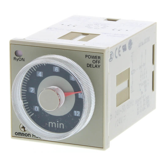
Solid-state Timer
DIN 48 x 48-mm Multifunctional Timer Series
Conforms to EN61812-1 and EN60664-1
(VDE0110) 4 kV/2.
Conforms to EMC standards (EN50081-2 and
EN50082-2).
Broad Line-up of H3CR Series
H3CR-A
Multifunctional Timer
H3CR-A
11-pin model
H3CR-AS
H3CR-AP
H3CR-A8
8-pin model
H3CR-A8S
8-pin with
H3CR-A8E
instantaneous
contact output
model
Note: H3CR-AS, H3CR-A8S: Transistor output models
Solid-state Timer
H3CR-A
. . . . . . . . . . . . . . . . . . . . . . . . . . . . . . . . . . . . . . . . . . . . . . . . . . . . . . . . . . . .
H3CR-F
. . . . . . . . . . . . . . . . . . . . . . . . . . . . . . . . . . . . . . . . . . . . . . . . . . . . . . . . . . . .
H3CR-G
. . . . . . . . . . . . . . . . . . . . . . . . . . . . . . . . . . . . . . . . . . . . . . . . . . . . . . . . . . . .
H3CR-H
. . . . . . . . . . . . . . . . . . . . . . . . . . . . . . . . . . . . . . . . . . . . . . . . . . . . . . . . . . . .
Common to ALL Timers
Operation
. . . . . . . . . . . . . . . . . . . . . . . . . . . . . . . . . . . . . . . . . . . . . . . . . . . . . . . . . .
Accessories
Precautions
H3CR-F
Twin Timer
H3CR-F
H3CR-FN
11-pin model
H3CR-F-300
H3CR-FN-300
H3CR-F8
H3CR-F8N
8-pin model
H3CR-F8-300
H3CR-F8N-300
Contents
. . . . . . . . . . . . . . . . . . . . . . . . . . . . . . . . . . . . . . . . . . . . . . . . . . . . . . . .
. . . . . . . . . . . . . . . . . . . . . . . . . . . . . . . . . . . . . . . . . . . . . . . . . . . . . . . . .
Approved by UL and CSA.
Lloyds/NK approvals.
Six-language instruction manual provided.
H3CR
H3CR-G
Star-delta Timer
H3CR-G8L
8-pin model
H3CR-G8EL
H3CR
H3CR-H
Power OFF-delay Timer
11-pin model
H3CR-HRL
H3CR-H8L
8-pin model
H3CR-H8RL
4
23
29
36
45
47
51
3
Advertisement
Table of Contents

Related Manuals for Omron H3CR-A


Summary of Contents for Omron H3CR-A
- Page 1 Approved by UL and CSA. (VDE0110) 4 kV/2. Lloyds/NK approvals. Conforms to EMC standards (EN50081-2 and Six-language instruction manual provided. EN50082-2). Broad Line-up of H3CR Series H3CR H3CR-A H3CR-F H3CR-G H3CR-H Multifunctional Timer Twin Timer Star-delta Timer Power OFF-delay Timer...
-
Page 2: Ordering Information
H3CR-A H3CR-A Solid-state Timer H3CR-A DIN 48 x 48-mm State-of-the-art Multifunctional Timer A wider power supply range reduces the number of timer models kept in stock. A wide range of applications through six or four operating modes. Reduced power consumption. -
Page 3: Model Number Legend
24 to 48 VDC/VAC (50/60 Hz) Note: 1. Specify both the model number and supply voltage when ordering. Example: H3CR-A 100 to 240 VAC (50/60 Hz)/100 to 125 VDC Supply voltage 2. The operating modes are as follows A: ON-delay... -
Page 4: Specifications
B2: Flicker ON start (power supply start) B2: Flicker ON start Interval (power supply start) C: Signal ON/OFF-delay One-shot (power supply start) D: Signal OFF-delay E: Interval G: Signal ON/OFF-delay (Only for H3CR-A-300) J: One-shot (Only for H3CR-A-300) Pin type 11-pin 8-pin Input type No-voltage input... -
Page 5: Time Ranges
H3CR-A H3CR-A Time Ranges Note: When the time setting knob is turned below “0” until the point where the time setting knob stops, the output will operate instantaneously at all time range settings. Standard (0.05-s to 300-h) Models Time unit... - Page 6 2,000 VAC (1,000 VAC for H3CR-A S), 50/60 Hz for 1 min (between current-carrying metal parts and exposed non-current-carrying metal parts) 2,000 VAC (1,000 VAC for H3CR-A S), 50/60 Hz for 1 min (between control output terminals and operating circuit)
-
Page 7: Engineering Data
Operating mode display window Operating mode selector Select a mode from: Output indicator (orange) A, B, B2, C, D, and E (H3CR-A, -AP, and -AS) (Lit when output) A, B2, E and J (H3CR-A8, -A8S, and -A8E) G and J (H3CR-A-300) -
Page 8: Operation
H3CR-A H3CR-A Operation Block Diagrams H3CR-A/AS Zero setting Time range/ Operating AC (DC) input detection unit selectors mode selector circuit Oscillation Power supply Counting Output circuit circuit circuit circuit Indicator Reset input, start input, and gate input Input circuit circuit... - Page 9 H3CR-A H3CR-A H3CR-A8/A8S Zero setting Time range/ Operating AC (DC) input detection unit selectors mode selector circuit Oscillation Power supply Counting Output circuit circuit circuit circuit Indicator circuit Power-ON Output-ON indicator indicator H3CR-A8E Zero setting Time range/ Operating AC (DC) input...
-
Page 10: Timing Chart
H3CR-A H3CR-A Timing Chart Note: 1. The minimum power-opening time (“Rt”) is 0.1 s and the minimum pulse width is 0.05 s. 2. The letter “t” in the timing charts stands for the set time and “t–a” means that the period is less than the time set. - Page 11 H3CR-A H3CR-A Operating Timing chart mode Basic operation Signal Power OFF-delay Start Power Start Reset (see note) Output relay (NC) Output Output relay (NO) Note: Start input is valid and (Output indicator) re-triggerable while the Power indicator Timer is in operation.
- Page 12 H3CR-A H3CR-A H3CR-A8/-A8S Operating Timing chart mode ON-delay Power Basic operation Output relay (NC) Power Output relay (NO) (output Output indicator) Power indicator Flicker ON Power start Basic operation Output relay (NC) Power Output relay (NO) (output Output indicator) Power...
- Page 13 H3CR-A H3CR-A H3CR-A8E Operating Timing chart mode ON-delay Power Output relay (NC) Output relay Basic operation (NO) (output indicator) Instantaneous Power output relay (NC) Instantaneous output relay (NO) Output Power indicator Flicker ON Power start Output relay (NC) Basic operation...
- Page 14 H3CR-A H3CR-A Dimensions Note: All units are in millimeters unless otherwise indicated. H3CR-A H3CR-AP 66.6 H3CR-AS 52.3 39 dia. 44.8 x 44.8 11 pins H3CR-A8 H3CR-A8S H3CR-A8E 66.6 52.3 44.8 x 44.8 39 dia. 8 pins Dimensions with Set Ring 16.5...
-
Page 15: Installation
H3CR-A H3CR-A Installation Terminal Arrangement Note: The delayed contact of conventional Timers was indicated as The contact symbol of the H3CR-A is indicated as because its operating mode is six multi-modes (four multi-modes for the H3CR-A8). 11-pin Models 8-pin Models... -
Page 16: Input Connections
H3CR-A H3CR-A Input Connections H3CR-A/-AS The inputs of the H3CR-A/-AS are no-voltage (short-circuit or open) inputs. No-voltage Inputs No-contact Input Contact Input No-contact Input (Connection to NPN open (Connection to a voltage collector output sensor.) output sensor.) 12 to 24 VDC... -
Page 17: Voltage Inputs
H3CR-A H3CR-A H3CR-AP The start input of the H3CR-AP is voltage input. (Voltage imposition or open) Voltage Inputs No-contact Input No-contact Input Contact Input (Connection to PNP open (Connection to NPN open collector output sensor) collector output sensor) 12 to 24 VDC... -
Page 18: Application Examples
H3CR-A H3CR-A Application Examples A Mode: ON-delay ON-delay operation (A mode) is a basic mode. 1. Power-ON Start/Power-OFF Reset 3. Control of Integrated Time with Gate Signal The Power-ON start/Power-OFF reset operation is a standard oper- With a gate signal, the Power-ON start operation and Signal start ating method. -
Page 19: C Mode: Signal On/Off-Delay
H3CR-A H3CR-A 2. Signal Start/Signal Reset (in B Mode) 2. Signal-ON-OFF Start/Instantaneous Operation/Time-limit Reset If there is an abnormal signal, flashing starts. When the abnormal condition is restored, a reset signal stops the display flashing. Power (2 and 10) Power (2 and 10) - Page 20 H3CR-A H3CR-A 2. Signal Start/Instantaneous Operation/Time-limit Reset 2. Signal Start/Instantaneous Operation/Time-limit Reset This function is useful for the repetitive control such as the filling of liquid for a specified period after each Signal start input. Power (2 and 10) Start (2 and 6)
-
Page 21: Ordering Information
H3CR-F H3CR-F Solid-state Twin Timers H3CR-F DIN 48 x 48-mm Twin Timers Wide power supply ranges of 100 to 240 VAC and 48 to 125 VDC respectively. Independent ON- and OFF-time settings. Further- more, combinations of long ON- or OFF-time and short OFF- or ON-time settings are possible. -
Page 22: Specifications
H3CR-F H3CR-F Accessories (Order Separately) Name/specifications Models Flush Mounting Adapter g dap e Y92F-30 Y92F-73 Y92F-74 Mounting Track 50 cm (l) x 7.3 mm (t) PFP-50N 1 m (l) x 7.3 mm (t) PFP-100N 1 m (l) x 16 mm (t) PFP-100N2 End Plate PFP-M... - Page 23 H3CR-F H3CR-F Ratings Rated supply voltage (see note) 100 to 240 VAC (50/60 Hz),12 VDC, 24 VAC/DC (50/60 Hz), 48 to 125 VDC Operating voltage range 85% to 110% of rated supply voltage; 90% to 110% with 12-VDC models Power reset Minimum power-opening time: 0.1 s Power consumption 100 to 240 VAC: approx.
-
Page 24: Engineering Data
H3CR-F H3CR-F Engineering Data 10,000 5,000 1,000 Reference: A maximum current of 0.15 A can be switched at 125 VDC (cosf = 1) 30 VDC L/R = 7 ms and a maximum current of 0.1 A can be switched if L/R is 7 ms. In both cases, a life of 100,000 operations can be expected. -
Page 25: Timing Chart
H3CR-F H3CR-F Timing Chart : ON set time : OFF set time Operating mode Timing chart Flicker OFF start 0.1 s min. Power indicator Not lit indicator Not lit Output Output Flicker ON start 0.1 s min. Power indicator Not lit indicator Not lit Output... - Page 26 H3CR-F H3CR-F Dimensions Note: All units are in millimeters unless otherwise indicated. H3CR-F H3CR-FN 66.6 17.4 52.3 H3CR-F-300 H3CR-FN-300 44.8 x 44.8 37 dia. 14 dia. R1.3 11 pins 17.4 66.6 H3CR-F8 52.3 H3CR-F8N H3CR-F8-300 H3CR-F8N-300 37 dia. 44.8 x 44.8 14 dia.
- Page 27 H3CR-G H3CR-G Solid-state Star-delta Timer H3CR-G DIN 48 x 48-mm Star-delta Timer A wide star-time range (up to 120 seconds) and star-delta transfer time range (up to 0.5 seconds). Ordering Information Outputs Supply voltage 8-pin models Time-limit contact 100 to 120 VAC H3CR-G8L 200 to 240 VAC Time-limit contact and instantaneous contact...
- Page 28 H3CR-G H3CR-G Accessories (Order Separately) Name/specifications Models Flush Mounting Adapter g dap e Y92F-30 Y92F-70 Y92F-71 Mounting Track 50 cm (l) x 7.3 mm (t) PFP-50N 1 m (l) x 7.3 mm (t) PFP-100N 1 m (l) x 16 mm (t) PFP-100N2 End Plate PFP-M...
- Page 29 H3CR-G H3CR-G Ratings Rated supply voltage 100 to 120 VAC (50/60 Hz), 200 to 240 VAC (50/60 Hz) Operating voltage range 85% to 110% of rated supply voltage Power reset Minimum power-opening time: 0.5 s Power consumption 100 to 120 VAC: approx. 6 VA (2.6 W) at 120 VAC 200 to 240 VAC: approx.
- Page 30 H3CR-G H3CR-G Engineering Data 10,000 5,000 1,000 Reference: A maximum current of 0.15 A can be switched at 125 VDC (cosf = 1) 30 VDC L/R = 7 ms and a maximum current of 0.1 A can be switched if L/R is 7 ms. In both cases, a life of 100,000 operations can be expected.
- Page 31 H3CR-G H3CR-G Operation Block Diagrams H3CR-G8L Star Star-delta operation transfer time time range selector selector Star-delta Star-delta Star operation Star Power transfer time transfer time time operation AC input Star operation supply oscillation counting oscillation time counting circuit Output circuit circuit circuit circuit...
- Page 32 H3CR-G H3CR-G Timing Chart t1: Star operation time setting t2: Star-delta transfer time Model Timing chart H3CR-G8L/-G8EL 0.5 s min. Power (2 – 7) Instantaneous output (1 – 3) (-E models) Star operation output (8 – 5) Delta operation output (8 – 6) Star operation indicator Not lit Delta operation indicator...
- Page 33 H3CR-G H3CR-G Dimensions Note: All units are in millimeters unless otherwise indicated. 78.0 63.7 39 dia. 44.8 x 44.8 8 pins Dimensions with Set Ring 16.5 42 dia. Time setting ring Panel cover Dimensions with Front Connecting Socket Dimensions with Back Connecting Socket P2CF-08- P3G-08 92.9...
- Page 34 H3CR-H H3CR-H Solid-state Power OFF-delay Timer H3CR-H DIN 48 x 48-mm Power OFF-delay Timer Long power OFF-delay times; S-series: up to 12 seconds, M-series: up to 12 minutes. Models with forced-reset input are available. 11-pin and 8-pin models are available. Ordering Information Input Output...
- Page 35 H3CR-H H3CR-H Accessories (Order Separately) Name/specifications Models Flush Mounting Adapter g dap e Y92F-30 Y92F-70 Y92F-71 Mounting Track 50 cm (l) x 7.3 mm (t) PFP-50N 1 m (l) x 7.3 mm (t) PFP-100N 1 m (l) x 16 mm (t) PFP-100N2 End Plate PFP-M...
- Page 36 H3CR-H H3CR-H Ratings Rated supply voltage (see note 1) 100 to 120 VAC (50/60 Hz), 200 to 240 VAC (50/60 Hz), 24 VAC/VDC (50/60 Hz), 48 VDC, 100 to 125 VDC Operating voltage range 85% to 110% of rated supply voltage No-voltage input (see note 2) ON-impedance: 1 kΩ...
- Page 37 H3CR-H H3CR-H Characteristics Accuracy of operating 0.2% FS max. ( 0.2% FS 10 ms max. in ranges of 0.6 and 1.2 s) time Setting error 5% FS 50 ms max. Operation start voltage 30 % max. of rated voltage Influence of voltage 0.2% FS max.
- Page 38 H3CR-H H3CR-H Engineering Data 10,000 5,000 1,000 Reference: A maximum current of 0.15 A can be switched at 125 VDC (cosf = 1) 30 VDC L/R = 7 ms and a maximum current of 0.1 A can be switched if L/R is 7 ms. In both cases, a life of 100,000 operations can be expected.
- Page 39 H3CR-H H3CR-H Operation Block Diagrams Without Reset Input (H3CR-H8L) Time range selector Power supply Oscillation Counting Output AC (DC) input circuit circuit circuit circuit Power failure Indicator Output detection circuit circuit indicator With Reset Input (H3CR-H8RL/-HRL) Time range selector Power supply Oscillation Counting Output...
- Page 40 H3CR-H H3CR-H Timing Chart Set time Rt: Minimum power ON time (S-series: 0.1 s min.; M-series: 2 s min.) Model Timing chart H3CR-H8L Power (see note) Output (1 – 3) Output (1 – 4) Output (8 – 6) Output (8 – 5) Output indicator Not lit...
- Page 41 H3CR-H H3CR-H Dimensions Note: All units are in millimeters unless otherwise indicated. H3CR-H8L H3CR-H8RL 78.0 63.7 39 dia. 44.8 x 44.8 8 pins H3CR-HRL 78.0 63.7 44.8 x 44.8 39 dia. 11 pins Dimensions with Back Connecting Socket Dimensions with Front Connecting Socket P3G-08/P3GA-11 P2CF-08- /P2CF-11- 92.9...
- Page 42 H3CR-H H3CR-H Installation Terminal Arrangement Note: DC models, including 24 VAC/DC models, have polarity. 8-pin Models Without Reset Input (H3CR-H8L) With Reset Input (H3CR-H8RL) Reset input (–) (–) Power supply Power supply Note: Leave terminal 3 open. Do not use them as relay terminals.
-
Page 43: Basic Setting
A time range (1.2, 3, 12, or 30/2.4, 6, 24, or 60 for H3CR-A -301) is selected with the time range selector at the lower left corner of the front panel, and the selected time range appears (in the window at the lower right part) within the plastic frame of the time setting knob. - Page 44 Use the time setting knob to set the desired time. Star-delta transfer time selector Using the Time Setting Ring for H3CR-A/-G Setting a Specific Time Limiting the Setting Range Mount the Panel Cover on the Timer, set the desired time with the Example: To set a range of 10 and 20 s.
- Page 45 H3CR H3CR Accessories (Order Separately) Note: The undermentioned is common for all H3CR models. Note: All units are in millimeters unless otherwise indicated. Flush Mounting Adaptor Panel Y92F-30 Panel Cutout 0.5 R max. +0.6 Note: The adapters for two or more timers mounted in a vertical line are different in –0 orientation from those mounted in a horizontal line.
- Page 46 H3CR H3CR Track Mounting/Front Connecting Socket P2CF-08 Eight, M3.5 x 7.5 sems 70 max. 35.4 Terminal Arrangement/ Two, 4.5 dia. Internal Connections holes Surface Mounting Holes (Top View) 50 max. Two, 4.5 dia. or two, M4 20.3 max. P2CF-08-E (Finger Safe Terminal Type) Conforming to VDE0106/P100 40 0.2 Eight,...
- Page 47 H3CR H3CR Back Connecting Socket Terminal Arrangement/ P3G-08 27 dia. Internal Connections (Bottom View) P3GA-11 Terminal Arrangement/ 27 dia. Internal Connections (Bottom View) 25.6 16.3 Finger Safe Terminal Cover Conforming to VDE0106/P100 Y92A-48G Twelve, 6.4 dia. holes (Attachment for P3G-08/P3GA-11 Socket) 47.7 x 47.7 48 x 48...
-
Page 48: Protective Cover
2. The Protective Cover cannot be mounted if the Panel Cover (sold separately) is used on the Timer. Y92A-48B Time Setting Ring/Panel Cover for H3CR-A/-G There are three types of Panel Covers (Y92P-48GL, Y92P-48GB, The Time Setting Ring and Panel Cover should be used as a pair. -
Page 49: Changing The Setting
Timer may break or malfunction. Provide supplementary basic isolation on the load side connected Do not use H3CR-A models (except for H3CR-A S) in flicker to the output so that reinforced isolation required by the EN61812-1 mode, or H3CR-F models at the lowest selector setting. Doing so will be ensured. - Page 50 Precautions (H3CR-A) Note: The undermentioned is common for all H3CR-A models. Power Supplies For the power supply of an input device of the H3CR-A /-A S/-AP, Input/Output use an isolating transformer with the primary and secondary wind- Relationship between Input and Power Supply ings mutually isolated and the secondary winding not grounded.
- Page 51 An appropriate input is applied to the input signal terminals of the another (refer to the figures below). H3CR-A /-A S when one of the input terminals is short-circuited with the common terminal (terminal 2) for the input signals. Never...
- Page 52 Output Short-circuit current If it is required that the output be turned on repeatedly with an inter- val of shorter than 3 s, consider use of the H3CR-A in mode D (sig- nal OFF-delay). H3CR-A Others If the H3CR-H is dropped or experiences some other kind of shock,...
- Page 53 H3CR H3CR...
- Page 54 H3CR H3CR...
- Page 55 To convert millimeters into inches, multiply by 0.03937. To convert grams into ounces, multiply by 0.03527. Cat. No. L084-E1-3 In the interest of product improvement, specifications are subject to change without notice. OMRON Corporation Industrial Automation Company Measuring and Supervisory Controls Division 28th Fl., Crystal Tower Bldg.,...