Table of Contents
Advertisement
Chipsmall Limited consists of a professional team with an average of over 10 year of expertise in the distribution
of electronic components. Based in Hongkong, we have already established firm and mutual-benefit business
relationships with customers from,Europe,America and south Asia,supplying obsolete and hard-to-find components
to meet their specific needs.
With the principle of "Quality Parts,Customers Priority,Honest Operation,and Considerate Service",our business
mainly focus on the distribution of electronic components. Line cards we deal with include
Microchip,ALPS,ROHM,Xilinx,Pulse,ON,Everlight and Freescale. Main products comprise
IC,Modules,Potentiometer,IC Socket,Relay,Connector.Our parts cover such applications as commercial,industrial,
and automotives areas.
We are looking forward to setting up business relationship with you and hope to provide you with the best service
and solution. Let us make a better world for our industry!
Contact us
Tel: +86-755-8981 8866 Fax: +86-755-8427 6832
Email & Skype: info@chipsmall.com Web: www.chipsmall.com
Address: A1208, Overseas Decoration Building, #122 Zhenhua RD., Futian, Shenzhen, China
Advertisement
Table of Contents

Related Manuals for Omron H3CR


Summary of Contents for Omron H3CR
- Page 1 Chipsmall Limited consists of a professional team with an average of over 10 year of expertise in the distribution of electronic components. Based in Hongkong, we have already established firm and mutual-benefit business relationships with customers from,Europe,America and south Asia,supplying obsolete and hard-to-find components to meet their specific needs.
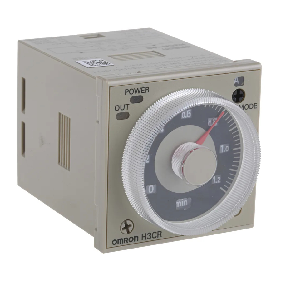
- Page 2 Solid-state Timer H3CR Please read and understand this catalog before purchasing the products. Please consult your OMRON representative if you have any questions or comments. Refer to Warranty and Application Considerations (page 52), and Safety Precautions (page 22, 44, 51).
-
Page 3: Model Number Structure
• Length of 75 mm or less when panel-mounted with a P3G-08 For the most recent information on models that have been certified for Socket (H3CR-A8E, 100 to 240 VAC, 100 to 125 VDC) safety standards, refer to your OMRON website. -
Page 4: Ordering Information
H3CR-A Ordering Information ■ List of Models Note: 1. Specify both the model number and supply voltage when ordering. Example: H3CR-A 100-240AC/100-125DC Supply voltage 2. The operating modes are as follows ON-delay D: Signal OFF-delay Flicker OFF start E: Interval... -
Page 5: Terminal Cover
Note: 1. The P2CF-@@-E has a finger-protection structure. Round crimp terminals cannot be used. Use forked crimp terminals. 2. The P3GA-11 and P3G-08 Socket can be used together with the Y92A-48G Terminal Cover to implement finger protection. 3. For details, refer to your OMRON website. Terminal Cover... -
Page 6: Specifications
Output category according to EN60947-5-2 for Timers with Transistor Outputs. * The internal circuits are optically isolated from the output. This enables universal application as NPN or PNP transistor. For details, refer to your OMRON website. ■ Time Ranges Note: When the time setting knob is turned below “0” until the point where the time setting knob stops, the output will operate instantaneously at all time range settings. - Page 7 H3CR-A ■ Ratings Rated supply voltage (See notes 1, 2, and 5.) 100 to 240 VAC (50/60 Hz)/100 to 125 VDC, 24 to 48 VAC (50/60 Hz)/12 to 48 VDC (24 to 48 VAC/VDC for H3CR-A8E) (See note 3.) Operating voltage range...
- Page 8 Approx. 90 g Note: 1. The value is ±5% FS +100 ms to −0 ms max. when the C, D, or G mode signal of the H3CR-AP is OFF. 2. The influence of voltage of the H3CR-A8E (24 to 48 VAC/12 to 48 VDC) is ±2.0% FS max. with a single-phase power supply with full- wave rectification.
- Page 9 H3CR-A Connections ■ Block Diagrams H3CR-A/-AS/-A-301 Zero setting AC (DC) input Time range/ Operating detection unit selectors mode selector circuit Power supply Oscillation Counting Output circuit circuit circuit circuit Indicator Reset input, start input, and gate input Input circuit circuit...
- Page 10 The timing operation is interrupted while the gate input is active. Outputs Control output Outputs are turned ON according to designated output mode when preset value is reached. Note: H3CR-AP incorporates start input only. Models H3CR-A8/-A8E/-A8S/-A8-301 do not have an input function.
- Page 11 The contact symbol of the H3CR-A is indicated as because its operating mode is eight multi-modes (five multi-modes for the H3CR-A8). 2. Do not use an empty terminal on the H3CR-AP/-AS/-A8S as a relay terminal or otherwise. 11-pin Models 8-pin Models...
- Page 12 H3CR-A ■ Input Connections H3CR-A/-AS/-A-301 The inputs of the H3CR-A/-AS/-A-301 are no-voltage (short-circuit or open) inputs. No-voltage Inputs No-contact Input Contact Input No-contact Input (Connection to a voltage (Connection to NPN open collector output sensor.) output sensor.) 12 to 24 VDC...
- Page 13 H3CR-A H3CR-AP The start input of the H3CR-AP is voltage input. (Voltage imposition or open) Voltage Inputs No-contact Input No-contact Input Contact Input (Connection to PNP open (Connection to NPN open collector output sensor) collector output sensor) 12 to 24 VDC...
-
Page 14: Operation
3. The letter "t" in the timing charts indicates the set time, and "t-a" means that the period is less than the set time. (t - a < 1) 4. H3CR-AP model incorporates start input only. As such, the power supply is reset. - Page 15 4. In J Mode, there will be only one output even if the start input is longer than the set time. Reset 5. H3CR-AP model incorporates start input only. As such, the power supply is reset. Output 6. Model H3CR-AS only has operation equivalent to time-limit relay contact: NO.
- Page 16 2. The letter "t" in the timing charts indicates the set time, and "t-a" means that the period is less than the set time. (t - a < 1) 3. Model H3CR-A8S only has operation equivalent to time-limit contact: NO.
- Page 17 H3CR-A H3CR-A8E Operating Timing chart mode ON-delay Power Output relay (NC) Output relay (NO) Basic operation (output indicator) Instantaneous Power output relay (NC) Instantaneous output relay (NO) Output (See Note 6) Power indicator t−a Rt t−a t t t t ...
- Page 18 Operating mode selector Select a mode from: Output indicator (orange) A, B, B2, C, D, E, G, and J (H3CR-A, -AP, and -AS) (Lit when output) A, B, B2, E and J (H3CR-A8, -A8S, and -A8E) Scale range display windows...
- Page 19 H3CR-A Dimensions Note: All units are in millimeters unless otherwise indicated. H3CR-A H3CR-AP H3CR-AS 66.6 H3CR-A-301 52.3 39 dia. 44.8 × 44.8 11 pins H3CR-A8 H3CR-A8S H3CR-A8E H3CR-A8-301 66.6 52.3 39 dia. 44.8 × 44.8 8 pins Dimensions with Set Ring Y92S-27/-28 (Order Separately) 16.5...
-
Page 20: Protective Cover
H3CR-A ■ Accessories (Order Separately) Protective Cover Hold-down Clip Y92A-48B Y92H-8 To use the Protective Cover with a flush mounting, use the Y92F-30 The Y92H-8 Hold-down Clip is attached to the PF085A socket. flush mounting adaptor. This Protective Cover cannot be used together with the Y92F-73/-74 flush mounting adaptor or the panel cover. - Page 21 H3CR-A Application Examples (H3CR-A) A Mode: ON-delay ON-delay operation (A mode) is a basic mode. 1. Power-ON Start/Power-OFF Reset 3. Control of Integrated Time with Gate Signal The Power-ON start/Power-OFF reset operation is a standard operating method. Gate signal processing (during input or a temporary timing stop) is possible with both power start and signal start.
- Page 22 H3CR-A 2. Signal Start/Signal Reset (in B Mode) 2. Signal-ON-OFF Start/Instantaneous Operation/Time-limit Reset If there is an abnormal signal, flashing starts. When the abnormal condition is restored, a reset signal stops the display flashing. Power (2 and 10) Power (2 and 10)
- Page 23 H3CR-A 2. Signal Start/Instantaneous Operation/ 2. Signal Start/Instantaneous Operation/ Time-limit Reset Time-limit Reset This function is useful for the repetitive control such as the filling of liquid for a specified period after each Signal start input. Power (2 and 10)
- Page 24 Note: The following precautions apply to all H3CR-A models. ■ Power Supplies ■ Input/Output For the power supply of an input device of the H3CR-A use an Relationship between Input and Power isolating transformer with the primary and secondary windings mutually isolated and the secondary winding not grounded.
- Page 25 NPN output type or a PNP (equivalent) output type. With the H3CR-AP, input wires must be as short as possible. If the floating capacity of wires exceeds 1,200 pF (approx. 10 m for cables Relationship between Input and Power with 120 pF/m), the operation will be affected.
- Page 26 MEMO...