Omron H5S Series Manual
Digital time switch
Hide thumbs
Also See for H5S Series:
- Instruction manual (72 pages) ,
- Datasheet (29 pages) ,
- Manual (20 pages)
Table of Contents
Advertisement
Quick Links
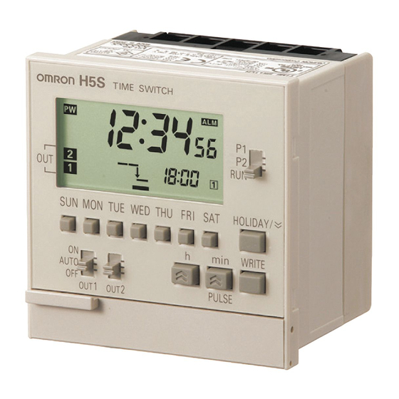
Digital Time Switch
H5S
Easier, More Convenient Time Switches, with
New 4-circuit Output and Yearly Models in
Addition to 2-circuit Weekly Models
• Independent Day Keys provide easier operation.
• Temporary holiday setting function makes it easy to turn OFF
output for holidays and non-operating days.
• Settings can be made even with the Time Switch turned OFF.
• Test mode enables easy program checking.
• Complies with EMC Directives, UL/CSA, and other safety
standards.
• Includes summer time (DST) adjustment.
Yearly models also offer automatic switching to DST.
• Set value can be changed both upward and downward for
speedier setting.
• Integrated temperature compensation circuit helps keep
accurate time over a wide temperature range. (See note 1.)
• Includes time counter and total counter functions with alarm
indicator. (See note 2.)
• Bank function allows program switching by an external input.
(See note 3.)
• New 4-circuit output models with a compact, 72 × 72-mm DIN
size added to the series.
Note: 1. Available only on yearly models.
2. Available only on 2-circuit models.
3. Available only on weekly models.
Features
Easier and More Convenient to Use
■ Simple Setting
Independent Day Keys make setting easy.
■ Convenient Functions
Time Counter/Total Counter Functions (See note.)
This function makes it possible to monitor the total time that a load
has been applied, or the total number of operating cycles. It allows
the Time Switch to be used for managing maintenance.
Downloaded from
Elcodis.com
electronic components distributor
Up/down set value changing
for speedy setting.
Temporary holidays
(non-operating days)
are also easy to set.
Weekly models: Specify the day.
Yearly models: Specify the date.
With alarm indicator
Shows total lamp ON time
Time Adjustment Function (See note.)
The time can be set to 00 min 00 s by using an external input. The
times on multiple Time Switches can also be easily synchronized.
Synchronized!
Slave
Master
Note: Equipped on 2-circuit models.
CSM_H5S_DS_E_3_1
Slave
1
Advertisement
Table of Contents

Related Manuals for Omron H5S Series


Summary of Contents for Omron H5S Series
- Page 1 Digital Time Switch CSM_H5S_DS_E_3_1 Easier, More Convenient Time Switches, with New 4-circuit Output and Yearly Models in Addition to 2-circuit Weekly Models • Independent Day Keys provide easier operation. • Temporary holiday setting function makes it easy to turn OFF output for holidays and non-operating days.
-
Page 2: Model Number Structure
More Applications on New Series Models Yearly Models 4-circuit Models Automatic Program Switching by Seasons Space-saving, Economical 4-circuit Models Added to the Series The yearly operation can be set to automatically change the weekly program depending on the season. (See note.) The new 4-circuit models are 72 ×... -
Page 3: Ordering Information
Ordering Information ■ List of Models Control cycle Number of outputs Mounting method Supply voltage Models Weekly 2 circuits Flush mounting 100 to 240 VAC H5S-WB2 24 VDC H5S-WB2D Surface mounting/ 100 to 240 VAC H5S-WFB2 track mounting 24 VDC H5S-WFB2D Yearly 2 circuits... - Page 4 ■ Characteristics Item Weekly 2-circuit Models Yearly 2-circuit Models Yearly 4-circuit Models (H5S-W@2) (H5S-Y@2) (H5S-Y@4) ±0.01%±0.05 s max. (See note 1.) Accuracy of operating The ±0.01% value applies to the set time interval. time Setting error Influence of voltage Influence of temperature ±15 s per month (at 25°C) ±15 s per month (at −10 to 45°C), ±20 s per month (at 45 to 55°C) Cyclic error...
- Page 5 ■ Operation Item Weekly 2-circuit Models Yearly 2-circuit Models Yearly 4-circuit Models (H5S-W@2) (H5S-Y@2) (H5S-Y@4) Operation method Digital quartz Operation period 1 week (7 days) 1 year (with integrated calendar to 2099) Display • Day, hrs (switchable between 24-hr indication and a.m./p.m. 12-hr indication), minutes, seconds (0.00 to 23:59, 0.00 to 11:59 a.m., 0.00 to 11:59 p.m.) •...
- Page 6 Item Weekly 2-circuit Models (H5S-W@2) Yearly 2-circuit Models (H5S-Y@2) Yearly 4-circuit Models (H5S-Y@4) Checking the Consecutively displays the times when the output is set to turn ON and OFF for one day in the sequence in which the Time settings Switch is to operate.
- Page 7 Connections ■ Terminal Arrangement H5S-@A@/-@B@ Flush Mounting Models Two-circuit Models Four-circuit Models Output 2 Output 3 Output 2 Input Output 4 (Rear View) (Rear View) − − ∼ ∼ ∼ ∼ Power Output 1 Power Output 1 source source H5S-@FA@/-@FB@ Surface Mounting Models Two-circuit Models Four-circuit Models Output 3...
- Page 8 Nomenclature Front Panel (with Cover Open) Key Operations Functions Weekly Two-circuit Models Two-circuit Models P1: Circuit (output) 1 Setting mode P2: Circuit (output) 2 Setting mode RUN: RUN mode Four-circuit Models 1. Mode PRGM: Setting mode (allows use of the Select Program Key Switch to set the circuit (output) number) RUN: RUN mode...
- Page 9 Display Display Description Weekly Two-circuit Models 4. Main display Function 3. Summer time indicator 5. Pulse width unit indicator Lights when power is supplied to the Time 1. Power indicator 6. Total value alarm Switch. indicator 2. AM/PM indicator When 12-hour display is selected, either AM 7.
- Page 10 Dimensions Note: All units are in millimeters unless otherwise indicated. Digital Time Switch Flush Mounting Model Panel Cutout (53.2) Two terminal covers (included) H5S-@A@/-@B@ Four M3 x 8 screws (included) for mounting the terminal covers (75 × 75) 67.6 × 67.6 TIME SWIT CH Two M4 x 12 screws (included) (12.5)
- Page 11 ■ Accessories (Order Separately) Protective Cover DIN Track Mounting Large Terminal Covers Base Y92A-72H (two per set) Y92A-72C Y92F-90 Note: The DIN Track Mounting Base can be Note: The Large Terminal Cover can be used only with the surface mounting used only with the surface mounting models (H5S-@FA@/-@FB@).
-
Page 12: Safety Precautions
Safety Precautions 12.Separate equipment that produces input signals, input signal !CAUTION wiring, and the Time Switch from noise-generating sources and high-voltage lines containing noise. Minor injury by electric shock may occasionally occur. Do 13.Do not connect more than two crimp terminals to each Time not touch any of the terminals while power is being Switch terminal. -
Page 13: Basic Use
■ EN/IEC Standards • The relationship between load current and ambient air temperature is shown by the range below for 2-circuit models. • The insulation system between the power supply circuit and input- output terminals provides basic insulation. Therefore connect the output terminals only to circuits without exposed conductive parts. - Page 14 Time Adjustment (Weekly Models) Time Adjustment (Yearly Models) Weekly, 2 Circuits Yearly, 2 Circuits Yearly, 4 Circuits Example: Set the current time to Saturday 17:28. Example: Set the current time to 17:28 on August 15, 2006. 1. Set the Mode 1.
- Page 15 Ordinary Timer Operation Multiple-day Operation 1 Weekly, 2 Circuits Yearly, 2 Circuits Yearly, 4 Circuits Weekly, 2 Circuits Yearly, 2 Circuits Yearly, 4 Circuits Example: ON at 8:30 and OFF at 17:15 on Monday through Friday. Example: ON continuously from 8:30 on Monday to 17:15 on Friday. 8:30 17:15 8:30 17:15 8:30 17:15 8:30 17:15 8:30 17:15 8:30 17:15...
- Page 16 Multiple-day Operation 2 Pulse-output Operation Weekly, 2 Circuits Yearly, 2 Circuits Yearly, 4 Circuits Weekly, 2 Circuits Yearly, 2 Circuits Yearly, 4 Circuits Example: ON at 22:00 from Monday through Friday and OFF at 8:00 Example: ON for 30 seconds at 8:25 am from Monday through each following morning.
-
Page 17: Cyclic Operation
Cyclic Operation Weekly, 2 Circuits Yearly, 2 Circuits Yearly, 4 Circuits Example: ON for 5 minutes and OFF for 1 hour 55 minutes repeatedly from 8:00 to 19:00 on Sunday. Start Stop 5 min 1 h 55 min 8:00 19:00 1. -
Page 18: Clearing The Settings
Clearing the Settings About Yearly Programs Weekly, 2 Circuits Yearly, 2 Circuits Yearly, 4 Circuits Yearly, 2 Circuits Yearly, 4 Circuits Yearly programs in addition to ordinary weekly programs can be set Partial clearing for 2- and 4-circuit yearly models. 1. - Page 19 Yearly Timer Operation Yearly Pulse-output Operation Yearly, 2 Circuits Yearly, 4 Circuits Yearly, 2 Circuits Yearly, 4 Circuits Example: ON at 18:00 and OFF at 22:15 on March 25 every year. Example: To produce output for 2 minutes at 18:00 from March 25 to April 9.
-
Page 20: Convenient Functions
Convenient Functions Setting Temporary Holidays (Weekly) Setting Temporary Holidays (Yearly) Weekly, 2 Circuits Yearly, 2 Circuits Yearly, 4 Circuits Temporary holidays (non-operating days) can be easily set. Temporary* holidays (non-operating days) can be set simply by specifying dates. The holidays will be OFF in both the weekly and Because the setting is automatically cleared after the set holiday has yearly programs. -
Page 21: Checking The Settings
Program Check Function Day Override Operation Weekly, 2 Circuits Yearly, 2 Circuits Yearly, 4 Circuits Weekly, 2 Circuits The days and times when output is set to turn ON and OFF over the Operation for one day can be temporarily (for only one week) course of one week can be displayed in the sequence in which the executed on another day. -
Page 22: Display Switching
Switching between 12-hour and 24- Override and Automatic Return hour display Operation Weekly, 2 Circuits Yearly, 2 Circuits Yearly, 4 Circuits Weekly, 2 Circuits Yearly, 2 Circuits Yearly, 4 Circuits Helps to cope with sudden schedule changes without having to Each time is pressed for 2 s or more in RUN mode, the current revise the existing program. -
Page 23: Using Advanced Functions
Using Advanced Functions About Advanced Functions Time Counter/Total Counter Display (F2, F3, F4) Set the advanced functions as required to perform more advanced operation. Outlines of the advanced functions are provided on the Yearly, 2 Circuits Yearly, 2 Circuits following pages. Refer to the Instruction Manual enclosed with the H5S for details. - Page 24 Time Adjustment Input Function (F2) Bank Switching (F2) Weekly, 2 Circuits Yearly, 2 Circuits Weekly, 2 Circuits The time can be set to 00 min 00 s at the same time as external input Two groups (banks) of programs can be registered with the Time is applied.
- Page 25 Period of Season (F9) Date Format Selection (F5) Shaded portion indicates Yearly, 2 Circuits Yearly, 4 Circuits blinking of the indicator. The displayed date format is selectable between “month. day” and 1. Press to select the desired “day. month”. season. Parameters : “month.
- Page 26 Summer Time Schedule Selection (F7) Yearly, 2 Circuits Yearly, 4 Circuits The time and date when the Time Switch automatically switches to and from summer time can be selected with reference to the following regions. Parameters Regions Summer time start Summer time end date and time date and time...
- Page 27 Warranty and Limitations of Liability WARRANTY OMRON's exclusive warranty is that the products are free from defects in materials and workmanship for a period of one year (or other period if specified) from date of sale by OMRON. OMRON MAKES NO WARRANTY OR REPRESENTATION, EXPRESS OR IMPLIED, REGARDING NON-INFRINGEMENT, MERCHANTABILITY, OR FITNESS FOR PARTICULAR PURPOSE OF THE PRODUCTS.