
Related Manuals for Samson TROVIS 5573


Summary of Contents for Samson TROVIS 5573
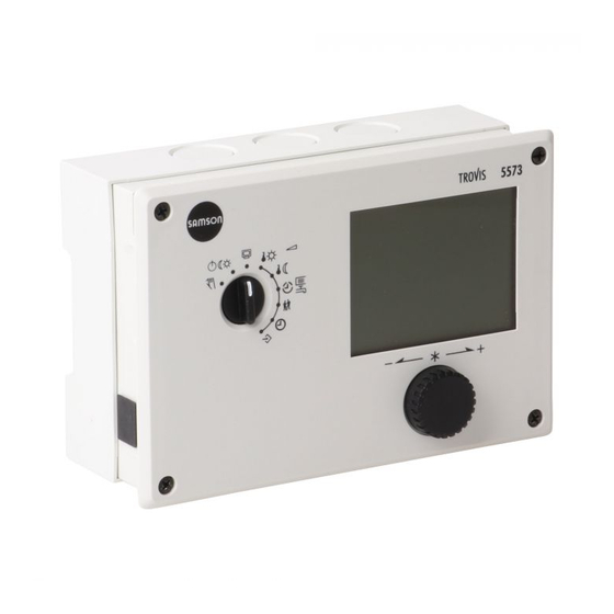
- Page 1 Automation System TROVIS 5500 Heating and District Heating Controller TROVIS 5573 Mounting and Operating Instructions EB 5573 EN Firmware version 1.82 ® Edition November 2008 Electronics from SAMSON...
- Page 2 Moreover, we do not guarantee that the buyer can use the product for an in- tended purpose. SAMSON rejects any liability for claims by the buyer, especially claims for compensation including lost profits or any other financial loss, except the damage was caused intentionally or by gross negligence.
-
Page 3: Table Of Contents
Contents ContentsPage Operation ....... 6 Operating controls ......6 1.1.1 Rotary pushbutton . - Page 4 Contents Flash adaptation ......56 5.8.1 Flash adaptation without outdoor sensor (room temperature dependent) . 57 Adaptation .
- Page 5 Contents Error status register ......79 Sending text messages in case of error ....80 Communication .
-
Page 6: Operation
Operation Operation The controller is ready for use with the default temperatures and operating schedules. On start-up, the current time and date need to be set at the controller (–> section 1.5). Operating controls The operating controls are located in the front panel of the controller. 1.1.1 Rotary pushbutton Rotary pushbutton –... -
Page 7: Operating Modes
Operation Operating modes Day mode (rated operation) : Regardless of the programmed times-of-use and summer mode, the set points relevant for rated operation are used by the controller. : Regardless of the programmed times-of-use, the set points Night mode (reduced operation) relevant for reduced operation are used by the controller. -
Page 8: Display
Operation Display The display indicates the time as well as information about the operation of the controller when the rotary switch is at the normal position (information level). The times-of-use together with temperatures of the various control circuits can be viewed on the display by turning the rotary pushbutton. -
Page 9: Opening The Information Level
Operation Opening the information level At the normal switch position (information level), the time, date, public holidays and vaca- tion periods as well as the temperatures measured by the connected sensors and their set points can be retrieved and displayed. Note: Data can also be viewed in the operating level (manual mode). -
Page 10: Setting The Controller Time
Operation Setting the controller time The current time and date need to be set immediately after start-up and after a power failure of more than 24 hours has occurred. This is the case when the time blinks on the display. Proceed as follows: Turn the rotary switch to (controller time). -
Page 11: Setting The Times-Of-Use
Operation Setting the times-of-use Three times-of-use can be set for each day of the week. Range of values Parameters Period/day 1–7 1–7, 1, 2, 3, 4, 5, 6, 7 with 1–7 = every day, 1 = Monday, 2 = Tuesday, ..., 7 = Sunday Start first time-of-use 6:00 0:00 to 24:00h;... - Page 12 Operation Select period/day for which the times-of-use are to be valid [q]: 1–7 = every day, 1 = Monday, 2 = Tuesday, ..., 7 = Sunday Activate editing mode for period/day [ ]. Display: START , blink. Edit start time [q]. (in steps of 15 minutes) Confirm start time [ ].
-
Page 13: Setting The Party Mode
Operation Setting the party mode Using the Party mode function, the controller continues or activates the day mode during the time when the party timer is active, regardless of the programmed times-of-use. When the party timer has elapsed, the party mode timer is reset to 00:00. Range of values Parameter Continue/activate rated operation... -
Page 14: Activating The Extended Information Level
Operation Activating the extended information level If the extended information level is activated, further information can be viewed after the listed data points: Public holidays (can be changed, see section 1.8.1) Vacation periods (can be changed, see section 1.8.2) Valve positions Switching states of the binary inputs InFo 2: After confirming the level [ ] the following data appear in the sequence shown be- low:... -
Page 15: Setting Public Holidays
Operation 1.8.1 Setting public holidays On public holidays, the times-of-use specified for Sunday apply. A maximum of 20 public holidays may be entered. Level / Range of values Parameter Public holidays – Extended information level/ 01.01 to 31.12 Proceed as follows: In the extended information level (normal switch position ) select data point for public holidays [q]. -
Page 16: Setting Vacation Periods
Operation 1.8.2 Setting vacation periods During vacation periods, the controller constantly remains in reduced operation. A maximum of 10 vacation periods can be entered. Each vacation period can be separately assigned to the heating circuits Rk1, Rk2 and/or the DHW circuit. Parameter Level / Range of values Vacation period (START, STOP) - Page 17 Operation Note: Vacation periods can also be set in PA5 parameter level (–> section 2.3). Deleting vacation periods: Under data point for vacation periods, select the start date of the period you wish to de- lete [q]. Confirm selection [ ]. Select –...
-
Page 18: Entering Day And Night Set Points
Operation Entering day and night set points The desired room temperature for the day ( Day set point ) and a reduced room temperature for the night ( Night set point ) can be entered in the controller for the heating circuits. In the DHW circuit, the temperature you wish the DHW to be heated to can be set. - Page 19 (start-up, see section 2) PA1/CO1: Rk1 (heating circuit 1) PA2/CO2: Rk2 (heating circuit 2) PA4/CO4: DHW circuit PA5/CO5: System-wide parameters PA6/CO6 Modbus communication Anl: System code number Fig. 2 · Level structure of TROVIS 5573 EB 5573 EN...
-
Page 20: Start-Up
Start-up Start-up The modifications of the controller configuration and parameter settings described in this sec- tion can only be performed after the valid key number has been entered. The valid key number for initial start-up can be found on page 123. To avoid unauthorized use of the key number, remove the page or make the key number unreadable. -
Page 21: Activating And Deactivating Functions
Start-up Activating and deactivating functions A function is activated or deactivated in the associated function block. The numbers 0 to 24 in the top row of the display represent the respective function block numbers. When a configura- tion level is opened, the activated function blocks are indicated by a black square on the right-hand side below the function block number. - Page 22 Start-up 10. Confirm settings [ ]. If the function block is not closed, further function block parameters can be adjusted. Proceed as follows: Select function block parameter [q]. Confirm function block parameter [ ]. If applicable, the next function block parameter is displayed. Confirm all parameters to exit the opened function block.
-
Page 23: Changing Parameters
Start-up Changing parameters Depending on the set system code number and the activated functions, not all parameters listed in the parameter list in the Appendix (–> section 12.2) might be available. The parameters are grouped by topics: PA1: Rk1 (Heating circuit 1) PA2: Rk2 (Heating circuit 2) PA3: Not applicable PA4: DHW heating... -
Page 24: Calibrating Sensors
Start-up Calibrating sensors The controller is designed for the connection of Pt 1000 sensors. The resistance values of the Pt 1000 sensors can be found on page 112. If the temperature values displayed at the controller differ from the actual temperatures, the measured values of all connected sensors can be readjusted. -
Page 25: Resetting To Default Values
Start-up Storage tank sensor SF1 Storage tank sensor SF2 Storage tank sensor of the solar circuit SF2 Display measured value [ ]. “°C” blinks. 10. Correct measured value [q]. Read the actual temperature directly from the thermometer at the point of measurement and enter this value as the reference temperature. -
Page 26: Manual Mode
Manual mode Manual mode Switch to manual mode to configure all outputs, refer to wiring diagram (-> section 11). NOTICE The frost protection does not function when the controller is in manual mode. Proceed as follows: Turn the rotary switch to (manual level). -
Page 27: Systems
Systems Systems 21 different hydraulic schematics are available. The systems can be configured both as primary and secondary systems. The fundamental hy- draulic differences between a primary and a secondary system are illustrated in Fig. 3. 1. mixing valve replaces the heat exchanger in the heating/DHW circuit. 2. - Page 28 Systems Boiler systems: Single-stage boiler systems can be configured to include any system whose heating circuits and DHW circuit include just one heat exchanger. These systems are Anl 1.0, 1.5, 1.6, 2.x, 3.0, 3.5, 4.0 and 4.1. The boiler can be controlled by an on/off output (CO1 -> F12 - 0). Boiler single-stage RüF1...
- Page 29 Systems System Anl 1.0 RüF1 Default settings CO1 -> F01 - 0 (without RF1) CO1 -> F02 - 1 (with AF1) CO1 -> F03 - 1 (with RüF1) EB 5573 EN...
- Page 30 Systems Systems Anl 1.1 to 1.3 heating Unfold back cover! RüF1 RF1 System Anl 1.1 Anl 1.2 Anl 1.3 Type of DHW heating Type 1 Type 2 Type 3 XX = Integration of flow sensor VF4 Possible Possible – ZP integration with –...
- Page 31 Systems System Anl 1.5 RüF1 Default settings CO1 -> F03 - 1 (with RüF1) CO4 -> F01 - 1 (with SF1) CO4 -> F02 - 0 (without SF2) EB 5573 EN...
- Page 32 Systems System Anl 1.6 RüF1 System Anl 1.6 Anl 1.6 with pre-control without pre-control Integration of VF4, UP1 Possible Not possible ZP integration with Possible Possible CO4 -> F10 - 1 (broken line) VF1 takes the position of VF4; RüF1 is to be installed in the heat Note –...
- Page 33 Systems System Anl 1.9 RüF2 Default settings CO4 -> F01 - 0 (without SF1) CO4 -> F03 - 0 (without RüF2) EB 5573 EN...
- Page 34 Systems System Anl 2.0 SLP (RK2) RüF1 Default settings CO1 -> F01 - 0 (without RF1) CO1 -> F02 - 1 (with AF1) CO1 -> F03 - 1 (with RüF1) CO4 -> F01 - 1 (with SF1) CO4 -> F02 - 0 (without SF2) EB 5573 EN...
- Page 35 Systems Systems Anl 2.1 to 2.3 heating Unfold back cover! RüF1 System Anl 2.1 Anl 2.2 Anl 2.3 Type of DHW heating Type 1 Type 2 Type 3 XX = Integration of VF4 Not possible Possible – ZP integration with –...
- Page 36 Systems System Anl 3.0 RüF2 RüF1 Default settings CO1 -> F02 - 1 (with AF1) CO1 -> F03 - 1 (with RüF1) CO2 -> F01 - 0 (without RF2) CO2 -> F03 - 0 (without RüF2) EB 5573 EN...
- Page 37 Systems System Anl 3.5 RK1/Y1 RüF1 Closed control loop and UP1 are only active during the processing Note for an external demand Default settings CO1 -> F03 - 1 (with RüF1) EB 5573 EN...
- Page 38 Systems System Anl 4.0 RüF2 RüF1 Default settings CO1 -> F01 - 0 (without RF1) CO1 -> F02 - 1 (with AF1) CO1 -> F03 - 1 (with RüF1) CO2 -> F01 - 0 (without RF2) CO2 -> F03 - 0 (without RüF2) EB 5573 EN...
- Page 39 Systems System Anl 4.1 RüF2 RüF1 Default settings CO1 -> F01 - 0 (without RF1) CO1 -> F02 - 1 (with AF1) CO1 -> F03 - 1 (with RüF1) CO2 -> F01 - 0 (without RF2) CO2 -> F03 - 0 (without RüF2) CO4 ->...
- Page 40 Systems System Anl 4.5 RüF2 RüF1 Default settings CO1 -> F01 - 0 (without RF1) CO1 -> F02 - 1 (with AF1) CO1 -> F03 - 1 (with RüF1) CO2 -> F01 - 0 (without RF2) CO2 -> F03 - 0 (without RüF2) CO4 ->...
- Page 41 Systems System Anl 10.0 RüF2 RüF1 Default settings CO1 -> F01 - 0 (without RF1) CO1 -> F02 - 1 (with AF1) CO1 -> F03 - 1 (with RüF1) CO2 -> F01 - 0 (without RF2) CO2 -> F03 - 1 (with RüF2) EB 5573 EN...
- Page 42 Systems System Anl 11.0 RK1 RK2 RüF1 RüF2 VF1 UP1 Default settings CO1 -> F01 - 0 (without RF1) CO1 -> F02 - 1 (with AF1) CO1 -> F03 - 1 (with RüF1) CO4 -> F03 - 0 (without RüF2) EB 5573 EN...
- Page 43 Systems System Anl 11.1 RüF2 VF2 UP1 RK1 RüF1 RF1 Default settings CO1 -> F01 - 0 (without RF1) CO1 -> F02 - 1 (with AF1) CO1 -> F03 - 1 (with RüF1) CO4 -> F01 - 1 (with SF1) CO4 ->...
- Page 44 Systems System Anl 11.2 RüF1 RüF2 Default settings CO1 -> F01 - 0 (without RF1) CO1 -> F02 - 1 (with AF1) CO1 -> F03 - 1 (with RüF1) CO4 -> F01 - 1 (with SF1) CO4 -> F02 - 1 (with SF2) CO4 ->...
- Page 45 Systems System Anl 11.9 RüF2 RüF1 Default settings CO1 -> F01 - 0 (without RF1) CO1 -> F02 - 1 (with AF1) CO1 -> F03 - 1 (with RüF1) CO4 -> F01 - 0 (without SF1) CO4 -> F03 - 0 (without RüF2) EB 5573 EN...
-
Page 46: Functions Of The Heating Circuit
Functions of the heating circuit Functions of the heating circuit Which controller functions are available depends on the selected system code number (Anl). Weather-compensated control When weather-compensated control is used, the flow temperature is controlled according to the outdoor temperature. The heating characteristic in the controller defines the flow temperature set point as a function of the outdoor temperature (–>... -
Page 47: Gradient Characteristic
Functions of the heating circuit 5.1.1 Gradient characteristic Basically, the following rule applies: a decrease in the outdoor temperature causes the flow tem- perature to increase in order to keep the room temperature constant. By varying the parameters Gradient and Level , you can adapt the characteristic to your individ- ual requirements: The gradient needs to be increased if the room temperature [°C]... - Page 48 Functions of the heating circuit Outside the times-of-use, reduced set points are used for control: The reduced flow set point is calculated as the difference between the adjusted values for Day set point (rated room temperature) and Night set point (reduced room temperature). The Max.
-
Page 49: 4-Point Characteristic
Functions of the heating circuit 5.1.2 4-point characteristic [˚C] P1 to P4 Points 1 to 4 Flow temperature VLmax Outdoor temperature ---min Min. t ---max Max. t 4-point characteristic Reduced 4-point characteristic VLmin –5 –10 –15 –20 [˚C] Fig. 6 · 4-point characteristic The 4-point characteristic allows you to define your own heating characteristic. -
Page 50: Fixed Set Point Control
Functions of the heating circuit Parameter level / Range of values Parameters Flow Point 1 70.0 °C PA1, 2 / 5.0 to 130.0 °C temperature Point 2 55.0 °C Point 3 40.0 °C Point 4 25.0 °C Reduced flow Point 1 60.0 °C PA1, 2 / 5.0 to 130.0 °C temperature... -
Page 51: Underfloor Heating/Drying Of Jointless Floors
Functions of the heating circuit Underfloor heating/drying of jointless floors Using function block setting CO1, 2 -> F05 - 1, the respective heating circuit is configured as an underfloor heating circuit. In doing so, the controller at first only limits the value ranges of the heating characteristic gradient and the maximum flow temperature in PA1, 2 parameter levels: Value range of the gradient: 0.2 to 1.0 Value range of the maximum flow temperature: 5 to 50 °C... -
Page 52: Deactivation Depending On Outdoor Temperature
Functions of the heating circuit A power failure while the drying function is active or when STOP appears on the display auto- matically leads to the drying function restarting from the beginning. In systems in which the drying function had to be interrupted due to DHW heating (e.g. Anl 2.1), storage tank charging does not occur while the drying function is active, provided it is not used for frost protection of the storage tank. -
Page 53: Ot Activation Value In Rated Operation
Functions of the heating circuit The valve is closed and the pump is switched off after t = 2 x valve transit time. When the out- door temperature falls below this value (less 0.5 °C hysteresis), heating operation is restarted immediately. -
Page 54: Delayed Outdoor Temperature Adaptation
Functions of the heating circuit Note: Summer mode only becomes effective when the controller is in automatic mode ( ). Delayed outdoor temperature adaptation The calculated outdoor temperature is used to determine the flow temperature set point. The heat response is delayed when the outdoor temperature either decreases, increases or in- creases and decreases. -
Page 55: Optimization
Terminal 9 Terminal 10 Fig. 7 · Wiring plan for Type 5257-5 Room Panel to TROVIS 5573 for Rk1 or Rk2 With an activated room sensor, the measured room temperature is displayed when the re- mote operation is connected and activated. Nevertheless, it is not used for control unless the Optimization, Adaptation or Flash adaptation functions have been activated. -
Page 56: Flash Adaptation
Functions of the heating circuit Note: Direct sunshine can cause the room temperature to increase and thus result in the premature de- activation of the heating system. When the room temperature decreases while the heating system is shortly outside its times-of-use, this can prematurely cause the controller to heat up to the Day set point. -
Page 57: Flash Adaptation Without Outdoor Sensor (Room Temperature Dependent)
Functions of the heating circuit Configuration Functions Room sensors RF1/2 CO1, 2 -> F01 - 1 Flash adaptation CO1, 2 -> F09 - 1 20 min Cycle time / 0 to 100 min KP (gain) / 0.0 to 25.0 Switch position / Range of values Parameters Day set point 20.0 °C... -
Page 58: Adaptation
Functions of the heating circuit Adaptation The controller is capable of automatically adapting the heating characteristic to the building characteristics, provided a gradient characteristic has been set (CO1, 2 -> F11 - 0). The refer- ence room, where the room sensor is located, represents the entire building and is monitored to ensure that the room set point ( Day set point) is maintained. -
Page 59: Functions Of The Dhw Circuit
Functions of the DHW circuit Functions of the DHW circuit DHW heating in the storage tank system Start storage tank charging Storage tank charging pump Storage tank sensor 1 Circulation pump Hot water Cold water Fig. 8 · Schematics of a storage tank system The controller begins charging the storage tank when the water temperature measured at sen- sor SF1 falls below the DHW temperature set point by 0.1 °C. - Page 60 Functions of the DHW circuit Time-controlled switchover of storage tank sensors By configuring a second storage tank sensor SF2 over the function block CO4 -> F19 -1, it is possible to determine that the storage tank sensor SF1 is used for day mode in the DHW circuit and that the storage tank sensor SF2 is used for night mode.
-
Page 61: Dhw Circuit Additionally Controlled By A Globe Valve
Functions of the DHW circuit Parameter level / Range of values Parameters Max. DHW temperature* 60.0 °C PA4 / 5.0 to 90.0 °C Hysteresis** 5.0 °C PA4 / 0.0 to 30.0 °C Charging temperature boost*** 10.0 °C PA4 / 0.0 to 50.0 °C Lag of storage tank charging pump PA4 / 0.0 to 10.0 Parameters serve as limitation of the adjustment range for the DHW temperature to be set... -
Page 62: Dhw Heating In The Storage Tank Charging System
Functions of the DHW circuit DHW heating in the storage tank charging system Start storage tank charging Heat exchanger charging pump Flow sensor Storage tank charging pump Storage tank sensor 1 Storage tank sensor 2 Circulation pump Hot water Cold water Fig. - Page 63 Functions of the DHW circuit Note: The set point in the heat exchanger circuit which is valid at the end of the charging cycle will be used again at the beginning of the next cycle. If times-of-use have been set for DHW heating, the DHW temperature set point adjusted at the rotary switch is applied during these times-of-use.
-
Page 64: Dhw Heating In Instantaneous Heating System
Functions of the DHW circuit Parameter level / Range of values Parameters Hysteresis** 5.0 °C PA4 / 0.0 to 30.0 °C Charging temperature boost*** 10.0 °C PA4 / 0.0 to 50.0 °C Max. charging temperature 80.0 °C PA4 / 20.0 to 130.0 °C (only with VF4) Lag of storage tank charging pump PA4 / 0.0 to 10.0 Parameters serve as limitation of the adjustment range for the DHW temperature to be set... -
Page 65: Dhw Heating With Solar System
Functions of the DHW circuit DHW heating with solar system The systems Anl 1.3 and 2.3 include a solar system for DHW heating. In these systems, the dif- ference between the temperatures measured at storage sensor SF3 and the sensor at the solar collector VF3 is determined. -
Page 66: Circulation Pump Operation During Storage Tank Charging
Functions of the DHW circuit time for Stop parallel operation in case of deviation has elapsed, system deviations greater than 5 °C cause the controller to suspend parallel operation for 10 minutes and to apply priority op- eration. Setting Stop parallel operation in case of deviation to 0 min. leads to a parallel opera- tion once initiated remaining regardless of a deviation. -
Page 67: Set-Back Operation
Functions of the DHW circuit Activate priority in case of deviation has elapsed, the set point of the heating circuit with the control valve is gradually reduced each minute until the flow temperature set point has reached 5 °C at the minimum. How strongly the controller responds is determined by the KP correction factor . -
Page 68: Thermal Disinfection Of The Dhw Storage Tank
Functions of the DHW circuit 6.10 Thermal disinfection of the DHW storage tank In all systems with DHW heating, a thermal disinfection is performed on a selected Day of the week or every day. In systems with DHW storage tank, it is heated up, taking into account the Charging tempe- rature boost parameter (or Set point boost , depending on the system) to the adjusted Disin- fection temperature . - Page 69 Functions of the DHW circuit Configuration Functions Storage tank sensor SF1 CO4 -> F01 - 1 Thermal disinfection CO4 -> F14 - 1 Day of the week / 1–7, 1, 2, …, 7 with 1–7 = daily, 1 = Monday, …, 7 = Sunday 00:00 Start time / 00:00 to 23:45h;...
-
Page 70: System-Wide Functions
System-wide functions System-wide functions Automatic summer time/winter time changeover The clock is automatically adjusted on the last Sunday in March at 2.00h and on the last Sunday in October at 3.00h. Function Configuration CO5 -> F08 - 1 Summer time/winter time changeover Frost protection Frost protection measures are taken when the outdoor temperature falls below the Frost protec- tion limit. -
Page 71: Forced Operation Of The Pumps
System-wide functions Forced operation of the pumps When the heating circuit pumps have not been activated for 24 hours, forced operation of the pumps is started between 12.02h and 12.03h. This is done to avoid that the pumps get stuck when they are not operated for a longer period of time. -
Page 72: Condensate Accumulation Control
System-wide functions Parameter level / Range of values Parameters Gradient, return flow PA1, 2 / 0.2 to 3.2 Level, return flow 0.0 °C PA1, 2 / –30.0 to 30.0 °C Return flow temperature foot 65.0 °C PA1, 2 / 5.0 to 90.0 °C Max. -
Page 73: Three-Step Control
System-wide functions Three-step control The flow temperature can be controlled using a PI algorithm. The valve reacts to pulses that the controller sends when a system deviation occurs. The length of the first pulse, in particular, de- pends on the extent of the system deviation and the selected Proportional gain K (the pulse length increases as K increases). -
Page 74: Releasing A Control Circuit/Controller Over The Binary Input
System-wide functions represents the time which elapses until the integral component has changed the output signal to the same extent as the immediate change performed by the proportional component (the greater T , the slower the rate of change). Due to the derivative component, any change of the system deviation is incorporated into the output signal with a certain gain (the greater T , the stronger the change). -
Page 75: Processing Of External Demand In Control Circuit Rk1
System-wide functions 7.10 Processing of external demand in control circuit Rk1 The controller can process binary or analog requests for an externally required signal by a more complex secondary system, provided the inputs SF2 or RF2 are not assigned to a sensor. The standard 0 to 10 V signal is basically intepreted as a 0 to 120 °C flow temperature de- mand, i.e. -
Page 76: Creep Feed Rate Limitation Using A Binary Input
System-wide functions Configuration Functions Processing of external demand in Rk1 CO1 -> F15 - 1 Processing of external demand, 0 to 10 V CO1 -> F16 - 1 Processing of external demand, binary CO1 -> F17 - 0 Parameter level / Range of values Parameter Set point boost of primary exchanger control 5.0 °C... -
Page 77: Locking The Rotary Switch
System-wide functions 7.13 Locking the rotary switch When this function has been activated, the controller remains in automatic mode regardless of the rotary switch position. The rotary switch can no longer be used to adjust the controller set- tings. It is still posssible to enter the key number. Configuration Function Locking the rotary switch... -
Page 78: Operational Faults
Operational faults Operational faults A sensor malfunction is indicated by the blinking icon on the display. The “Error“ message is displayed immediately. Press the rotary pushbutton to open the error level. It may be possible to view several error messages by turning the rotary pushbutton. As long as an error message is present, the error level is displayed, even though it has not been opened by pressing the rotary pushbutton. -
Page 79: Sensor Failure
Operational faults Sensor failure According to the error list, sensor failures are indicated by displaying “Err 1“ error message in the error level. For detailed information, exit error level and view the different temperature val- ues in the information level: each sensor icon displayed together with 3 horizontal lines instead of the measured value indicates a defective sensor. -
Page 80: Sending Text Messages In Case Of Error
As soon as a fault has been registered in the error status register, the text message indicating a controller fault is sent. On the mobile phone, the following error message is displayed: [Date] [Time] [Phone no. of the controller] Controller fault TROVIS 5573 # [controller ID of the faulty controller] EB 5573 EN... - Page 81 Operational faults The time stamp [Date], [Time] is added by the text messaging center, not by the controller. If an error message is transmitted via the device bus to a controller equipped with a dial-up modem, the controller ID of the faulty controller is sent, instead the controller ID of the “modem control- ler”.
-
Page 82: Communication
Communication Communication Using the optional communications module, the TROVIS 5573 Controller can communicate with a building control system. In combination with a suitable software for process visualization and communication, a complete control system can be implemented. The following communi- cation settings are possible: –... -
Page 83: Rs-232/Modem Communications Module
Communication RS-232/modem communications module When looking onto the controller front, the connection for the optional communications module is located on the left side in the controller housing (RJ-45 jack). A dial-up modem can be con- nected to the controller over the RS-232/modem communications module. A dial-up modem is required in case the controller is to be connected to the telecommunications network. -
Page 84: Communications Module
Communication Parameter level / Range of values Parameters* Phone no. of control station (TELnr) – PA6 / Max. 22 characters; 1, 2, 3, …9, 0; “-“ end of a string, “P“ pause * –> section 9.3 (Description of communication parameter settings) RS-485 communications module When looking onto the controller front, the connection for the optional communication module is located on the left side in the controller housing (RJ-45 jack). -
Page 85: Description Of Communication Parameter Settings
Communication Description of communication parameter settings Station address (ST) This address is used to identify the controller in bus or modem mode. In a system, each control- ler needs to be assigned a unique address. Modem dialing pause (P) It is recommendable to pause for approx. 3 to 5 minutes between dialing up to the control sys- tem/the text messaging center to avoid a permanent overloading of the telecommunications network. -
Page 86: Memory Module
“73 SP“ is displayed. If the memory module already contains data from a different TROVIS 5573 Controller, turn the rotary pushbutton until “SP 73" is displayed. Pressing the rotary pushbutton to confirm “73 SP“ causes the controller settings to be trans- ferred to the memory module. - Page 87 Communication EB 5573 EN...
-
Page 88: Installation
Installation Installation The controller consists of the housing with the electronics and the back panel with the terminals. It is suitable for panel, wall and top hat rail mounting (Fig. 13). Panel mounting 1. Remove both screws (1). 2. Pull apart the controller housing and the back panel. 3. - Page 89 Installation Panel mounting Wall mounting Top hat rail mounting Fig. 13 · Installation EB 5573 EN...
-
Page 90: Electrical Connection
Electrical connection Electrical connection Danger! Risk of electric shock! For electrical installation, you are required to observe the relevant electrotechnical regulations of the country of use as well as the regulations of the local power suppliers. Make sure all electri- cal connections are installed by trained and experienced personnel! Notes on installing the electrical connections Install the 230 V power supply lines and the signal lines separately! To increase noise immu-... - Page 91 Electrical connection Connecting the sensors Cables with a minimum cross-section of 2 x 0.5 mm² can be connected to the terminals at the back panel of the housing. Connecting the actuators 0 to 10 V control output: Use cables with a minimum cross-section of 2 x 0.5 mm². Three-step or on/off outputs: Connect cables with at least 1.5 mm²...
- Page 92 Electrical connection EB 5573 EN...
-
Page 93: Appendix
Appendix Appendix 12.1 Function block lists CO1: Rk1· Heating circuit 1 (not system Anl 1.9)* Comment Function block parameters / Range of values (default) F Function 01 Room sensor RF1 Not in Anl CO1 -> F01 - 1: Temperature display and input FG1 for 1.5, 1.6, Type 5244/5257-5 Room Panel active TROVIS 5570 Room Panel:... - Page 94 Appendix Comment F Function Function block parameters / Range of values (default) 11 4-point Not in Anl CO1 -> F11 - 1: 4-point characteristic, only with characteristic 1.5, 1.6, CO1 -> F08 - 0 CO1 -> F11 - 0: Gradient characteristic 12 Control mode All* CO1 ->...
- Page 95 Appendix CO2: Rk2 · Heating circuit 2 (systems Anl 3.x, 4.x and 10.0)* Comment Function block parameters / Range of values (default) F Function 01 Room sensor RF2 All* CO2 -> F01 - 1: Temperature display and input FG2 for Type 5244/5257-5 Room Panel active TROVIS 5570 Room Panel: CO2 ->...
- Page 96 Appendix Comment F Function Function block parameters / Range of values (default) 12 Control mode All* CO2 -> F12 - 1: Three-step control Function block parameters: KP (proportional gain) / 0.1 to 50.0 (2.0) Tn (reset time) / 1 to 999 s (120 s) TV (derivative-action time) / 0 s;...
- Page 97 Appendix CO4: DHW heating (systems Anl 1.1–1.3, 1.5, 1.6, 1.9, 2.x, 4.1, 4.5, 11.x )* Comment Function block parameters / Range of values (default) F Function 01 Storage tank sensor 1.1–1.3, CO4 -> F01 - 0 (not in Anl 11.0): Storage tank thermostat, 1.5, 1.6, only with CO4 ->...
- Page 98 Appendix Comment F Function Function block parameters / Range of values (default) 09 Priority through 1.1–1.3, CO4 -> F09 - 1: Only with CO4 -> F08 - 0 set-back operation 4.1, 4.5, Function block parameter: 11.x Activate priority in case of deviation / 2 to 10 min (2 min) 10 Circulation pump 1.6, 11.2 CO4 ->...
- Page 99 Appendix Comment F Function Function block parameters / Range of values (default) 15 SLP ON 1.5, 1.6, CO4 -> F15 - 1: Only with CO1 -> F03 - 1 depending on 2.1, 2.3, return flow temperature 16 Priority for 1.5, 1.6, With CO4 ->...
- Page 100 Appendix CO5: System-wide functions (all systems) If CO5 -> F00 - 1 is indicated, access to the return flow, flow rate and heat capacity settings are locked. Comment F Function Function block parameters / Range of values (default) 01 Sensor initialization Irrelevant of the function block setting: Pt 1000 04 Summer mode Not Anl...
- Page 101 Appendix Comment F Function Function block parameters / Range of values (default) 11 Reserved 12 Creep feed rate Not Anl CO5 -> F12 - 1: Creep feed rate limitation, limitation Input over terminals 04/12 Function block parameter: bE=1, bE=0 (bE=1) 13 Reserved 14 UP1 operation to Anl 3.0...
- Page 102 Appendix CO6: Modbus (all systems) Comment F Function Function block parameters / Range of values (default) 01 Modbus CO6 -> F01 - 1: Modbus active 02 Modbus 16-bit CO6 -> F02 - 1: 16-bit addressing, only with CO6 -> F01 - 1 addressing CO6 ->...
-
Page 103: Parameter Lists
Appendix 12.2 Parameter lists PA1: Parameters Rk1 (heating circuit 1) PA2: Parameters Rk2 (heating circuit 2) Parameter designation Range of values (default) Display Gradient, flow 0.2 to 3.2 (1.8) (with CO1, 2 -> F05 - 1: 0.2 to 1.0 (1.0) applies) Level (parallel shift) –30.0 to 30.0 °C (0.0 °C) Min. - Page 104 Appendix Parameter designation Display Range of values (default) 4-point characteristic Press rotary pushbutton ( ) to set the following parameters: outdoor temperature, flow temperature, reduced flow temperature and return flow temperature 4-point characteristic Point 1: Outdoor temperature Outdoor temperatures of the points 2, 3, 4 are marked by squares below the numbers 2, 3, 4.
- Page 105 Appendix Parameter designation Display Range of values (default) OT deactivation value in rated operation 0.0 to 50.0 °C (22.0 °C) OT deactivation value in reduced operation –20.0 to 50.0 °C (15.0 °C) OT activation value in rated operation –20.0 to 5.0 °C (–15.0 °C) Gradient, return flow 0.2 to 3.2 (1.2) Level, return flow...
- Page 106 Appendix Parameter designation Display Range of values (default) Return flow temperature foot 5.0 to 90.0 °C (65.0 °C) Max. return flow temperature 5.0 to 90.0 °C (65.0 °C) Set point boost of primary exchanger control 0.0 to 50.0 °C (5.0 °C) Only in PA1 parameter level Set point for binary demand processing 5.0 to 130.0 °C (40.0 °C)
- Page 107 Appendix Parameter designation Display Range of values (default) Night set point for flow temperature 5.0 to 130.0 °C (30.0 °C) Only for flash adaptation without outdoor sensor PA4: DHW circuit parameters Parameter designation Range of values (default) Display Min. DHW temperature 5.0 to 90.0 °C (40.0 °C) Max.
- Page 108 Appendix Parameter designation Display Range of values (default) Charging temperature boost 0.0 to 50.0 °C (10.0 °C) Max. charging temperature (only with VF4) 20.0 to 130.0 °C (80.0 °C) Lag of storage tank charging pump 0.0 to 10.0 (1.0) Max. return flow temperature 20.0 to 90.0 °C (65.0 °C) Solar pump ON 1.0 to 30.0 °C (10.0 °C)
- Page 109 Appendix Parameter designation Display Range of values (default) Solar pump OFF 0.0 to 30.0 °C (3.0 °C) Max. storage tank temperature 20.0 to 90.0 °C (80.0 °C) PA5: System-wide parameters (all systems) Display Parameter designation Public holidays (01.01 to 31.12 –> section 1.8.1) Vacation periods (01.01 to 31.12 –>...
- Page 110 Appendix PA6: Modbus parameters Parameter designation Display Range of values (default) Station address (ST) 1 to 247 (255) (with CO6 -> F02 - 1: 1 to 32000 applies) Modem dialing pause (P) 0 to 255 min (5 min) Modem time-out (T) 1 to 255 min (5 min) Number of redialing attempts to building control station (C) 1 to 255 (15)
- Page 111 Appendix Parameter designation Display Range of values (default) Phone number of control station (TELnr) Max. 22 characters; 1, 2, 3, …, 9, 0; “-“ = end of a string “P“ = pause Access number (TAPnr) Max. 22 characters; 1, 2, 3, …, 9, 0; “-“...
-
Page 112: Sensor Resistance Tables
Appendix 12.3 Sensor resistance tables Resistance values with Pt 1000 resistors Type 5227-2 Outdoor Temperature Sensor, Type 5277-2 Flow, Return Flow and Storage Tank Temperature Sensor (thermowell required) and Type 5267-2 (contact sensor) Flow, Return Flow and Storage Tank Temperature Sensor. Type 5257-1, Type 5257-5 (room panel) Room Temperature Sensors. -
Page 113: Technical Data
Appendix 12.4 Technical data Inputs 8 inputs for Pt 1000 temperature sensors and 2 binary inputs, Input at terminal 11 for a 0 to 10 V demand signal from supplementary circuits (0 to 10 V correspond with 20 to 120 °C flow temperature) Outputs* 2 x three-step signal: load max. -
Page 114: Customer Data
Appendix 12.5 Customer data Station Operator SAMSON office System code number Function block settings in configuration levels CO 1 CO 2 CO 4 CO 5 EB 5573 EN... - Page 115 Appendix Rk1 (heating circuit 1) and Rk2 (heating circuit 2) Parameters in levels 1 and 2 Range of values Gradient, flow 0.2 to 3.2 Level, flow –30.0 to 30.0 °C Min. flow temperature 5.0 to 130.0 °C Max. flow temperature 5.0 to 130.0 °C 4-point characteristic Outdoor temperature;...
- Page 116 Appendix Parameters Range of values Day set point for flow temperature 5.0 to 130.0 °C Night set point for flow temperature 5.0 to 130.0 °C Set point boost of primary heat exchanger 0.0 to 50.0 °C control Set point for binary demand processing 5.0 to 130.0 °C Function block parameters Range of values...
- Page 117 Appendix Parameters in PA4 level: DHW heating Parameters Range of values Min. DHW temperature 5.0 to 90.0 °C Max. DHW temperature 5.0 to 90.0 °C Hysteresis 1.0 to 30.0 °C Charging temperature boost 0.0 to 50.0 °C Max. charging temperature 20.0 to 130.0 °C Lag of storage tank charging pump 0.0 to 10.0...
- Page 118 Appendix Parameters in PA5 level Parameters Range of values Public holidays 01.01 to 31.12 Vacation periods, start 01.01 to 31.12 Vacation periods, stop Assignment to control circuit Vacation periods, start 01.01 to 31.12 Vacation periods, stop Assignment to control circuit Function block parameters Range of values F04 - 1: Start summer mode...
- Page 119 Appendix Settings at the rotary switch Heating circuit 1 · Display: Parameters Range of values 0.0 to 40.0 °C Day set point 5.0 to 130.0 °C 0.0 to 40.0 °C Night set point 5.0 to 130.0 °C Times-of-use Start of first time-of-use End of first time-of-use Start of second time-of-use End of second time-of-use...
- Page 120 Appendix DHW circuit · Display: Parameters Range of values DHW temperature set point 40.0 to 60.0 °C Sustained DHW temperature 40.0 to 60.0 °C Times-of-use for DHW heating Start of first time-of-use End of first time-of-use Start of second time-of-use End of second time-of-use Start of third time-of-use End of third time-of-use...
-
Page 121: Index
Index Data logging module ... . 14, 86 Index Day mode ......7 4-point characteristic . - Page 122 Index Night set point ....48 Gradient characteristic ..46 - 47 On/off control .
- Page 123 Index Secondary system ....27 Technical data ....113 Sensor calibration .
- Page 124 Type 1 Type 2 SF2 ZP Type 3 Solar collector EB 5573 EN...
-
Page 125: Key Abbreviations
Key abbreviations Outdoor sensor Control circuit System RüF Return flow sensor Outdoor temperature Storage tank sensor Binary output Storage tank charging pump Binary input Time Configurations level Temperature Solar circuit pump Heat exchanger charging pump Mounting and operating instructions TWE DHW heating Function block Circulation pump Building control station... - Page 126 SAMSON AG · MESS- UND REGELTECHNIK Weismüllerstraße 3 · 60314 Frankfurt am Main · Germany Phone: + 49 69 4009-0 · Fax: + 49 69 4009-1507 EB 5573 EN Internet: http://www.samson.de...