
Related Manuals for Samson TROVIS 5571


Summary of Contents for Samson TROVIS 5571
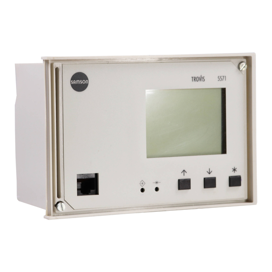
- Page 1 Automation System TROVIS 5500 Programmable Logic Controller (PLC) TROVIS 5571 Mounting and Operating Instructions EB 5571 EN Firmware version 1.21 ® Electronics from SAMSON Edition March 2009...
- Page 2 Moreover, we do not guarantee that the buyer can use the product for an intended purpose. SAMSON rejects any liability for claims by the buyer, especially claims for compensation including lost profits or any other financial loss, except the damage was caused intentionally or by gross negligence.
-
Page 3: Table Of Contents
Contents Contents Page Operation ....... 4 Operating elements......4 1.1.1 Operating keys . -
Page 4: Operation
Operation Operation The programmable logic controller (PLC) is freely programmable. The controller is delivered without an executable application in the memory. The application must be developed sepa- ® rately for the desired purpose on a personal computer using ISaGRAF (programming as in IEC 61131-1) and then transferred to the controller. -
Page 5: Display
Operation Display The programmable logic controller has a plain text display. The display is automatically illuminated when entering or setting the controller. After connecting the controller to the power supply, “System is being initialized…“ appears briefly on the display. Should the display not be illuminated or the contrast is too strong/weak, you can adapt the dis- play illumination. -
Page 6: Adjusting The Contrast Of The Display
Operation Note! If no key is pressed for two minutes, the PLC returns to the normal display. The background illumination of the display is switched off automatically. Any settings that have not been confirmed are not saved and must be re-entered. 1.2.1 Adjusting the contrast of the display Activate the editing mode. -
Page 7: Displaying Data
Operation Displaying data The states of the inputs and outputs as well as information on the connected meter bus instru- ments can be retrieved in the information level. In addition, the analog and binary outputs can be changed (refer to section 3 on manual operation). The information level is divided into individual menu items: Analog inputs ·... -
Page 8: Setting The System Time
Operation Setting the system time The current time and date need to be set immediately after start-up and after a power failure lasting more than 24 hours. Set the system time in the settings level under the menu item “Date / time”. The Automatic sum- mer time function can also be activated or deactivated in this menu item. - Page 9 Operation Enter month. Confirm month entered. Display: Year ( YYYY ) blinks. Enter year. Confirm year entered. Display: Time ( HH ) blinks. Enter hour. Confirm hour entered. Display: Minutes ( MM ) blink. Enter minutes. Confirm minutes entered. Settings level Display: “Automatic summer time? __“...
-
Page 10: Start-Up
To enable simple and clear programming, ready-made func- tions and function blocks, e.g. for boiler systems, heat exchanger sequence control, ventilation systems, heating circuits or domestic hot water systems, are available from SAMSON. Parameters* Settings level / Range of values... -
Page 11: Changing Plc Settings
Start-up Note! ® In ISaGRAF , internal variables can be assigned (integer or bool) network addresses. The status or value of the internal variable is written to the associated holding or coil register and can be read or written over Modbus. Important! The PLC application must be reloaded after a cold start. - Page 12 Start-up Confirm the key code. Settings level Display: Settings level Date / time RS-232/Slave The menu item “Date / time“ is highlighted. RS-485/Master Select the menu item in which the settings are to be RS-232/Prog Meter bus changed, e.g. “RS-232/Slave“. Universal input type Activate the selected menu item.
-
Page 13: Configuring Universal Inputs
Start-up Configuring universal inputs There are 17 universal inputs, which may be used as binary inputs, analog inputs (0 to 10 V, 0/4 to 20 mA) or as sensor inputs. The hardware must be configured accordingly (sensor ini- tialization). Refer to page 38 for the resistance values of the PTC, Pt 100 and Pt 1000 sensors. You can also configure each universal input separately. - Page 14 Manual operation Select the type of universal input. The inputs are available in the following order: PT100↔PT1000, PT100↔PTC, NI2000, PT2000, PT500, 0 – 10V, BE, 1000 – 2000Ω, PT100, PT1000, NTC, PTC, NI1000, NI200, 4 – 20mA, 0 – 20mA Note! On selecting the universal input types PT100 ↔...
-
Page 15: Resetting To Default Values
Appendix If both temperatures are not the same: Correct the sensor temperature. Confirm corrected temperature. If another type of universal input is selected: Universal input type UE12=PT100↔PT1000 Confirm the universal input type. UE13=PT100↔PT1000 UE14=PT100↔PT1000 UE15=PT100↔PT1000 Returning to the settings level UE16=PT100↔PT1000 UE17=PT100↔PT1000 Select Back to return to the settings level. -
Page 16: Manual Operation
Manual operation Manual operation All outputs configured in manual operating mode. Refer to the wiring plan (–> section 7). Note! If the analog and binary output menus are activated without entering the key code before- hand, the key icon appears at the top of the display when you press the enter key to con- firm the setting. -
Page 17: Operational Faults
Operational faults Analog output setting: 0 to 10 V Increase the value. Reduce the value. Setting with binary outputs: on/off Binary input = on Binary input = off Exit the output. Display: indicates manual intervention. Exiting the information level Information level Analog inputs Select Back to return. -
Page 18: Communication
(1400-7139). – Operation on a four-wire bus To link the controller and the bus line, the signal level needs to be converted by an appropriate converter (SAMSON cable converter 1400-7308). Fig. 1 · Network structure EB 5571 EN... - Page 19 Communication GND TD DTR Fig. 2 · Pin assignment, RJ-12 system bus interface Modbus slave interface RS-232 The Modbus connection is located on the rear panel of the controller housing (RJ 12 jack). The controller can be connected either directly to the serial interface of a PC (point-to-point connec- tion) or to a (dial-up) modem.
-
Page 20: Modbus Master Interface
Communication Modbus slave interface in combination with RS-232/RS-485 cable converters (for four-wire bus) Operating the PLC in combination with cable converters requires a permanent bus connec- tion (data cable). The bus line links the devices/control units in an open ring. At the end of the bus line, the data cable is connected to the control station using an RS-485/RS-232 con- verter (e.g. -
Page 21: Description Of Communication Parameters To Be Adjusted
Communication Parameters* Settings level / Range of values Gateway RS-485/Master / On, Off Addressing 8 bit RS-485/Master / 8-bit, 16-bit Baud rate 9600 RS-485/Master / 9600, 19200 Frame RS-485/Master / On, Off Bias voltage RS-485/Master / On, Off Validity 600 s RS-485/Master / 0 to 600 s Pause 0 ms... - Page 22 Communication Modem Modem = On: PLC connected to telecommunications network over a modem (RS-232 Modbus slave in- terface) Modem = Off: PLC directly connected to a computer (RS-232 Modbus slave interface) and on operating the PLC in combination with cable converters (RS-232/RS-485) Cyclical initialization This parameter defines the period of time for a cyclical issue of the initialization command “ATZ“.
-
Page 23: Meter Bus Interface
Communication Validity The values saved in the PLC, which have been sent by the slaves, have a time-dependent Validity . If the building control station polls the saved data within the valid period of time, the PLC sends the saved data directly to the building control station. However, if the polling to the PLC is outside of this valid time period, the PLC first polls the slaves and then sends these updated data to the building control station. - Page 24 Communication All settings that are made for communication with heat or Meter bus water meters are stored in Settings level > Meter bus > WMZ#1: EN1434/Cont. 250 WMZ#_. WMZ#2: None Set the parameters in the following sequence: WMZ#3: None – Model code –...
-
Page 25: Data Logging Module
Communication ID no. WMZ#1 (EN1434) Flow rate [l/h] ID no.: FFFFFFFF Flow rate: _.___ l/h Total capacity [m Total capacity: –.––– m3 Capacity [kW] Capacity: –.––– kW Energy [Mwh] Energy: –.––– Mwh Flow pipe [°C] Flow pipe: – °C Return flow pipe [°C] Back Meter bus address Status... -
Page 26: Saving And Loading Firmware And Applications
Communication Note! The Data logging function causes all the data previously saved in the module to be deleted. The data logging viewer software allows the data to be viewed in graph format. The USB-Con- verter 3 (order no. 1400-9377) is required to connect the data logging module to a computer. The data logging viewer software is supplied with the USB-Converter 3. -
Page 27: Installation
Installation Installation The controller consists of the housing with the electronics and the back panel with the terminals. It is suitable for panel, wall, and top hat rail mounting (Fig. 3). Panel mounting 1. Remove both screws (1). 2. Pull apart the controller housing and back panel. 3. - Page 28 Installation Panel mounting Back panel of the controller Controller housing Wall mounting Top hat rail mounting Dimensions in mm W x H x D = 144 x 96 x 111 Fig. 3 · Installation EB 5571 EN...
-
Page 29: Electrical Connection
Surge diverters must be installed at the control cabinet inlet. Noise suppression The TROVIS 5571 Controller with SAMSON actuator is interference suppressed according to VDE 0875. If different actuator makes are used, or moreover, further actuators with interfer- ence sources are used in a plant, the operator/supplier of a custom-made plant must make sure that the entire plant complies with VDE 0875 regulations due to the legal obligation of ensuring interference suppression. - Page 30 Electrical connection EB 5571 EN...
- Page 31 Electrical connection Connecting the PLC Open the housing to connect the cables. Make holes in the marked locations at the top, bottom or back of the housing’s back panel and fit suitable grommets or screw joints. Observe the diagram (Fig. 4) for connection. The connection diagram contains all possible in- puts and outputs.
-
Page 32: Appendix
Appendix Appendix Settings level Menu item Functions/parameters Setting range section Date/time System time (date and time) freely configurable Automatic summer time On / Off RS-232/Slave Modbus slave Station address 1 to 247, 255 16-bit addressing Yes / No Control system 1 to 300 min 30 min monitoring... - Page 33 Appendix Menu item Functions/parameters Setting range section Meter bus WMZ#1 to WMZ#3 Model code None, P15, PS2, EN1434, None CAL3, APAto, SLS Reading mode Coil, Cont, 24h Meter bus address 0 to 255 1) 2) Universal input type UE01 to UE17 PT100↔PT1000 PT100↔...
-
Page 34: Technical Data
Appendix Technical data TROVIS 5571 Programmable Logic Controller (PLC) Universal inputs 17 universal inputs, separately configurable as: – Resistance input Pt 100/500/1000, Ni 200/1000/2000, PTC/NTC, 1–2 kΩ – Current input 0/4 to 20 mA (50 Ω parallel resistor) – Voltage input 0–10 V –... -
Page 35: Special Key Codes
Note! The expansion module 1400-9386 (power supply 24 V AC) can be used in conjunction with TROVIS 5571 PLC (power supply 230 V AC) or with TROVIS 5572 Room Controllers (power supply 24 V AC). A 230 V AC/24 V AC transformer is required for the expansion module when it is used in... -
Page 36: Terminal Assignment
Or 0 to 10 V output 0 to 10 V input GND input/output 5/6 RS-485/MODBUS (slave) Connection to TROVIS 5571/5572 RS-485/MODBUS (master) Connection to expansion module(s) Only with smart expansion module, functioning similar to a basis device EB 5571 EN... -
Page 37: Integrating The Expansion Modules
Appendix 8.4.3 Integrating the expansion modules A maximum of four expansion modules (1400-9386) can be integrated over the Modbus mas- ter interface (Fig. 5) TROVIS 5571 Module 1 Module 2 Module 3 Module 4 Terminals RS-485 RS-485 RS-485 RS-485 RS-485 RS-485 RS-232 TROVIS... -
Page 38: Sensor Resistance Tables
Appendix Sensor resistance tables Resistance values with PTC resistors Type 5224 Outdoor Temperature Sensors, Types 5264 and 5265 Flow and Return Flow Tem- perature Sensors, Type 5264 Storage Tank Temperature Sensors –20 –10 °C Ω 694 757 825 896 971 1010 1050 1132 1219 1309 1402 1500 1601 1706 1815 1925 Resistance values with Pt 1000 resistors Type 5227-2 Outdoor Temperature Sensors, Type 5277-2 (thermowell required) and Type 5267-2 (contact sensor) Flow, Return Flow and Storage Tank Temperature Sensors. -
Page 39: Customer Data
Appendix Customer data Station Operator Relevant SAMSON office Settings Functions/parameters Setting range Setting Date/time System time (date and time) freely configurable Automatic summer time On/Off RS-232/slave Station address 1 to 247, 255 16-bit addressing Yes/No Control system 1 to 300 min... - Page 40 Appendix Meter bus WMZ#1 WMZ#2 WMZ#3 Model code None, P15, PS2, EN1434, CAL3, APAto, SLS Reading mode Coil, cont, 24h Meter bus address 0 to 255 Universal input UE 9 10 11 12 13 14 15 16 17 PT100↔PT1000 PT100↔PTC NI2000 PT2000 PT500...
- Page 41 Index Index 16-bit addressing....22 8-bit addressing....22 Firmware version .
- Page 42 Index Operating elements ....4 Sensor resistance values ... . . 39 Operational faults ....18 Sequential Function Chart .
- Page 43 EB 5571 EN...
- Page 44 RS-232/Slave RS-485/Master RS-232/Prog Meter bus Universal input type Back Back Normal display (depending on application) SAMSON AG · MESS- UND REGELTECHNIK Weismüllerstraße 3 · 60314 Frankfurt am Main Telefon: 069 4009-0 · Telefax: 069 4009-1507 EB 5571 EN Internet: http://www.samson.de...