Lennox iComfort S30 Installation And Setup Manual
Ultra smart thermostat
Hide thumbs
Also See for iComfort S30:
- Installation and setup manual (100 pages) ,
- User manual (20 pages) ,
- User manual (16 pages)

Related Manuals for Lennox iComfort S30


Summary of Contents for Lennox iComfort S30
- Page 1 ® Ultra Smart Thermostat 507536-05 5/2018 Installation and Setup Guide Supersedes 507536-04 2018 Lennox Industries Inc. © Dallas, Texas, USA...
-
Page 2: Table Of Contents
Service ....................16 Conventional Heat Pump Unit (Dual-Fuel) ........... 44 Alternative Method ................17 Partial iComfort System — iComfort Air Handler and Lennox Conventional Air Conditioner ..............44 Multiple Smart Hubs ................17 Partial iComfort System — iComfort Air Handler and Lennox Restarting Smart Hub ................ -
Page 3: Shipping And Packing List
Quantity Description iComfort S30 ultra smart thermostat includes a Smart Hub, HD Display, Mag- Mount and optional use wall plate. Before beginning installation, note the type of equipment, number of stages, and any accessories being installed. -
Page 4: External Components
• Do not install the Smart Hub on or near large metal objects. This could 3. For low voltage wiring connections use diagrams in section titled “Connecting Low Voltage Wiring” on page 8. adversely affect the range and directional coverage of the Smart Hub Wi-Fi signal. -
Page 5: Led Indicators
The push button has a LED associated with it that indicates the status of the Table 2. Terminal Designations Smart Hub commissioning state (see “Table 1. LED Indicators”). Terminal Designation Description Terminal Color lED I nDICators Communications bus B Green * ACC1 and ACC2 are for future use. -
Page 6: Led Indicators
Use either the Mag-Mount or wall plate as a template to mark the desired mounting hole locations Seal wire hole in wall to prevent on the wall. cold or hot air from affecting temperature sensor in display. IMPORTANT 9. Drill 3/16” (5 mm) holes at marked locations on the wall for anchors. Then insert wall anchors into holes until flush with the wall. -
Page 7: Hd Display Components And Installation
HD Display Components and Installation Smart Hub nstallatIon 1. Hold the HD Display by the edges, line it up with the Mag-Mount (horizontal position), and move the HD Display toward the Mag-Mount. System Status LED 2. When the magnets in the Mag-Mount attract the HD Display, guide it toward the Mag-Mount and let the magnets pull it into place. -
Page 8: External Components
Proximity Sensor The optional outdoor air (temperature) sensor (OAS) (X2658) wiring distance microSD Slot to the iComfort S30 should not exceed 150 feet (45 meters) when wired with minimum 22 #AWG (recommend 18 #AWG) dedicated 2-conductor thermostat Micro USB Connector cable. - Page 9 Outdoor Unit Indoor Unit Controller Smart Hub Mag-Mount 12VDC COM BUS R i+ I- C Single wire 12VDC Single wire COM BUS to bundle to indoor unit wire to indoor terminal “C”. Single wire terminal “C”. to terminal “C”. Unused wires Unused wires Unused wires Figure 4.
-
Page 10: Wiring Diagrams
IrIng Iagrams The following diagrams are typical low voltage wiring connections for various DATS (Optional) system configurations. OATS (Optional) SETUP NOTE: CUT Y1-Y2 ON-BOARD LINK FOR DATS (Optional) 2-STAGE OUTDOOR UNITS (NON-COMMUNICATING) OATS (Optional) 24VAC Outdoor Unit (1 - or 2-Stage Air Conditioner) S30 Smart-Hub Mag-Mount iComfort Indoor Unit... - Page 11 DOOR” ON DAMPER CONTROL MODULE TO CONNECT TO THE INDOOR UNIT. OATS (Optional) IHARMONY ZONING S30 Smart Hub SYSTEM DATS (Required) IN-ZONE Mag-Mount THERMOSTATS iComfort iComfort Indoor Outdoor Unit Unit UP TO THREE IN-ZONE To iHarmony THERMOSTATS ARE SUPPORTED To indoor unit To Smart If unable to connect two wires See iHarmony Installation instruction for damper connection information.
- Page 12 AUXILIARY DEHUMIDIFIER MODELS HCWHD3-070 AND HCWHD-095 AUXILIARY DEHUMIDIFIER MODELS HCWHD-090 AND HCWHD-135 NOTE: HCWHD-065 IS NOT COMPATIBLE SPDT RELAY S30 SMART ICOMFORT INDOOR S30 SMART S30 MAG UNIT MOUNT ICOMFORT INDOOR AUXILIARY UNIT DEHUMIDIFIER S30 MAG MOUNT Figure 11. iComfort System with Auxiliary Dehumidifier Accessory...
- Page 13 SLP98 & G71MPP FURNACE (IFC) OR AIR HANDLER (AHC) FOR SL280 & EL296, SEE HUMIDIFIER DIAGRAM BELOW NOTE: 24V UV LIGHT APPLICATIONS (BOTTOM RIGHT) ® IN AN ICOMFORT SYSTEM, NEITHER FURNACE NOR AIR HANDLER CHARGE AIR SENSOR (SEE DAS NOTES) CATIONS.
- Page 14 SLP98 & G71MPP FURNACE (IFC) OR AIR HANDLER (AHC) LVCS VENTILATION CONTROL SMART HUB SYSTEM Mag-Mount 26L56 CURRENT SENSING RELAY KIT. NOTE: PASS THE BLOWER MOTOR L1 WIRE THROUGH THE RENT SENSING RELAY AS SHOWN. HVAC HEAT OR COOL CALL, OR THE FAN IS IN CONTINUOUS OPERATION, THE VENTILATION CONTROLLER WILL OPEN OA DAMPER TO VENTILATE IF THE OUTDOOR TEMPERATURE AND TION CONTROLLER.
-
Page 15: Electric Heat Configuration For Icomfort Air Handlers
HEAT HUMIDITROL 1 2 3 4 XFMR 24V COOL HUMIDIFICATION This application tool is used by dealers to commission a iComfort S30 ultra 24 VAC smart thermostat using a Wi-Fi enabled mobile device. 1 2 3 4 SMART AUTO EVENHEAT... -
Page 16: Establishing A Direct Wireless Connection To The Smart Hub
13. Once disconnected, the Smart Hub commissioning LED will change to staBlIshIng a IrECt IrElEss onnECtIon to thE mart solid blue. IMPORTANT 14. Reinstall the HD Display on the Mag-Mount. ErvICE If the connection between the iComfort Mobile Setup application and Smart Hub is idle for three (3) minutes, the Smart Hub will auto-disconnect from the To use iComfort Mobile Setup application as a service tool, the commissioning mobile device. -
Page 17: Alternative Method
If problem persists, please contact your iComfort dealer at 1-800-555-8888 EstartIng mart For additional support, contact Lennox at Pressing the Smart Hub button for more than five seconds will reboot the Smart 1-800-9-LENNOX or visit www.lennox.com/support Hub. Figure 16. Communication Error Message Example... -
Page 18: Apple Homekit Wi-Fi Accessory Configuration
EIM-Furnace or EIM-Air Handler. When using a EIM the outdoor unit may be either a Lennox iComfort or any standard 24VAC non-communicating unit. NOTE: Not all equipment may be visible from the equipment found system screen. -
Page 19: Reminders
1. Touch on the circled green arrow to touch a specific zone. The that zone EmInDErs settings will expand to allow the installer to adjust CFMs for each circulation This screen allows you to set reminders as either disabled or 3, 6, 12 or 24 airflow type. -
Page 20: Dealer Control Center
To navigate back to the dealer control center, < Use to run test on Use to run touch on the Dave Lennox icon when available system components diagnostics on on the top left-hand side of the screen. system components <... -
Page 21: Equipment Parameters
The following is a complete list of all possible parameters listed under System. Parameters actually available are dependent on the Lennox communicating equipment type detected and non-communicating equipment added. - Page 22 Outdoor Units Only) Default is 3.0. Range is 1.0 to 15.0 in increments of 0.5. This parameter is only available when a Lennox modulating outdoor units is installed along with a discharge air temperature sensor (DATS) Installed is used. DAT Offset Default is 0.0°F (0.0°C).
- Page 23 When the system is dual-fuel and steady state while operating at full HP demand, this is the amount of °F (°C) below the set point that is allowed before allowing to switch Difference to gas heat. (Lennox Modulating Range is 0.5 to 10°F (0.0 to -5.56°C). Default is 1.5°F (1.30°C). Adjustments are in increments of 0.5°F (0.14°C). Heat Pumps) Heat Cool Stages Locked In Heat Cool (H/C) Stages Lock in default is disabled (heat/cool stages are turned off separately).
- Page 24 Table 4. Smart Hub Parameters Parameter Description Heating - Heat Pump with Electric - 3 Stage (2 compressor / 1 backup OR 1 compressor / 2 backup) 1st stage Stages Stg1 Differential Locked = 2nd stage stage Stg2 Differential 3rd stage 3rd stage Stg3 Differential 1st stage...
- Page 25 Table 4. Smart Hub Parameters Parameter Description Heating - Dual Fuel - 3 Stage (1 compressor / 2 backup) 1st stage Stages Stg1 Differential Locked = Disabled 2nd stage Stg2 Differential 3rd stage stage Stg3 Differential 1st stage Stages Stg1 Differential Locked = 2nd stage Enabled...
- Page 26 60 – 70 percent range and/or adjust comfort mode CFM. • Normal is when the heat pump will heat the home will providing the highest efficiency. (Lennox Modulating Heat Pumps Only) • Comfort is when the heat pump will deliver warmer air for comfort, but sacrifices on efficiency.
- Page 27 Step change gains deal with set point changes and affects how fast the system reaches the next set point. Change PI Gain Options are less aggressive, standard and more aggressive. Default is standard. (Lennox Modulating Outdoor Units) Modulating Cooling Steady Steady state gain controls the demand when the system is not responding to a sensed temperature change away from the iComfort thermostat setting.
- Page 28 Conservative - The system will wait longer to display any Smart Alert Enable alarms. This options allow for a minimum chance for false alarms being shown. • Medium (default) - Extensive testing by the Lennox development team to minimize the number of false alarms. •...
- Page 29 Differentials NOTE: Lennox variable capacity systems will stage electric heat but not on differentials. It will use the thermostat PI logic to stage the electric heat. If the system has a (1 through 6) variable capacity furnace or zoning all stage differentials will be ignored.
- Page 30 Differential NOTE: For Lennox Modulating Outdoor Units differentials are ignored. Minimum and maximum CFM will be dependent on system component configurations. These parameter values are automatically adjusted to the specific hardware config- uration. See iHarmony zoning system installation instruction for minimum CFMs for specific indoor units.
- Page 31 Dehumidification Airflow Adjustment Adder in percentage. Adjustment Adder Both these values are in the installer set up under dealer control center > equipment > heat pump. Range is 0 to 30%. Default is 28%. (Lennox Modulating Heat Pumps Only) NOTE:...
- Page 32 Dehumidification Airflow Adjustment Adder in percentage. Both these values are in the installer set up under System Device/Air Conditioner/High Normal Cooling Adjustment Adder Airflow). (Lennox Modulating Air Conditioners Only) NOTE: Deactivated in auxiliary dehumidification and Enhanced Dehumidification Accessory (Humiditrol).
- Page 33 Table 7. Air Handler Parameters Parameter Description Provides information concerning unit code, language support, equipment type name, unit model number, unit serial number, unit nominal capacity, number of heating states, heating capacity by stage, indoor blower CFM range, control software revision, control model number, control serial number, control hardware revision, discharge About air temp sensor, outdoor air temp sensor, protocol revision number, device product level, factory installed transformer, 24VAC average power consumption, 24VAC peak power consumption, line voltage average power consumption, line voltage peak power consumption, compatible devices list, applicable code memory size, and...
- Page 34 Table 8. Furnace Parameters Parameter Description This screen provides information on unit code, language supported, equipment type name, unit model number, unit serial number, unit nominal capacity, number of heating stages, heating capacity by stage, indoor blower CFM range, control software revision, control model number, control serial number, control hardware revision, About discharge air temp sensor, outdoor air temp sensor, protocol revision number, device product level, factory installed transformer, 24VAC average power consumption, 24VAC peak power consumption, line voltage average power consumption, line voltage peak power consumption, compatible devices list, application code memory size...
- Page 35 Table 8. Furnace Parameters Parameter Description HP Indoor Blower The range is 0.0 - 30.0 seconds with a default setting base on equipment type match-up. Adjustment are increments of 5 seconds. Default is 0.0 seconds. On Delay Range of operation of the indoor blower during low cooling operation. Low Cooling Airflow The range is dependent of indoor unit model and size.
- Page 36 Table 9. Zoning Control Parameters Parameter Description This provides information on unit code, language supported, equipment type name, control software revision, control model number, control serial number, control hard- ware revision, protocol revision number, device product level, 24VAC average power consumption, 24VAC peak power consumption, compatible devices list, application About code memory size, micro-controller part number, max number of zones, supported damper types, number of damper positions, zone temp sensor 1, zone temp sensor 2, zone temp sensor 3 and zone temp sensor 4.
- Page 37 Table 12. PureAir S Parameters Parameter Description Equipment PureAir Filter Default: ON. Options are either ON or OFF. This parameter turns on and off the filter life and UV lamp life reporting. When set to off, the control will continue to calculate the remaining filter life through continu- ous sampling, but will not use filter tests to determine filter life.
-
Page 38: Tests
Adding dealer information will ensure the thermostat is associated with your These screens allow for verification and modification of CFMs for blower, LennoxPros account when connecting to the Lennox server. heating and cooling circulation. Touch continue to proceed to the next screen. -
Page 39: Dehumidification Settings
Home Address On this screen general information needs to be verified or changed. Touch any line item to change its contents. Information to be added is address 1, address 2, state, city and zip/postal code. Complete the requested information and press the continue button. Dehumidification Settings For firmware version 3.15 and later, all controls for dehumidification are listed at menu >... - Page 40 Table 15. Dehumidification Control Modes of Operations Mode of Option Description Operation Both Staged and Modulating Outdoor Units: Dehumidifies while servicing a cooling demand and will not over cool. The overcooling slider is hidden from the user. Normal Modulating units use the “comfort” table to run the system, regardless of the presence of a discharge air temperature sensor (DATS). Staged Outdoor Unit: If at the start or during a cooling call, the humidity is above the relative humidity set point then the unit dehumidifies during the cooling demand.
-
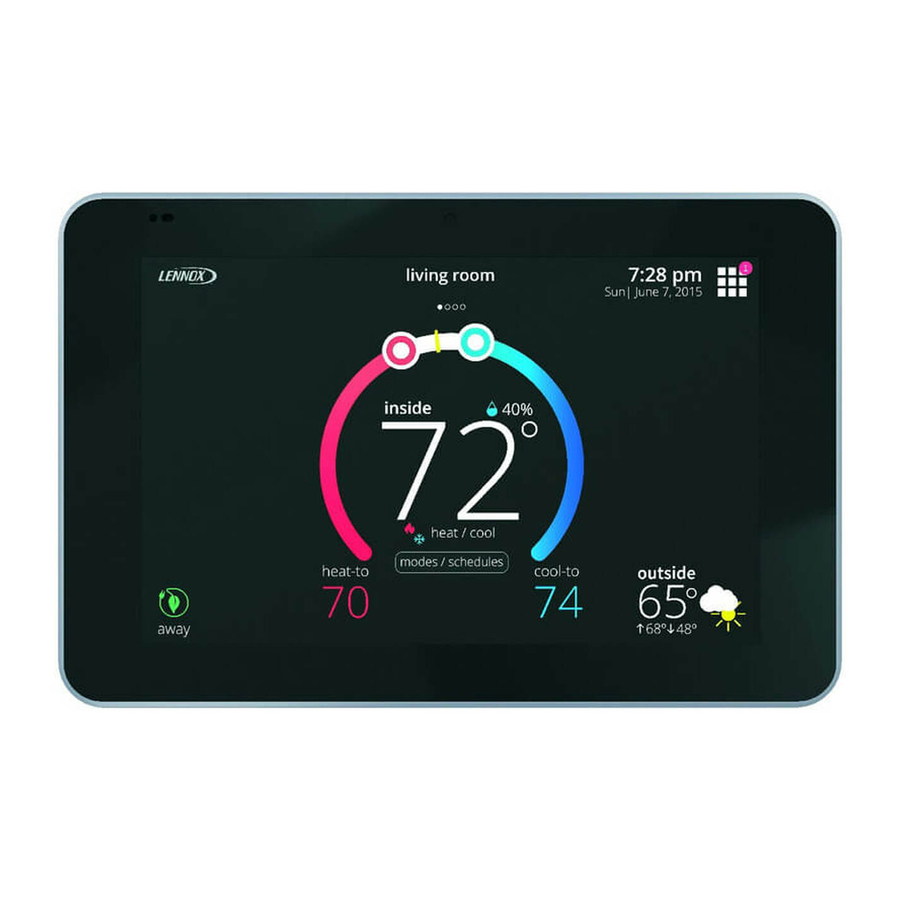
Page 41: Displaying Outdoor Temperature (Sensor) And Indoor Humidity On The Home Screen
Displaying Outdoor Temperature (Sensor) and Indoor Humidity on the System Configurations Home Screen — F omplEtE I omFort ystEms urnaCE anD onDItIonEr IsplayIng thE utDoor Ensor EmpEraturE on thE CrEEn An iComfort gas furnace (G71MPP, EL296V, SLP98 or SL280) with an iComfort An outdoor temperature sensor is provided in all iComfort outdoor units. -
Page 42: (Dual-Fuel)
— F hp u — a omplEtE I omFort ystEms urnaCE anD omplEtE I omFort ystEms anDlEr anD onDItIonEr An iComfort air handler (CBX32MV or CBX40UHV) with an iComfort air An iComfort gas furnace (G71MPP, EL296V, SLP98 or SL280) with an iComfort conditioner (SL18XC, XC17, XC20, XC21 or XC25). -
Page 43: Complete Icomfort Systems - Air Handler And Heat Pump Unit
2. Cut option link 2-stage compr (Y1 to Y2, W915) on furnace control on two- check the system for installed communication devices. stage Lennox brand conventional air conditioner units only. 5. During commissioning you will end that process with the dealer control 3. -
Page 44: Partial Icomfort System - Icomfort Furnace And Lennox Conventional Heat Pump Unit (Dual-Fuel)
(R, i+, i-, C). the screen to return to the dealer control center. • iComfort air handler to conventional Lennox brand air conditioner (5 – 14. Touch exit to return to the home screen. 8 wires). (Y1, Y2, C, R, W1,W2). -
Page 45: Partial Icomfort System - Icomfort Air Handler And Lennox Conventional Heat Pump Unit
12. Here you will have another opportunity to adjust blower circulation, heating • When matched with conventional Lennox brand 2-stage heat pump, and cooling circulation air flows. Use the plus or minus buttons to adjust cut the Y1-Y2 2-stage comp on-board clippable link. -
Page 46: G71Mpp Or Slp98 Furnace Setting Adjustments
• Up to 8-conductor thermostat wire from the non-communicating Wi-Fi Connection furnace terminal strip to the equipment interface module (R, C, O, Y1, Y2, G, W1, W2 and W3). This is for connecting the thermostat to a secure home wireless network. •... -
Page 47: Performance Reports
6. Once security type is selected, a password field will appear. Enter the To eliminate a possible source of interference, temporally disable any devices password to access your home Wi-Fi network. and see if Wi-Fi performance has improved. Received Signal Strength Indication (RSSI) NOTE: If you wish to see the characters you are typing, check show password. -
Page 48: Replacement Parts
• Minor and Moderate alerts are found only in the Installer alert button. What does minor and moderate mean? • Minor is information only, helps Lennox interpret test results, understand complicated behavior. • Moderate means that the system will likely recover on its own, no action necessary. -
Page 49: Soft Disable
Initial notification of critical alerts will pop up on the home screen and will be listed under notification menu. Minor and moderate alerts are found only under the notification menu. * Current Lennox modulating outdoor units are XC20, XP20, XC25 and XP25. - Page 50 Initial notification of critical alerts will pop up on the home screen and will be listed under notification menu. Minor and moderate alerts are found only under the notification menu. * Current Lennox modulating outdoor units are XC20, XP20, XC25 and XP25.
- Page 51 Initial notification of critical alerts will pop up on the home screen and will be listed under notification menu. Minor and moderate alerts are found only under the notification menu. * Current Lennox modulating outdoor units are XC20, XP20, XC25 and XP25.
- Page 52 Initial notification of critical alerts will pop up on the home screen and will be listed under notification menu. Minor and moderate alerts are found only under the notification menu. * Current Lennox modulating outdoor units are XC20, XP20, XC25 and XP25.
- Page 53 Initial notification of critical alerts will pop up on the home screen and will be listed under notification menu. Minor and moderate alerts are found only under the notification menu. * Current Lennox modulating outdoor units are XC20, XP20, XC25 and XP25.
- Page 54 Initial notification of critical alerts will pop up on the home screen and will be listed under notification menu. Minor and moderate alerts are found only under the notification menu. * Current Lennox modulating outdoor units are XC20, XP20, XC25 and XP25.
- Page 55 Initial notification of critical alerts will pop up on the home screen and will be listed under notification menu. Minor and moderate alerts are found only under the notification menu. * Current Lennox modulating outdoor units are XC20, XP20, XC25 and XP25.
- Page 56 Initial notification of critical alerts will pop up on the home screen and will be listed under notification menu. Minor and moderate alerts are found only under the notification menu. * Current Lennox modulating outdoor units are XC20, XP20, XC25 and XP25.
- Page 57 Initial notification of critical alerts will pop up on the home screen and will be listed under notification menu. Minor and moderate alerts are found only under the notification menu. * Current Lennox modulating outdoor units are XC20, XP20, XC25 and XP25.
- Page 58 Initial notification of critical alerts will pop up on the home screen and will be listed under notification menu. Minor and moderate alerts are found only under the notification menu. * Current Lennox modulating outdoor units are XC20, XP20, XC25 and XP25.
- Page 59 Initial notification of critical alerts will pop up on the home screen and will be listed under notification menu. Minor and moderate alerts are found only under the notification menu. * Current Lennox modulating outdoor units are XC20, XP20, XC25 and XP25.
- Page 60 Initial notification of critical alerts will pop up on the home screen and will be listed under notification menu. Minor and moderate alerts are found only under the notification menu. * Current Lennox modulating outdoor units are XC20, XP20, XC25 and XP25.
- Page 61 Initial notification of critical alerts will pop up on the home screen and will be listed under notification menu. Minor and moderate alerts are found only under the notification menu. * Current Lennox modulating outdoor units are XC20, XP20, XC25 and XP25.
- Page 62 Critical Furnace on DS terminal for a minimum • Dealer has cut the W914 jumper (Dehum, Harmony III) on the Lennox Furnace Control. Open of 10 seconds or on a power • The thermostat monitors the DS terminal in the furnace for power and if the link has been cut reset.
- Page 63 Initial notification of critical alerts will pop up on the home screen and will be listed under notification menu. Minor and moderate alerts are found only under the notification menu. * Current Lennox modulating outdoor units are XC20, XP20, XC25 and XP25.
- Page 64 Initial notification of critical alerts will pop up on the home screen and will be listed under notification menu. Minor and moderate alerts are found only under the notification menu. * Current Lennox modulating outdoor units are XC20, XP20, XC25 and XP25.
- Page 65 Initial notification of critical alerts will pop up on the home screen and will be listed under notification menu. Minor and moderate alerts are found only under the notification menu. * Current Lennox modulating outdoor units are XC20, XP20, XC25 and XP25.
- Page 66 Initial notification of critical alerts will pop up on the home screen and will be listed under notification menu. Minor and moderate alerts are found only under the notification menu. * Current Lennox modulating outdoor units are XC20, XP20, XC25 and XP25.
- Page 67 Initial notification of critical alerts will pop up on the home screen and will be listed under notification menu. Minor and moderate alerts are found only under the notification menu. * Current Lennox modulating outdoor units are XC20, XP20, XC25 and XP25.
- Page 68 Initial notification of critical alerts will pop up on the home screen and will be listed under notification menu. Minor and moderate alerts are found only under the notification menu. * Current Lennox modulating outdoor units are XC20, XP20, XC25 and XP25.
- Page 69 Initial notification of critical alerts will pop up on the home screen and will be listed under notification menu. Minor and moderate alerts are found only under the notification menu. * Current Lennox modulating outdoor units are XC20, XP20, XC25 and XP25.
- Page 70 Initial notification of critical alerts will pop up on the home screen and will be listed under notification menu. Minor and moderate alerts are found only under the notification menu. * Current Lennox modulating outdoor units are XC20, XP20, XC25 and XP25.
- Page 71 Initial notification of critical alerts will pop up on the home screen and will be listed under notification menu. Minor and moderate alerts are found only under the notification menu. * Current Lennox modulating outdoor units are XC20, XP20, XC25 and XP25.
- Page 72 Initial notification of critical alerts will pop up on the home screen and will be listed under notification menu. Minor and moderate alerts are found only under the notification menu. * Current Lennox modulating outdoor units are XC20, XP20, XC25 and XP25.
- Page 73 Initial notification of critical alerts will pop up on the home screen and will be listed under notification menu. Minor and moderate alerts are found only under the notification menu. * Current Lennox modulating outdoor units are XC20, XP20, XC25 and XP25.
- Page 74 Initial notification of critical alerts will pop up on the home screen and will be listed under notification menu. Minor and moderate alerts are found only under the notification menu. * Current Lennox modulating outdoor units are XC20, XP20, XC25 and XP25.
-
Page 75: Installation Checklist
Can the homeowner access the consumer portal (www.myicomfort.com) from either a PC or tablet? Has the homeowner downloaded the Lennox Thermostat application from either Google Play or IOS App Store to their mobile devices? Is the Lennox Dealer account number or your main shop phone number been added to the dealer information screen? If applicable, has the air handler’s electric heat strips been commissioned? If not, commissioning of heat strips must be performed. -
Page 76: Electrical Troubleshooting
Gas Furnace (IFC) 2.84 2.615 applicable expected voltages. Applicable controls are thermostats, Lennox Air Handlers - CBX32MV 2.44 iComfort Equipment Interface Module (EIM) and iHarmony (DCM) and all and CBX40UHV (AHC) iComfort Air Handler, Furnaces and Outdoor Units. -
Page 78: Index
Index Dehumidification Smart Hub 37 Thermostat 37 Airflow % 34 Advanced Dehumidification Descriptions 39 Airflow Adjustment Adder 31, 32 Fan Cycling 32 Airflow Profile - Cooling 33, 34 Set Point 39 Freezing Alert Temperature 28 Alert Codes and Troubleshooting 49 Setting Options 39 Apple HomeKit 18 Dew Point Adjustment 22... - Page 79 Information 38 HP Heating Steady State PI Gain 27 Group ID 26 HP Heating Step Change PI Gain 27 Installation 3 Installation LEDs 5 Checklist 75 Multiple Devices 17, 26 Recommendations 3 Number of Gas Heating Stages 27 Parameters 21 Report 38 Push Button 4 Restart 17, 37...
- Page 80 Zoning Anticipated Discharge Air Temperature Adjustment 30 Continuous Blower CFM 30 Gas Heating DAT Cool Down Target 30 Minimum Zone Run-Time 30 Supply Air Temp Limit for Cooling 30 Supply Air Temp Limit for Gas / Electric Heating 30 Target Supply Air Temp for Cooling 30 Target Supply Air Temp for HP Heating 30 Zoning Target Supply Air Temp for Gas/Electric Heating 30...