Lennox icomfort Wi-Fi Setup Manual
Icomfort wi-fi thermostat
Hide thumbs
Also See for icomfort Wi-Fi:
- Setup manual (84 pages) ,
- Installer's system setup manual (48 pages) ,
- Homeowner's manual (20 pages)
Table of Contents
Advertisement
E2012 Lennox Industries Inc.
Dallas, Texas, USA
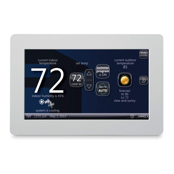
indoor temperature
set temp
75
72
indoor humidity is 41%
system is cooling
Wi−Fi
9:39 am Aug 15, 2012
THIS MANUAL MUST BE LEFT WITH THE HOMEOWNER
FOR FUTURE REFERENCE
NOTICE
Read this manual before programming this thermostat.
Use this thermostat only as described in this manual.
09/12
*2P0912*
outdoor
temperature
80
heat
or
cool
cool−to
fan is
AUTO
fan is
fan is
heat to
AUTO
OFF
INSTALLER'S SYSTEM SETUP
GUIDE
icomfort Wi-Fit Thermostat
Touch Screen Programmable Communicating Thermostat
CONTROLS
506920−01
away
mode
09/12
Supersedes 05/12
icomfortt−Enabled Units
G71MPP−03 or later
SLP98−01 or later
SL280−03 or later
EL296V−01 or later
CBX40UHV−02 or later
CBX32MV−06 or later
Shipping and Packing List
1 −
icomfort Wi-Fit thermostat
4 −
Mounting Screws
4 −
Wall Anchors
1 −
Installation Quick-Start Guide
1 −
Installer's System Setup Guide
1 −
Homeowner's Manual
1 −
Warranty card
XC17−02 or later
XP17−02 or later
XP19−06 or later
XC21−05 or later
XP21−01 or later
506920−01
*P506920-01*
Advertisement
Table of Contents
Troubleshooting

Related Manuals for Lennox icomfort Wi-Fi


Summary of Contents for Lennox icomfort Wi-Fi
- Page 1 INSTALLER’S SYSTEM SETUP GUIDE E2012 Lennox Industries Inc. icomfort Wi-Fit Thermostat Dallas, Texas, USA Touch Screen Programmable Communicating Thermostat CONTROLS 506920−01 away outdoor mode 09/12 indoor temperature set temp temperature Supersedes 05/12 heat cool cool−to icomfortt−Enabled Units fan is AUTO...
-
Page 2: Table Of Contents
Table 6. Troubleshooting Tips ........Table of Contents Page Wiring Diagrams... -
Page 3: Technical Description/Features
icomfort Wi-Fit Thermostat − Technical Description and Features The 24VAC icomfort Wi-Fit thermostat (figure 1) is an electronic communi- BEST PRACTICES! Keep all communication wiring as far away from house cating, color display touchscreen, 7−day programmable thermostat. It stores electrical wiring and large electrical appliances as possible (15’ [5m] recom- system parameters and settings in nonvolatile memory (i.e., it retains data mended). -
Page 4: Installation And Setup
Installation and Setup IMPORTANT! Make sure the router is capable of, and set to operate in System settings (figure 2) appear first. As you use the up/down arrows to scroll through the settings, the right hand side will show the current value. wireless network b"... -
Page 5: Change Settings (Dealer Info, Daylight Savings, Fan Circulate)
Change settings Circulate Fan ON Time Range up/down is 15 to 50 % arrows Default is 35, inc: 1 If you want to change a setting, use one of the Settings change tools shown set−to in figure 3. (Also, see Set time and date on Page 7.) After changes have been made, use save to store the changed data or cancel to exit the screen and return to the list of settings. -
Page 6: Circulate Fan On Time Setting
35% (21 minutes fan run time per hour) 45% (27 minutes fan run time per hour). Dealer Number **** Table 1 shows the range/condition and defaults for the system settings and Dealer Name Lennox indicates the tools used to make changes. Dealer Address (alpha−numeric use keyboard characters) -
Page 7: Set Time And Date
Set time and date Use the arrows to select Time and Date; press edit (see figure 5) to proceed When Time and Date" screen (figure 6) appears, enter the correct date as to the Set current time and date" screen (figure 6). follows: Use the left and right arrows to change the month and year. - Page 8 Use about" screen & access Add or Remove Non−communicating equipment" screen The about" screen shows details of discovered installed equipment. From the system devices" screen, use arrow buttons to scroll to a device; then press the about button. Use the up/down arrows to scroll through and view additional information about the selected device.
-
Page 9: Add Or Remove Non−Communicating Equipment
Add or Remove Non−communicating equipment Figure 7 (previous page) shows how to access the Add or Remove Non− HUMIDITY CONTROL TIPS communicating equipment" screen. The standard humidification mode is Basic" (humidifier is energized during a call for heat, if there is a humidification demand). Sensed outdoor temperature, required for some features, is provided Adding Non−Communicating Outdoor unit See figure 8 for details... -
Page 10: Outdoor Unit
Add Non−Communicating Outdoor unit To add (or remove) an outdoor unit that is not icomfortt−enabled, you must be at the Add or Remove Non−communicating equipment?" screen. 1. Press the yes button on this screen (see 1). Add or Remove System Devices 2. -
Page 11: Humidifier
Add (or Remove) Humidifier (skip if no humidifier is being used) NOTE − Adding humidity regulating non−communicating devices may be a 2−step procedure: Before adding a humidifier, be sure that: S the humidifier is wired to the furnace or air handler control as shown on the Optional 1st, the device must be installed (this page;... -
Page 12: Dehumidifier
® Add (or Remove) Humiditrol or Auxiliary Dehumidifier (skip if no dehumidifying device is being used) Before adding a dehumidifier, be sure that: NOTE − Adding humidity regulating non−communicating devices may be a 2−step procedure: S the dehumidifier is wired to the furnace or air handler control as shown on the Option- 1st, the device must be installed (this page;... -
Page 13: Adjust A Setting Screen
Adjust a setting screen (communicating devices) Use arrows to select a device from the system devices" list; then use the about button to view information (shown on Page 8) about communicating devices (information about other devices is not available). Use resetAll button to un−install all non−communicating devices that were added through Add or Remove..." screen and to reset any device settings made through this Adjust a setting..."... - Page 14 Use the up/down arrows to scroll through the device’s settings. The current setting will be displayed on the right−hand side of the screen (figure 12). For example, current value: disabled. Press edit if you want to modify that setting, or press back to return to the previous screen. Available settings for the devices depend on the installed components.
-
Page 15: Configure Humidifier
Adjust a setting... Configure Humidifier (skip if no humidifier is being used or if humidifier is being used and default Basic" humidification mode is desired) Pre−adjustment REQUIREMENTS: 1st, the device has been installed (see Page 11). System Devices To adjust a setting, highlight it, 2nd, you pressed next at the Add or Remove..."... -
Page 16: Configure Dehumidifier (Humiditrol®/Aux. Dehum. Installed)
® Adjust a setting... Configure Humiditrol or Auxiliary Dehumidifier Pre−adjustment REQUIREMENTS: To adjust a setting, system devices 1st, the device has been installed (see Page 12). highlight it, System about 2nd, from the Add or Remove Non−communicating equipment?", press next. then press Edit Air Conditioner 3rd, in the Adjust a setting..."... -
Page 17: Configure Dehumidification (No Dehumidifier Installed)
Adjust a setting... Configure Dehumidification (no dehumidifying device installed) (skip if default Basic" dehumidification mode is desired) Pre−adjustment REQUIREMENTS: System Devices To adjust a setting, highlight it, 1st, NO physical dehumidification device has been installed. then press Edit 2nd, configure the thermostat for dehumidification as follows: System 1. -
Page 18: Humidification And Dehumidification Modes How They Work
Humidification and Dehumidification Modes how they work HUMIDIFICATION modes In PRECISION mode, dehumidification occurs if all BASIC conditions are true, except cooling demand may or may not be present. Also note that: Maximum overcool from cooling setpoint is 2ºF. BASIC & PRECISION These modes allow user control of RH between 15 and 45%. -
Page 19: Use The Test Features
Use the Tests / Diagnostics features NOTE − Test mode lasts for 30 minutes (with the temperature updating every select tests to run 30 seconds) except for the defrost test, which lasts 30 seconds. Tests fea- Blower ture provides the technician time to manually verify the equipment operation. HP Heat −... -
Page 20: Set Up Equipment Parameters
After pressing next after the final test, the Testing finished" screen will ap- Set up Equipment parameters pear (figure 20). At this point, use the EXIT button (if you have completed the Press equipment to set up equipment parameters and edit details of de- required setup), or use diagnostics button (to analyze the system), or use vices in the system without having to re−run the setup program. -
Page 21: Use The Diagnostic Features
When finished, press back; equipment parameters screen (figure 21B re- setup tests equipment turns); then press next. Select tests to run screen appears" (Page 19); ei- ther run tests as before or press skip tests. system devices Low Heating Airflow The Testing process screen"... -
Page 22: View And Clear Alerts
Press done when finished with the information. Select another device to From the user’s home screen, press and hold the Lennox" logo in the bottom diagnose or use EXIT (to close and go to user Home screen) if finished. right corner of the thermostat to access the installer program. Press yes when asked if you want to proceed. - Page 23 setup tests equipment alerts diagnostics setup tests equipment System Devices system and device alerts System No Alerts Furnace Thermostat select all view active deselect all view cleared back 9:39 am Aug 15, 2012 EXIT 9:39 am Aug 15, 2012 Figure 25. Cleared alert confirmation setup tests equipment...
-
Page 24: Enable Wi−Fi From User Home Screen
Enable the thermostat’s Wi-Fi feature from the Home screen Secure Connection Recommended! network security key or passphrase press any line to edit it none Make sure the router is capable of, and set to operate in displays information here as keys pressed network name (SSID) wireless network b"... - Page 25 NOTE − Time from pushing the registration button on the thermostat and re- Registering the icomfort Wi-Fit thermostat ceiving the consumer portal register link from your email on your computer is from 5 to 15 minutes. From NETWORK SETTINGS screen, you can change to the desired net- After registration has been completed, any available firmware downloads work as shown in figure 28.
-
Page 26: Register The Icomfort Wi-Fit Thermostat
Lennox icomfort system. Registering your thermostat will allow you to remotely access it from anywhere in the world on any device with an internet connection. Please com- plete your Lennox icomfort registration by clicking the link be- low: Register NOTE −... -
Page 27: Pc Welcome Screen, Interactive Demo, Gelaskins
Personal Computer Welcome page; Interactive Demo; Online icomfort information; Using Gelaskins Welcome home. ® Access all the great Wi−Fi enabled features on your icomfort thermostat from our secure web portal. After signing in, you´ll be able to view your icom- fort system settings, adjust the temperature and view reminders and alerts ˘... -
Page 28: Access Installer Program From User Home Screen
To access the installer program after the unit has been placed in operation A message screen stating Qualified Lennox equipment installer warning" and the user home screen is displayed, press the Lennox" logo and hold for screen appears (Figure 33). Press yes to proceed (no returns to the home 5 seconds (see figure 32). -
Page 29: Reconfigure A System
To begin reconfi- will change to the system discovery screen. At this point, the program goes guring a system (after you have accessed the program from the Lennox logo through the same setup as the initial setup process which begins on [previous page]), press the setup button (1, figure 34A). -
Page 30: Stage Delay Timers & Differentials
Stage Delay & Differential Settings (Installer settings) 1st Stage Differential1 Stage 1 differential is used in all thermostats. The previous stage of heating or cooling will not raise or lower the room tempera- default is 1.0°F but can be programmed between 0.5° and 3.0°F in 0.5°F in- ture to the setpoint in a given time. -
Page 31: Smooth Setback Recovery (Ssr)
Smooth Setback Recovery (SSR) SSR is an algorithm designed to smoothly" reach a occupied program Rules for SSR: schedule setpoint. The algorithm looks 2 hours ahead for the occupied pro- 1. SSR is enabled when Smooth Setback Recovery" is set to enabled gram schedule period’s setpoint. -
Page 32: Heat Pump, Dual Fuel And Balance Points
Heat Pump, Dual Fuel and Balance Points IMPORTANT − The Balance Points feature requires that a sensed out- pump is not as effective at a lower outdoor temperatures, it may be more door temperature is provided to the thermostat. This can be either a comfortable to use the auxiliary electric heat or the furnace (in dual fuel sys- tems, it may be more economical) to satisfy a demand for heat. - Page 33 Shut down HP Abbreviations: Stg 1...Stg 2 FURN = auxiliary heat provided by gas furnace HP = compressor heat T’stat LBP = Low Balance Point heat HBP = High Balance Point demand T’stat = thermostat FURN NOTE 1 − Each Heat Pump and Furnace Heat stage will oper- heat Operate HP ate until it meets the demand or until its stage timer lapses (20...
-
Page 34: Gas Heat Control Mode
Gas Heat Control Mode Increase firing Differential Differential Differential rate to 100% THERMOSTAT less than 2nd stage less than 3rd stage less than 4th stage until thermostat DEMAND differential differential differential demand is satisfied Increase firing rate Increase firing rate Starting firing rate SYSTEM to calculated 2nd... -
Page 35: Table 2. Variable Capacity Furnace Operation
Variable Capacity Control of Gas Heat Mode The thermostat monitors room temperature, previous heat cycle times, and target setpoint to determine the starting firing rate, and any required firing (G71MPP and SLP98V) rate increases or decreases during the thermostat demand. The thermostat includes a feature that provides variable capacity control of the gas heat mode. - Page 36 Load−tracking Variable Capacity FAQs Interesting points about the Proportional Integral Algorithm (PIA): (SLP98V only) What is Load−tracking Variable Capacity? When an SLP98 Furnace is The further temperature is from the current set point, the higher PIA connected to an icomfort Wi−Fit thermostat, the thermostat takes complete sets the heating rate.
- Page 37 Table 3. Adjustable Parameters Table (Installer) Parameter Name: Default Parameter Value Setting Increment Installer entry System (Go to equipment button and scroll to System) NOTE − All of the following changes are made on the stat. Equipment Name (keyboard input screen) Filter 1 Timer Selection Calendar Time Calendar Time, Run Time...
- Page 38 Table 3. Adjustable Parameters Table (Installer) Parameter Name: Default Parameter Value Setting Increment Installer entry Lock in 2nd stage HP by Outdoor Temp Off, 40ºF (4ºC), 45ºF (7ºC), 50ºF (10ºC), 55ºF (13ºC) Balance Point Control Disabled Enabled, Disabled Humiditrol Comfort Adjust Maximum Maximum, Midpoint, Minimum Overcooling High Balance Point...
- Page 39 Table 3. Adjustable Parameters Table (Installer) Parameter Name: Default Parameter Value Setting Increment Installer entry AIR HANDLER Equipment Name Air Handler (keyboard input screen) Electric Heating Airflow 5CFM nnnn CFM NOTE: CFM Default and Values Settings are depen- Low Cooling Airflow 5CFM (See Note 3 at dent on the tonnage of the unit...
- Page 40 Table 3. Adjustable Parameters Table (Installer) Parameter Name Default Min. Max. Incr. Dependency Note Installer entry FURNACE Heating indoor blower OFF delay DIP SW None DIP switch setting in Non−comm. Heating indoor blower ON delay 45 sec None 45 sec fixed in Non− Comm.
- Page 41 Table 3. Adjustable Parameters Table (Installer) Parameter Name Default Min. Max. Incr. Dependency Note Installer entry Cooling Airflow Settings High Cooling Airflow (CFM @ 100% OU tons Outdoor Unit 1/2 HP blower cool) 400CFM present 1 HP blower Low Cooling Airflow (CFM @ lowest (See Note 1 2+ stage Outdoor 1/2 HP blower...
- Page 42 Table 3. Adjustable Parameters Table (Installer) Parameter Name Default Min. Max. Incr. Dependency Note Installer entry Other Parameters Equipment Name Furnace None Up to 35 characters Continuous Indoor Blower Airflow DIP SW (See None 1/2 HP blower Note 3 at end of table) 1 HP blower Humidification Airflow...
-
Page 43: Adjustable Parameters Table (User)
System Name (keyboard input screen) SERVICE INFORMATION Dealer Number **** (keyboard input screen) Dealer Name Lennox (keyboard input screen) Dealer Address (keyboard input screen) Dealer Phone 1−800−9−LENNOX (keyboard input screen) Dealer Email (keyboard input screen) Dealer Website www.lennox.com... - Page 44 Table 4. Adjustable Parameters Table (User) Parameter Name: Default Parameter Value Setting Increment Installer entry Disabled, 3 Months, 6 Months, 12 Months, Filter 1 Timer Disabled 24 Months, Custom Time Disabled, 3 Months, 6 Months, 12 Months, Filter 1 Timer Disabled 24 Months, Custom Time Disabled, 3 Months, 6 Months, 12 Months,...
-
Page 45: Table 5. Alert Codes And Troubleshooting
Critical alerts are displayed on Home (user) screen, in the Homeowner alert button, and in the Installer Table 5. Alert Codes and Troubleshooting alert button. Minor and Moderate alerts are found only in the Installer alert button. Alert Priority Alert Text Steps to clear Code Critical... - Page 46 Critical alerts are displayed on Home (user) screen, in the Homeowner alert button, and in the Installer Table 5. Alert Codes and Troubleshooting alert button. Minor and Moderate alerts are found only in the Installer alert button. Alert Priority Alert Text Steps to clear Code Critical...
- Page 47 Critical alerts are displayed on Home (user) screen, in the Homeowner alert button, and in the Installer Table 5. Alert Codes and Troubleshooting alert button. Minor and Moderate alerts are found only in the Installer alert button. Alert Priority Alert Text Steps to clear Code Critical...
- Page 48 Critical alerts are displayed on Home (user) screen, in the Homeowner alert button, and in the Installer Table 5. Alert Codes and Troubleshooting alert button. Minor and Moderate alerts are found only in the Installer alert button. Alert Priority Alert Text Steps to clear Code Critical...
- Page 49 Critical alerts are displayed on Home (user) screen, in the Homeowner alert button, and in the Installer Table 5. Alert Codes and Troubleshooting alert button. Minor and Moderate alerts are found only in the Installer alert button. Alert Priority Alert Text Steps to clear Code Critical...
- Page 50 Critical alerts are displayed on Home (user) screen, in the Homeowner alert button, and in the Installer Table 5. Alert Codes and Troubleshooting alert button. Minor and Moderate alerts are found only in the Installer alert button. Alert Priority Alert Text Steps to clear Code Critical...
- Page 51 Critical alerts are displayed on Home (user) screen, in the Homeowner alert button, and in the Installer Table 5. Alert Codes and Troubleshooting alert button. Minor and Moderate alerts are found only in the Installer alert button. Alert Priority Alert Text Steps to clear Code Critical...
- Page 52 Critical alerts are displayed on Home (user) screen, in the Homeowner alert button, and in the Installer Table 5. Alert Codes and Troubleshooting alert button. Minor and Moderate alerts are found only in the Installer alert button. Alert Priority Alert Text Steps to clear Code Critical...
- Page 53 Critical alerts are displayed on Home (user) screen, in the Homeowner alert button, and in the Installer Table 5. Alert Codes and Troubleshooting alert button. Minor and Moderate alerts are found only in the Installer alert button. Alert Priority Alert Text Steps to clear Code Critical...
-
Page 54: Homeowner Service Codes
Critical alerts are displayed on Home (user) screen, in the Homeowner alert button, and in the Installer Table 5. Alert Codes and Troubleshooting alert button. Minor and Moderate alerts are found only in the Installer alert button. Alert Priority Alert Text Steps to clear Code Moderate... -
Page 55: Troubleshooting
Table 6. Troubleshooting Tips Bold text indicates a button, or text display on the thermostat. Issue / Problem Possible Cause Corrective Action / Comments − No electric heat operation. Electric heat was not manually − Manually configure to discover the electric heat section(s) on the air −... - Page 56 Table 6. Troubleshooting Tips Bold text indicates a button, or text display on the thermostat. Issue / Problem Possible Cause Corrective Action / Comments High Balance Point and Low Bal- Balance Point Control must be − In the installer program select the equipment button, then scroll ance Point are not listed as a menu enabled to display as the High down to system device to System and press edit.
- Page 57 Replace the icomfort thermostat with a conventional thermostat that vide me a choice to add a non−com- have the ability to control a non− has a dual fuel control mode (e.g. Lennox ComfortSenset 7000). municating heat pump to a gas fur- communicating heat pump on a nace.
- Page 58 Table 6. Troubleshooting Tips Bold text indicates a button, or text display on the thermostat. Issue / Problem Possible Cause Corrective Action / Comments During the cooling mode the dis- The system may be following the − During the default cooling ramping profile the blower will run for 7.5 played air volume on the indoor con- cooling ramping"...
-
Page 59: Wiring Diagrams
Wiring Diagrams icomfortt Communicating System Wiring icomfort by Lennoxt DAS NOTE − The discharge air sensor is FURNACE (IFC) OR AIR HANDLER (AHC) intended to be mounted downstream of the OPTIONAL DIS- furnace heat exchanger and air conditioning CHARGE AIR SEN- coil. - Page 60 Wiring Diagrams icomfortt Communicating Indoor/non−Communicating Outdoor System Wiring icomfort by Lennoxt AIR HANDLER (AHC) icomfort by Lennox FURNACE (IFC) OR AIR HANDLER (AHC) OPTIONAL DIS- OPTIONAL DIS- OPTIONAL OUT- CHARGE AIR SEN- OPTIONAL OUT- CHARGE AIR SEN- DOOR AIR SENSOR...
- Page 61 Optional Accessories Wiring for use with any icomfort by Lennoxt system NOTE: icomfort Wi-Fit THERMOSTAT SENSES HUMIDITY & CONTROLS 24V H" OUTPUT (& 120V H" OUT- icomfort by Lennoxt PUT) TO CYCLE HUMIDIFIER BASED ON DEMAND. NO OTHER CONTROL OR HUMIDISTAT REQUIRED. SLP98 &...
- Page 62 Optional Accessories Wiring for use with any icomfort by Lennoxt system icomfort by Lennoxt icomfort by Lennoxt LVCS Ventilation Control System 2−STAGE FURNACE icomfort by SLP98 & G71MPP FURNACE icomfort by Lennoxt (IFC) OR AIR HANDLER (AHC) Lennoxt Furnace or Outdoor Air Air Handler Conditioning...
-
Page 63: Thermostat Wire Termination In Communicating System
Thermostat wire termination in communicating system Outdoor Unit Indoor Unit Controller icomfort Wi-Fit thermostat Single wire to terminal C Single wire to terminal C Unused wires Unused wires Communicating systems using the icomfort Wi-Fit thermostat require four Use wire nuts to bundle the unused wires at each end of the cable. A single thermostat wires between the thermostat and the furnace/air handler control wire should then be connected to the indoor unit end of the wire bundle and and four wires between the outdoor unit and the furnace/air handler control. - Page 64 Configuring heat strips on Air Handler Control (AHC) IMPORTANT: After electric heat strips are installed, the Air Handler Control FUSE 3 AMP HEAT (AHC) must be manually configured to detect the number of electric heat HUMIDITROL sections. (SEE ALSO 506181−01 for complete configuration guide.) 1 2 3 4 XFMR 24V COOL...
- Page 65 Setting up typical systems FURNACE & AIR CONDITIONING UNIT icomfortt−enabled furnace & icomfortt−enabled air conditioner An icomfort−enabled gas furnace (G71MPP, EL296V, SLP98, SL280) with save either way. The red settings will go away after pressing save. an icomfort−enabled AC (XC17 or XC21 only) unit. When all CFM settings are complete, press the back button.
- Page 66 icomfortt−enabled furnace & non−communicating air conditioner An icomfort−enabled gas furnace (G71MPP, EL296V, SLP98, SL280) with a 7. Use the arrows to select Furnace" from system devices list; press conventional non−communicating air conditioner. edit. From this Furnace screen you will have access to the various air- flow settings.
- Page 67 Setting up typical systems FURNACE & HEAT PUMP (DUAL FUEL) icomfortt−enabled Furnace & icomfortt−enabled HP unit (Dual fuel) Dual fuel system using an icomfort−enabled gas furnace (G71MPP, EL296V, When all CFM settings are complete, press the back button. Press SLP98, SL280) with an icomfort−enabled heat pump (XP17 or XP21 only). next step to advance to the tests button.
- Page 68 Setting up typical systems AIR HANDLER & AIR CONDITIONER icomfortt−enabled Air Handler & icomfortt−enabled Air Conditioner An icomfort−enabled air handler (CBX32MV or CBX40UHV) with an icom- red settings and press edit. Either make changes or not, but press fort−enabled air conditioner (XC17 or XC21 only). save either way.
- Page 69 icomfortt enabled Air Handler & conventional non−communicating Air Conditioner An icomfort air handler (CBX32MV or CBX40UHV) with a conventional non− 9. Use the arrows to select Air Handler" from system devices list; press communicating AC unit. edit. From this Air Handler screen you will have access to the various airflow settings.
- Page 70 Setting up typical systems AIR HANDLER & HEAT PUMP UNITS icomfortt−enabled Air Handler & icomfortt−enabled Heat Pump unit An icomfort air handler (CBX32MV or CBX40UHV) with an icomfort−enabled 8. Use the arrows to select Air Handler from system devices list. Press edit.
- Page 71 icomfortt−enabled Air Handler & conventional non−communicating Heat Pump unit An icomfort air handler (CBX32MV or CBX40UHV) with a conventional non− 9. Complete Balance Point Control by editing the High and Low Balance communicating heat pump unit. Points. It is not necessary to change the defaults, but you must save each setting.
- Page 72 Table 7. Replacement Controls The following kits have been set up for replacement of the icomfortt−enabled controls. Please note that control kits are unit− and revision−specific. icomfortt−Enabled Unit Replacement Kit Catalog No. Control Part No. G71MPP (rev. 03 or later) 65W69 605341−01 SLP98 (rev.