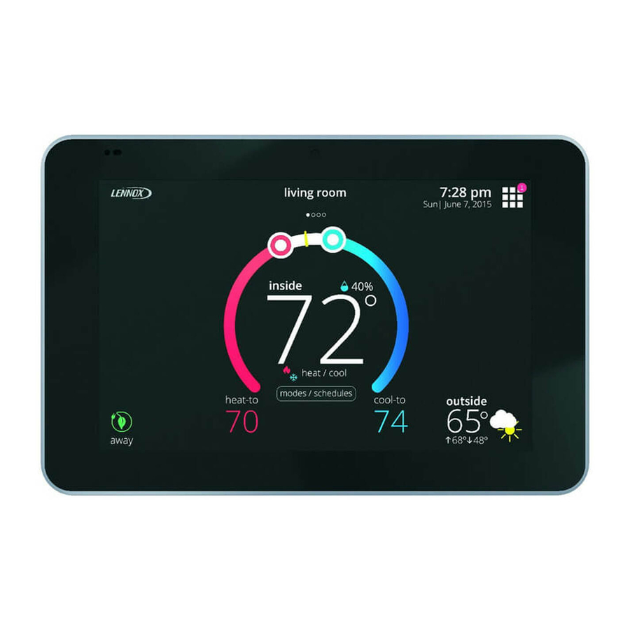
Lennox iComfort S30 Installation And Setup Manual
Color touchscreen programmable wi-fi
communicating thermostat
Hide thumbs
Also See for iComfort S30:
- Installation and setup manual (100 pages) ,
- User manual (20 pages) ,
- Installation and setup manual (80 pages)

Related Manuals for Lennox iComfort S30


Summary of Contents for Lennox iComfort S30
-
Page 1: Installation And Setup
® iComfort S30 (12U67) Installation and Setup Guide Color Touchscreen Programmable Wi-Fi Communicating Thermostat 507326-01 04/15... -
Page 2: Table Of Contents
......... . Lennox wireless point-to-point connection to other Lennox Smart Hubs in home and other mobile devices running Lennox applications. -
Page 3: Installing Control System Components
INSTALLING CONTROL SYSTEM COMPONENTS Before beginning installation, note the type of equipment, number of stages, and Install Smart Hub to indoor unit or equipment that could induce unit vibration any accessories being installed. to the unit. exceed 300 feet (91m) run when using 18 GAUGE thermostat wire or larger allow load from any thermostat connection to be more than 1 AMP. -
Page 4: Hd Display Installation
HD DISPLAY INSTALLATION 3. Unfold both antennas to the vertical position. Adjustments may be required to optimized transmitting and receiving. 1. Line up HD display with MAG-MOUNT base. 2. Insert bottom of the HD display at 30 degree angle into tabs at bottom of the NOTE - DO NOT mount the Smart Hub to indoor unit, duct work or equipment that MAG-MOUNT wall base. -
Page 5: Wiring For Control System Components
WIRING FOR CONTROL SYSTEM COMPONENTS The figure below illustrates the basic Lennox communication control wiring to all system components. ® ® iComfort AIR HANDLER (AHC) iComfort FURNACE (IFC) OR AIR HANDLER (AHC) OPTIONAL DISCHARGE AIR SENSOR (SEE DAS NOTE ON PAGE 5) - Page 6 ® IComfort FURNACE (IFC) OR AIR HANDLER (AHC) EQUIPMENT INTERFACE MODULE (EIM) OPTIONAL DISCHARGE AIR SMART HUB SENSOR (SEE DAS NOTE ON PAGE 5) OPTIONAL OUTDOOR AIR SENSOR (SEE OAS NOTE ® ON PAGE 5) ICOMFORT SMART HUB INDOOR UNIT SETUP NOTE: CUT Y1-Y2 ON-BOARD LINK FOR 2-STAGE OUTDOOR...
- Page 7 AUXILIARY DEHUMIDIFIER MODELS HCWHD3-070 AND HCWHD-095 AUXILIARY DEHUMIDIFIER MODELS HCWHD-090 AND HCWHD-135 NOTE: HCWHD-065 IS NOT COMPATIBLE SPDT RELAY iComfort Smart-Hub HVAC EQUIPMENT iComfort iComfort Smart-Hub Enabled HVAC Unit ACITIES Figure 8. Optional Accessories Wiring (Dehumidifiers)
- Page 8 SLP98 & G71MPP FURNACE (IFC) OR AIR HANDLER (AHC) FOR SL290 & EL296, SEE HUMIDIFIER DIAGRAM BELOW (BOTTOM RIGHT) NOTE: 24V UV LIGHT APPLICATIONS OPTIONAL DISCHARGE ® IN AN ICOMFORT SYSTEM, NEITHER FURNACE NOR AIR HANDLER TRANSFORMER AIR SENSOR (SEE DAS WILL HAVE ADEQUATE VA TO POWER 24V UV LIGHT APPLICATIONS.
- Page 9 ICOMFORT 2-STAGE LVCS VENTILATION CONTROL ICOMFORT FURNACE SYSTEM SLP98 & G71MPP FURNACE FURNACE ICOMFORT (IFC) OR AIR HANDLER (AHC) OR AIR OUTDOOR AIR HANDLER CONDITIONING OR HEAT PUMP R-DS W914 SMART HUB (POWER COMPANY INTERRUPTION SYSTEMS ARE WIRED SAME AS OVERFLOW SWITCH) RSBUS STANDARD 1 OR 2 STAGE...
-
Page 10: Configuring Heat Sections On Air Handler Control
CONFIGURATING HEAT SECTIONS ON AIR HANDLER CONTROL IMPORTANT: PRIOR TO RUNING THE ICOMFORT S30 INSTALLER SETUP, Air Handler Control ELECTRIC HEAT MUST BE MANUALLY CONFIGURED! IMPORTANT: After electric heat strips are installed, the air handler control must be FUSE 3 AMP... -
Page 11: Smart Hub Operations
Wi-Fi network in that it provides a means for devices to communicate with each other. A Lennox-managed local network is different from the home LAN in that it allows only Lennox devices to connect to it. A Lennox-managed local network operates only between:... -
Page 12: Smart Hub Indicators And Connectors
The center push button has a RGB (red-green-blue) LED backlight that indicates depicting Smart Hub functions and are back-lit by the Lennox-managed local network communication status of the Smart Hub, and LEDs. From left to right: if the Smart Hub is transferring a software image from a flash drive plugged into The Smart Hub using spring loaded the USB port. -
Page 13: Connecting Mobile Application To Smart Hub
BUTTON (LED RING) RESTARTING SMART HUB RESETTING SMART HUB - Pressing the center Lennox button for more than 5 seconds will restart the SMART HUB. ICOMFORT SMART HUB NORMAL CONDITION * SMART-HUB WI-FI is a self-contained Wi-Fi network (peer-to-peer) hosted by the SMART-HUB and totally independent of any other local network. -
Page 14: Installer System Setup
Here either the dealer ID and/or phone number can be added. When the system is connected to the Internet, the remaining information is automatically populated by the Lennox server. All information can be entered manually if desired however. NOTE: Not all information for this screen is viewable on a single screen. Use a finger to swipe up to access the remaining information on the screen. - Page 15 NOTE: When a Lennox Equipment Interface Module (EIM) is used and configured IHARMONY ZONING either as a furnace or air handler, then the component would appear as either This screen will only appear if the iHarmony® zoning system is detected.
-
Page 16: Dealer Control Center
DEALER CONTROL CENTER This menu provides access to the dealer for performing various functions as listed below: Use to run test on system components Use to run Use to display system diagnostics on maintenance history system components tests maintenance diagnostics history Use to display system notifications... -
Page 17: Equipment - System
The following is a complete list of all possible parameters under System. Range is 85 to 130ºF. Default is 85ºF. Adjustments can be made in increments of Parameters actually available are dependent on the Lennox communicating 15ºF. equipment type detected and non-communicating equipment added. - Page 18 MODULATING GAS HEATING STEP CHANGE PI GAIN (SLP98V ONLY) Three*stage heat: 1st stage provides 60% of full capacity; 2nd stage provides 80% of full capacity; 3rd stage provides 100% of full capacity. This is applicable to the SLP98V only. Step change gains deal with set point changes and affects how fast the system reaches the next set point (Example: Four*stage heat: 1st stage provides 35 or 40% of full capacity;...
- Page 19 AUX HEATING ACTIVATION THRESHOLD PARAMETERS DESCRIPTIONS This is an adjustment to hasten or delay the aux heat activation. This adjusts how SSP HEATING CANCEL COAST COUNTER Range is 0 to 0.75°F. Default is 0.25°F. Adjust INCREMENT SLOPE ments are in increments of 0.12°F far below the set point the temperature must fall with the HP at 100% before allowing electric heat to come on.
- Page 20 STAGE DELAY TIMERS LOW BALANCE POINT Setting used to prevent the heat pump from heating the structure. (Alert 18 - Minor - Enabled setting: When "ON" all stage delay timers (stages 2 through 6) are Notification only - The outdoor temperature is below the level where the heat pump enabled and will serve to bring on additional stage(s) of cooling or heating on a is programmed to heat the home) timed basis (default 20 minutes) Disabled setting: All stages delay timers are...
- Page 21 OUTDOOR TEMPERATURE READING CALIBRATION ZONING ANTICIPATED DISCHARGE AIR TEMPERATURE ADJUSTMENT This parameter setting compensates for a rapid change of the discharge air Range is -10 to 10°F. Default is 0°F. Adjustments are in increments of 1°F. This will temperature due to fast changing conditions. It examines the change in the allow for adjustment to the outdoor temperature display when the display discharge air temperature for the previous 2 minutes and extrapolates or looks temperature is off.
-
Page 22: Equipment - Heat Pump
ZONE 1 THROUGH 4 FIRST STAGE DIFFERENTIAL ADVANCED SETTINGS Options available are: Differential is the temperature between when first stage will cycle ON and cycle OFF. (Example: Zone 1 HD Display is set at 70°F with a 1.0°F differential. Cooling Restart Smart Hub (reboots Smart Hub). - Page 23 HIGH NORMAL COOLING AIRFLOW (XP20 AND XP25) DEHUM AIRFLOW ADJUSTMENT ADDER (XP20 AND XP25 ONLY) The range is 450 - 2150 CFM. Default is dependent on unit capacity with an ® Dehumidification airflow = “HUMID” Mode CFM table value for a given iComfort incremental adjustment of 25 CFM.
-
Page 24: Equipment - Air Conditioner
AIR HANDLER number, outdoor inverter firmware version, outdoor fan RPM profile, unit code, compatible devices list, application code memory size and micro-controller part The following is information on all possible available parameters for Lennox number. communicating air handlers. EQUIPMENT NAME... -
Page 25: Equipment - Furnace
AIRFLOW PROFILE - COOLING HP INDOOR BLOWER OFF DELAY The range is 0 - 60 seconds. Default is 45 seconds with an incremental adjustment Options are: of 5 seconds. 1 - no delays Heat Pump Indoor Blower OFF Delay (Heat Pump only - Blower runs at continuous air CFM setting during delay timing period) 2 - ON: 100% - finish cycle - 45 second delay off. -
Page 26: Equipment - Thermostat (Hd Display)
HEATING INDOOR BLOWER ON DELAY THERMOSTAT (HD DISPLAY) The range is 15 - 45 seconds with a default setting base on equipment type match-up. Adjustment are increments of 5 seconds. ABOUT HEATING AIRFLOW CONTROL TYPE This screen provides information concerning model number, serial number, Options for this setting are fixed CFM or fixed DAT (discharge air temperature). -
Page 27: Equipment - Zoning Control
ZONES 1 THROUGH 4 TEMP READING CALIBRATION ZONING CONTROL Allows adjustment to temperature reading displayed on zone thermostat. RESET ZONING CONTROL ABOUT Any installer modifications under the zoning control tab will be reset back to the This provides information on unit code, language supported, equipment type factory defaults if the reset zoning control option is used. -
Page 28: Alert Codes And Troubleshooting
NOTIFICATIONS These screens provide information on active notifications and previously cleared notifications. When selecting either a cleared or active notification a brief description and alert code will be displayed. Notifications are categorized by system, indoor unit (air handler or furnace), outdoor unit (air conditioner or heat pump), zoning control (if ®... - Page 29 Critical alerts are displayed on the Home screen, in the Homeowner alert button, and in the Installer alert button. Minor and Table 1. Alert Codes and Troubleshooting moderate alerts are found only in the Installer alert button. Applicable Alert Priority System Alert Text Component or System Operational State and Troubleshooting Tip...
- Page 30 Critical alerts are displayed on the Home screen, in the Homeowner alert button, and in the Installer alert button. Minor and Table 1. Alert Codes and Troubleshooting moderate alerts are found only in the Installer alert button. Applicable Alert Priority System Alert Text Component or System Operational State and Troubleshooting Tip...
- Page 31 Critical alerts are displayed on the Home screen, in the Homeowner alert button, and in the Installer alert button. Minor and Table 1. Alert Codes and Troubleshooting moderate alerts are found only in the Installer alert button. Applicable Alert Priority System Alert Text Component or System Operational State and Troubleshooting Tip...
- Page 32 Critical alerts are displayed on the Home screen, in the Homeowner alert button, and in the Installer alert button. Minor and Table 1. Alert Codes and Troubleshooting moderate alerts are found only in the Installer alert button. Applicable Alert Priority System Alert Text Component or System Operational State and Troubleshooting Tip...
- Page 33 Critical alerts are displayed on the Home screen, in the Homeowner alert button, and in the Installer alert button. Minor and Table 1. Alert Codes and Troubleshooting moderate alerts are found only in the Installer alert button. Applicable Alert Priority System Alert Text Component or System Operational State and Troubleshooting Tip...
- Page 34 Critical alerts are displayed on the Home screen, in the Homeowner alert button, and in the Installer alert button. Minor and Table 1. Alert Codes and Troubleshooting moderate alerts are found only in the Installer alert button. Applicable Alert Priority System Alert Text Component or System Operational State and Troubleshooting Tip...
- Page 35 Critical alerts are displayed on the Home screen, in the Homeowner alert button, and in the Installer alert button. Minor and Table 1. Alert Codes and Troubleshooting moderate alerts are found only in the Installer alert button. Applicable Alert Priority System Alert Text Component or System Operational State and Troubleshooting Tip...
- Page 36 Critical alerts are displayed on the Home screen, in the Homeowner alert button, and in the Installer alert button. Minor and Table 1. Alert Codes and Troubleshooting moderate alerts are found only in the Installer alert button. Applicable Alert Priority System Alert Text Component or System Operational State and Troubleshooting Tip...
- Page 37 Critical alerts are displayed on the Home screen, in the Homeowner alert button, and in the Installer alert button. Minor and Table 1. Alert Codes and Troubleshooting moderate alerts are found only in the Installer alert button. Applicable Alert Priority System Alert Text Component or System Operational State and Troubleshooting Tip...
- Page 38 Critical alerts are displayed on the Home screen, in the Homeowner alert button, and in the Installer alert button. Minor and Table 1. Alert Codes and Troubleshooting moderate alerts are found only in the Installer alert button. Applicable Alert Priority System Alert Text Component or System Operational State and Troubleshooting Tip...
- Page 39 Critical alerts are displayed on the Home screen, in the Homeowner alert button, and in the Installer alert button. Minor and Table 1. Alert Codes and Troubleshooting moderate alerts are found only in the Installer alert button. Applicable Alert Priority System Alert Text Component or System Operational State and Troubleshooting Tip...
- Page 40 Critical alerts are displayed on the Home screen, in the Homeowner alert button, and in the Installer alert button. Minor and Table 1. Alert Codes and Troubleshooting moderate alerts are found only in the Installer alert button. Applicable Alert Priority System Alert Text Component or System Operational State and Troubleshooting Tip...
- Page 41 Critical alerts are displayed on the Home screen, in the Homeowner alert button, and in the Installer alert button. Minor and Table 1. Alert Codes and Troubleshooting moderate alerts are found only in the Installer alert button. Applicable Alert Priority System Alert Text Component or System Operational State and Troubleshooting Tip...
- Page 42 Critical alerts are displayed on the Home screen, in the Homeowner alert button, and in the Installer alert button. Minor and Table 1. Alert Codes and Troubleshooting moderate alerts are found only in the Installer alert button. Applicable Alert Priority System Alert Text Component or System Operational State and Troubleshooting Tip...
- Page 43 Critical alerts are displayed on the Home screen, in the Homeowner alert button, and in the Installer alert button. Minor and Table 1. Alert Codes and Troubleshooting moderate alerts are found only in the Installer alert button. Applicable Alert Priority System Alert Text Component or System Operational State and Troubleshooting Tip...
- Page 44 Critical alerts are displayed on the Home screen, in the Homeowner alert button, and in the Installer alert button. Minor and Table 1. Alert Codes and Troubleshooting moderate alerts are found only in the Installer alert button. Applicable Alert Priority System Alert Text Component or System Operational State and Troubleshooting Tip...
-
Page 45: 434-438 Alert Codes
Critical alerts are displayed on the Home screen, in the Homeowner alert button, and in the Installer alert button. Minor and Table 1. Alert Codes and Troubleshooting moderate alerts are found only in the Installer alert button. Applicable Alert Priority System Alert Text Component or System Operational State and Troubleshooting Tip... - Page 46 Critical alerts are displayed on the Home screen, in the Homeowner alert button, and in the Installer alert button. Minor and Table 1. Alert Codes and Troubleshooting moderate alerts are found only in the Installer alert button. Applicable Alert Priority System Alert Text Component or System Operational State and Troubleshooting Tip...
- Page 47 Critical alerts are displayed on the Home screen, in the Homeowner alert button, and in the Installer alert button. Minor and Table 1. Alert Codes and Troubleshooting moderate alerts are found only in the Installer alert button. Applicable Alert Priority System Alert Text Component or System Operational State and Troubleshooting Tip...
- Page 48 Critical alerts are displayed on the Home screen, in the Homeowner alert button, and in the Installer alert button. Minor and Table 1. Alert Codes and Troubleshooting moderate alerts are found only in the Installer alert button. Applicable Alert Priority System Alert Text Component or System Operational State and Troubleshooting Tip...
-
Page 49: Maintenance History
S30 IS ASSOCIATED WITH YOUR DAVENET ACCOUNT WHEN is detected by the system then zones 1 through 4 will be listed. These screens allow CONNECTIONG TO THE LENNOX SERVER. for verification and modification of CFMs for blower, heating and cooling circulation. -
Page 50: System Configurations
SYSTEM CONFIGURATIONS ® COMPLETE ICOMFORT SYSTEMS — FURNACE AND AIR CONDITIONER ® ® An iComfort gas furnace (G71MPP, EL296V, SLP98, SL280) with an iComfort 5. From the equipment list, press Furnace. From this furnace screen you will air conditioner (XC17, XC20, XC21 or XC25 only) unit. have access to the various airflow settings. - Page 51 ® COMPLETE ICOMFORT SYSTEMS — FURNACE AND HP UNIT (DUAL-FUEL) ® Dual fuel system using an iComfort gas furnace (G71MPP, EL296V, SLP98, 6. Complete Balance Point Control by editing the High and Low Balance Points. ® SL280) with an iComfort heat pump (XP17, XP17N, XP21, XP21N and XP25 It is not necessary to change the defaults.
- Page 52 ® COMPLETE ICOMFORT SYSTEMS — AIR HANDLER AND AIR CONDITIONER ® ® An iComfort air handler (CBX32MV or CBX40UHV) with an iComfort 5. During the Installer System Setup (see page 14) you will end that process conditioner (XC17, XC20, XC21 or XC25 only). with the dealer control center.
- Page 53 ® COMPLETE ICOMFORT SYSTEMS — AIR HANDLER AND HEAT PUMP UNIT ® ® An iComfort air handler (CBX32MV or CBX40UHV) with an iComfort heat pump 6. Select Balance Point Control and press edit. Use the down arrow to select (XP17, XP17N, XP21, XP21N or XP25) unit. Enabled.
- Page 54 ® ® Partial iComfort System — iComfort Furnace and Non-Communicating Lennox Brand (Conventional) Heat Pump Unit (Dual-Fuel) ® ® If using a conventional non-communicating heat pump unit in an iComfort dual-fuel system then a iComfort Equipment Interface Module must be used and set up as a...
- Page 55 11. Under the select test to run, you may un-check any test not required, or run 3. On air handler control, when matched with conventional Lennox brand 2stage all test. Press start tests to proceed. Once each test section is completed, air conditioner, cut the Y1Y2 2 stage comp onboard clippable link.
- Page 56 ® ® PARTIAL ICOMFORT SYSTEM — ICOMFORT AIR HANDLER AND NON-COMMUNICATING LENNOX BRAND (CONVENTIONAL) HEAT PUMP UNIT ® ® An iComfort air handler (CBX32MV or CBX40UHV) with a conventional 4. After the entire system is wired, power up the system and the iComfort non-communicating Lennox brand heat pump unit.
- Page 57 ® ® PARTIAL ICOMFORT SYSTEM — ICOMFORT EQUIPMENT INTERFACE MODULE ® The iComfort Equipment Interface Module (EIM) can be configured in the 4. During the Installer System Setup (see page 14) you will arrive at the following setups: equipment found screen. From there select non-communicating equipment to add non-communicating equipment.
- Page 58 PARTIAL ICOMFORT SYSTEM — ICOMFORT FURNACE AND NON-COMMUNICATING LENNOX BRAND (CONVENTIONAL) HEAT PUMP UNIT (DUAL-FUEL) If the HD Display System Setting only shows “heat only“ or “off“ choices and does not offer a choice for “cooling” you must “Install” the non-communicating air conditioning unit (see procedures above).
-
Page 59: Glossary
Dual-fuel systems optimize energy use by selecting the best source of SSA - Single set point fuel, like Lennox systems that combine an electric heat pump with a high-efficiency gas or oil furnace. SSID - Is a case sensitive, 32 alphanumeric character unique identifier attached... -
Page 60: Fcc Compliance
FCC COMPLIANCE STATEMENT — PART 15.19 RF EXPOSURE INFORMATION This device complies with Part 15 of the FCC Rules. This equipment complies with FCC radiation exposure limits set forth for an uncontrolled environment. In order to avoid the possibility of exceeding the FCC Operation is subject to the following two conditions: radio frequency exposure limits, human proximity to the antenna shall not be less 1. -
Page 61: Index
APPENDIX A - INDEX Brightness Value, 26 Compressor Shift Delay ON/OFF, 22 Add / Remove Equipment, 27 Compressor Short Cycle Delay, 22, 24 Advanced Settings, 22 Continuous Indoor Blower Airflow, 25 Air Conditioner, 24 Cooling Indoor Blower Off Delay, 25 About, 24 Cooling Indoor Blower On Delay, 25 Compressor Short Cycle Delay, 24... - Page 62 Heating Airflow Control Type, 26 High Heating Airflow, 26 Heating Indoor Blower Off Delay, 25 High HP Airflow, 25 Heating Indoor Blower On Delay, 26 High Normal Cooling Airflow, 23, 24 High Heating Airflow, 26 High Normal HP Heating Airflow, 23 Low Heating Airflow, 26 Home Address, 14, 49 Reset Furnace, 26...
- Page 63 Modulating Cooling Steady State PI Gain, 19 Smart Hub Operations, 11 Modulating Gas Heating Cycles Per Hour, 18 Smart Hub Wi-FI, 11 Smooth Setback Recovery, 17 Modulating Gas Heating Steady State PI Gain, 18 SSP Cooling Cancel Cast Counter Decrement Slope, 19 Modulating Gas Heating Step Change PI Gain, 18 SSP Cooling Cancel Cast Counter Increment Slope, 19 Modulating HP Heating Cycles Per Hour, 18...
- Page 64 Modulating Cooling Cycles Per Hour, 19 Modulating Cooling Steady State PI Gain, 19 Thermostat, 26 Modulating Gas Heating Cycles Per Hour, 18 About, 26 Modulating Gas Heating Steady State PI Gain, 18 Auto Brightness, 26 Modulating Gas Heating Step Change PI Gain, 18 Brightness Value, 26 Modulating HP Heating Cycles Per Hour, 18 Display Indoor Humidity, 26...