Lennox iComfort S30 Installation And Setup Manual
Hide thumbs
Also See for iComfort S30:
- Installation and setup manual (100 pages) ,
- User manual (20 pages) ,
- Installation and setup manual (64 pages)

Related Manuals for Lennox iComfort S30


Summary of Contents for Lennox iComfort S30
-
Page 1: Installation And Setup
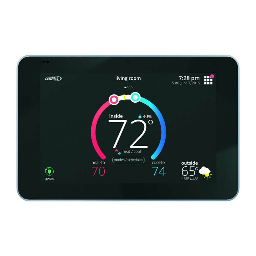
® iComfort Installation and Setup Guide Color Touchscreen Programmable Wi-Fi Communicating Thermostat (12U67) 507536-01 9/2015 Supersedes 7/2015... -
Page 2: Table Of Contents
........Partial iComfort® System — iComfort® Air Handler and Non-Communicating Lennox Brand (conventional) Air Conditioner . -
Page 3: Shipping And Packing List
Enhanced Dehumidification Accessory (EDA), ® personal communicating device. The iComfort S30 supports the following Enhance defrost control options for Lennox communicating heat pumps equipment and features: using Intellifrost™ Adaptive Defrost Control, part number 103369-04 or Wireless bands 802.11b, 802.11g and 802.11n,... -
Page 4: Installing Control System Components
INSTALLING CONTROL SYSTEM COMPONENTS Before beginning installation, note the type of equipment, number of stages, Install HD Display/Mag-Mount on outside walls or in direct sunlight. and any accessories being installed. Install Smart Hub to indoor unit or equipment that could induce unit vibration to the unit. -
Page 5: Mag-Mount Leds
Mag-Mount LEDs Power Button - Used for powering off and rebooting display for troubleshooting purposes. Press and hold for five seconds to turn off LED: A blue LED, mounted on the internal circuit board and is visible from display unit. Press and hold for five seconds to turn on unit. outside the Mag-Mount enclosure near the top-left corner when the HD Display SD Card Connector - for future use. -
Page 6: Smart Hub Installation
Smart Hub Installation CAUTION 1. Use the following procedure to install the Smart Hub controller. Refer to 1) Battery may need to charge before operation. Once the display figures 3 through 12 for making control wiring connections. is connected, instructions may appear within 15 seconds with 2. -
Page 7: Wiring For Control System Components
WIRING FOR CONTROL SYSTEM COMPONENTS The figure below illustrates the basic Lennox communication control wiring to all system components. ® iComfort ® FURNACE (IFC) OR AIR HANDLER (AHC) iComfort AIR HANDLER (AHC) OPTIONAL DISCHARGE AIR SENSOR OPTIONAL OUTDOOR OPTIONAL DISCHARGE AIR... - Page 8 ® IComfort FURNACE EQUIPMENT INTERFACE MODULE (EIM) (IFC) OR AIR HANDLER (AHC) OPTIONAL DISCHARGE AIR SMART HUB SENSOR (SEE DAS NOTE ON PAGE 7) OPTIONAL OUTDOOR AIR SENSOR (SEE OAS NOTE ON PAGE 7) SMART HUB ® ICOMFORT OUTDOOR UNIT SETUP NOTE: CUT Y1-Y2 ON-BOARD LINK FOR 24VAC FURNACE OR AIR...
- Page 9 AUXILIARY DEHUMIDIFIER MODELS HCWHD3-070 AND HCWHD-095 AUXILIARY DEHUMIDIFIER MODELS HCWHD-090 AND HCWHD-135 NOTE: HCWHD-065 IS NOT COMPATIBLE SPDT RELAY ④ SMART HUB ② ① ③ SMART HUB ICOMFORT MAG- INDOOR UNIT MOUNT ICOMFORT INDOOR UNIT MAG- MOUNT Figure 8. Optional Accessories Wiring (Dehumidifiers)
- Page 10 SLP98 & G71MPP FURNACE (IFC) OR AIR HANDLER (AHC) FOR SL280 & EL296, SEE HUMIDIFIER DIAGRAM BELOW OPTIONAL DIS (BOTTOM RIGHT) NOTE: 24V UV LIGHT APPLICATIONS CHARGE AIR SENSOR ® (SEE DAS NOTE ON IN AN ICOMFORT SYSTEM, NEITHER FURNACE NOR AIR HANDLER PAGE 7) TRANSFORMER WILL HAVE ADEQUATE VA TO POWER 24V UV LIGHT APPLI...
- Page 11 ICOMFORT 2-STAGE LVCS VENTILATION CONTROL ICOMFORT FURNACE SYSTEM SLP98 & G71MPP FURNACE FURNACE ICOMFORT (IFC) OR AIR HANDLER (AHC) OR AIR OUTDOOR AIR HANDLER CONDITIONING OR HEAT PUMP R-DS W914 SMART HUB (POWER COMPANY INTERRUPTION SYSTEMS ARE WIRED SAME AS OVERFLOW SWITCH) STANDARD 1 OR 2 STAGE AC OR HP UNIT...
- Page 12 S30 SMART HUB CONNECTIONS Figure 11. Wiring the Digital Ventilation Controller...
- Page 13 INDOOR UNIT CONTROLLER OUTDOOR UNIT ® ICOMFORT SMART HUB ® ICOMFORT MAG-MOUNT Single wire to 12VDC terminal C 12VDC Single wire to bundle Single wire to wire to indoor unit indoor unit terminal terminal C Single wire to terminal C Unused wires Unused wires Unused wires...
-
Page 14: Configurating Heat Sections On Air Handler Control
CONFIGURATING HEAT SECTIONS ON AIR HANDLER CONTROL IMPORTANT: PRIOR TO RUNNING THE ICOMFORT S30 INSTALLER Turn off power and connect all low voltage wiring. SETUP, ELECTRIC HEAT MUST BE MANUALLY CONFIGURED! Air Handler Control IMPORTANT: After electric heat strips are installed, the air handler control must be manually configured to detect the number of electric heat sections. -
Page 15: Smart Hub Operations
SMART HUB OPERATIONS local network is different from the home LAN in that it allows only Lennox devices to connect to it. A Lennox-managed local network operates only between a Smart Hub and a nearby Wi-Fi-capable mobile device running the iComfort ®... -
Page 16: Smart Hub Indicators And Connectors
Center Push Button Indicator The center push button has a RGB (red-green-blue) LED backlight that indicates the Lennox-managed local network communication status of the Figure 13. Smart Hub Indicators and Connectors Smart Hub, and if the Smart Hub is transferring a software image from a flash These LEDs have a red LED chip and a green LED chip in the package and drive plugged into the USB port. -
Page 17: Icomfort Mobile Setup Application
NOTE - If the system has not been commissioned it will go to reattached the HD Display to the Mag-Mount. commissioning screen. If the system has already been commissioned Go to the Smart Hub and press the center Lennox button once. it will go to dealer control center. -
Page 18: Service
Repeat entire procedure to reconnect. Go to the Smart Hub and touch the center Lennox button once. Restarting Smart Hub The center ring LED will start blinking green for two minutes. During that time the Smart Hub will broadcast its Wi-Fi identifier (SSID). -
Page 19: Installer System Setup
IMPORTANT: PRIOR TO RUNING THE ICOMFORT S30 INSTALLER the system is connected to the Internet, the remaining information is SETUP, AIR HANDLER ELECTRIC HEAT MUST BE MANUALLY automatically populated by the Lennox server. All information can be entered CONFIGURED! SEE PAGE 14. manually if desired however. -
Page 20: Equipment Found Screen
This screen allows you to rename each zone using provided preset names or NOTE - When a Lennox Equipment Interface Module (EIM) is used and ® custom name. This screen will not appear if iHarmony... -
Page 21: Dealer Control Center
Use to run test on < To navigate back to the dealer control center, system components touch on the Dave Lennox icon when available on the top left-hand side of the screen. < To navigate back to the previous screen, touch “Previous Screen... -
Page 22: Equipment
The following is a complete list of all possible parameters under System. heat to meet desired comfort levels. When the electric heat section is used in Parameters actually available are dependent on the Lennox communicating applications that do not have a heat pump, the elements are staged to limit heat equipment type detected and non-communicating equipment added. -
Page 23: Staged
Staged Less Aggressive is a set of slightly lower gains that will make the system less responsive and help to stabilize an oscillating system by sacrificing a Some furnaces can be configured to provide up to four stages of gas heat small amount of time to set point. - Page 24 Modulating HP Heating Step Change PI Gain (XP20 and XP25) Options are less aggressive, standard and more aggressive Default is standard. Step change gains deal with set point changes and affects how fast the system reaches the next set point (Example: Schedule change or adjustment to the Modulating Cooling Cycles Per Hour ®...
- Page 25 Disabled setting: All stages delay timers are disabled. Heat/cool stages PARAMETERS DESCRIPTIONS are changed based on temperature. When the outdoor temperature is above this setting, heating is not allowed if single set NOTE - The second-stage delay timer (when stage timers is Enabled) is used point is running.
- Page 26 Electric Heat Stages During Defrost Outdoor Temperature Reading Calibration Can increase or decrease the number of electric elements to come on during a Range is -10 to 10°F. Default is 0°F. Adjustments are in increments of 1°F. This ® will allow for adjustment to the outdoor temperature display when the display call for defrost.
- Page 27 Zoning Gas Heating DAT Cooldown Target Zoning Minimum Zone Run-Time Range is 90 to 600 seconds. Default is 120 seconds. Adjustments are in At the end of a gas cycle, the Heat Blower Off-Delay may not be long enough to increments of 30 seconds.
-
Page 28: Heat Pump
High Normal Cooling Airflow Heat Pump (XP20 and XP25) The range is 450 - 2150 CFM. Default is dependent on unit capacity with an The following is information on all possible available parameters. Parameters incremental adjustment of 25 CFM. listed are dependent on actual type of heat pump installed. ®... -
Page 29: Air Conditioner
RPM The following is information on all possible available parameters for Lennox profile, unit code, compatible devices list, application code memory size and communicating air handlers. -
Page 30: Furnace
High Cooling Airflow HP Indoor Blower Off Delay The range is 1560 to 2150 CFM. Default is based on cooling demand with an The range is 0 - 60 seconds. Default is 45 seconds with an incremental incremental adjustments of 5 CFM. adjustment of 5 seconds. - Page 31 Airflow Profile - Cooling HP Blower On Delay The range is 0.0 - 30.0 seconds with a default setting base on equipment type Options are: match-up. Adjustment are increments of 5 seconds. Default is 0.0 seconds. A - ON: 50% - 30 seconds at 82% - 7-1/2 minutes at 100% and finish cycle Heating Airflow Control Type 50% / 30 seconds off.
-
Page 32: Thermostat (Hd Display)
Thermostat (HD Display) Zoning Control About About This provides information on unit code, language supported, equipment type This screen provides information concerning model number, serial number, name, control software revision, control model number, control serial number, hardware revision, software revision, language support and equipment type control hardware revision, protocol revision number, device product level, name. -
Page 33: Notifications
S30 IS ASSOCIATED WITH YOUR DAVENET ACCOUNT heating and cooling circulation. Touch continue to proceed to the next screen. WHEN CONNECTING TO THE LENNOX SERVER. Select Test to Run is the next screen to appear. Depending on hardware present, various tests are available. By default all items to be tested are Warning Screen: If neither the dealer ID or phone number is provided, a enabled. -
Page 34: System Configurations
SYSTEM CONFIGURATIONS ® Complete iComfort Systems — Furnace and Air Conditioner ® An iComfort gas furnace (G71MPP, EL296V, SLP98, SL280) with an 5. From the equipment list, press Furnace. From this furnace screen you will ® iComfort air conditioner (SL18XC, XC17, XC20, XC21 or XC25 only) unit. have access to the various airflow settings. -
Page 35: Complete Icomfort® Systems - Furnace And Hp Unit (Dual-Fuel)
® Complete iComfort Systems — Furnace and HP Unit (Dual-fuel) ® Dual fuel system using an iComfort gas furnace (G71MPP, EL296V, SLP98, 6. Complete Balance Point Control by editing the High and Low Balance ® SL280) with an iComfort heat pump (SL18XP, XP17, XP17N, XP21, XP21N, Points. -
Page 36: Complete Icomfort® Systems - Air Handler And Air Conditioner
® Complete iComfort Systems — Air Handler and Air Conditioner ® ® An iComfort air handler (CBX32MV or CBX40UHV) with an iComfort 5. During the Installer System Setup (see page 19) you will end that process conditioner (SL18XC, XC17, XC20, XC21 or XC25). with the dealer control center screen. -
Page 37: Complete Icomfort® Systems - Air Handler And Heat Pump Unit
® Complete iComfort Systems — Air Handler and Heat Pump Unit ® ® An iComfort air handler (CBX32MV or CBX40UHV) with an iComfort heat 6. Select Balance Point Control and press edit. Use the down arrow to touch pump (SL18XP, XP17, XP17N, XP20, XP21, XP21N or XP25) unit. Enabled. -
Page 38: Partial Icomfort® System - Icomfort® Furnace And Non-Communicating Lennox Brand (Conventional) Air Conditioner
® ® Partial iComfort System — iComfort Furnace and Non-Communicating Lennox Brand (Conventional) Heat Pump Unit (Dual-Fuel) ® ® If using a conventional non-communicating heat pump unit in an iComfort dual-fuel system then a iComfort Equipment Interface Module must be used and set... -
Page 39: Partial Icomfort® System - Icomfort® Air Handler And Non-Communicating Lennox Brand (Conventional) Air Conditioner
Wiring as required for accessories. continue. 3. On air handler control, when matched with conventional Lennox brand 13. Under the touch test to run, you may un-check any test not required, or 2stage air conditioner, cut the Y1Y2 2 stage comp onboard clippable run all tests. -
Page 40: Brand (Conventional) Heat Pump Unit
® ® Partial iComfort System — iComfort Air Handler and Non-Communicating Lennox Brand (conventional) Heat Pump Unit ® ® An iComfort air handler (CBX32MV or CBX40UHV) with a conventional 4. After the entire system is wired, power up the system and the iComfort non-communicating Lennox brand heat pump unit. -
Page 41: Partial Icomfort® System - Icomfort® Equipment Interface Module
® ® Partial iComfort System — iComfort Equipment Interface Module ® The iComfort Equipment Interface Module (EIM) can be configured in the 4. During the Installer System Setup (see page 19) you will arrive at the following setups: equipment found screen. From there touch non-communicating equipment to add non-communicating equipment. -
Page 42: G71Mpp Or Slp98 Furnace Setting Adjustment
G71MPP or SLP98 Furnace Setting Adjustment ® ® If your iComfort S30 is being used with either a G71MPP or SLP98 furnace and is set to variable-capacity mode of operation (the iComfort default with these units), the system's settings for stage timers are ignored (even if shown enabled in the S30 Control System). The stage timer will be used on the cooling side for other cooling units except the XC20, SL18XC1/XP1 and XC/XP25 where they are not used. -
Page 43: Glossary
Dual-fuel systems optimize energy use by selecting the and other optional parameters to determine if the home is occupied in real time best source of fuel, like Lennox systems that combine an electric heat pump for the purpose of temperature set point setback. - Page 44 UVC - Refers to ultraviolet light with wavelengths between 200 – 280 TXV - The thermostatic expansion valve (TXV) is a precision device, which is designed to regulate the rate at which liquid refrigerant flows into the nanometers (nm). Light in the UVC wavelength can be used for disinfecting evaporator.
-
Page 45: Alert Codes And Troubleshooting
Moderate means that the system will likely recover on its own, no action necessary. Minor is information only, helps Lennox interpret test results, understand complicated behavior. Communication System: When communication controls are operating in a communication system, all jumper and link setting on controls are ignored. Jumpers and link setting are treated as defaults and would only be active if the system was converted to a non-communicating system. - Page 46 Critical alerts are displayed on the Home screen, in the Homeowner alert button, and in the Installer alert button. Table 1 Alert Codes and Troubleshooting Minor and moderate alerts are found only in the Installer alert button. Applicable Alert Priority Actual Displayed Alert System Component or System Operational State and Troubleshooting Tip...
- Page 47 Critical alerts are displayed on the Home screen, in the Homeowner alert button, and in the Installer alert button. Table 1 Alert Codes and Troubleshooting Minor and moderate alerts are found only in the Installer alert button. Applicable Alert Priority Actual Displayed Alert System Component or System Operational State and Troubleshooting Tip...
- Page 48 Critical alerts are displayed on the Home screen, in the Homeowner alert button, and in the Installer alert button. Table 1 Alert Codes and Troubleshooting Minor and moderate alerts are found only in the Installer alert button. Applicable Alert Priority Actual Displayed Alert System Component or System Operational State and Troubleshooting Tip...
- Page 49 Critical alerts are displayed on the Home screen, in the Homeowner alert button, and in the Installer alert button. Table 1 Alert Codes and Troubleshooting Minor and moderate alerts are found only in the Installer alert button. Applicable Alert Priority Actual Displayed Alert System Component or System Operational State and Troubleshooting Tip...
- Page 50 Critical alerts are displayed on the Home screen, in the Homeowner alert button, and in the Installer alert button. Table 1 Alert Codes and Troubleshooting Minor and moderate alerts are found only in the Installer alert button. Applicable Alert Priority Actual Displayed Alert System Component or System Operational State and Troubleshooting Tip...
- Page 51 Critical alerts are displayed on the Home screen, in the Homeowner alert button, and in the Installer alert button. Table 1 Alert Codes and Troubleshooting Minor and moderate alerts are found only in the Installer alert button. Applicable Alert Priority Actual Displayed Alert System Component or System Operational State and Troubleshooting Tip...
- Page 52 Critical alerts are displayed on the Home screen, in the Homeowner alert button, and in the Installer alert button. Table 1 Alert Codes and Troubleshooting Minor and moderate alerts are found only in the Installer alert button. Applicable Alert Priority Actual Displayed Alert System Component or System Operational State and Troubleshooting Tip...
- Page 53 Critical alerts are displayed on the Home screen, in the Homeowner alert button, and in the Installer alert button. Table 1 Alert Codes and Troubleshooting Minor and moderate alerts are found only in the Installer alert button. Applicable Alert Priority Actual Displayed Alert System Component or System Operational State and Troubleshooting Tip...
- Page 54 Critical alerts are displayed on the Home screen, in the Homeowner alert button, and in the Installer alert button. Table 1 Alert Codes and Troubleshooting Minor and moderate alerts are found only in the Installer alert button. Applicable Alert Priority Actual Displayed Alert System Component or System Operational State and Troubleshooting Tip...
- Page 55 Critical alerts are displayed on the Home screen, in the Homeowner alert button, and in the Installer alert button. Table 1 Alert Codes and Troubleshooting Minor and moderate alerts are found only in the Installer alert button. Applicable Alert Priority Actual Displayed Alert System Component or System Operational State and Troubleshooting Tip...
- Page 56 Critical alerts are displayed on the Home screen, in the Homeowner alert button, and in the Installer alert button. Table 1 Alert Codes and Troubleshooting Minor and moderate alerts are found only in the Installer alert button. Applicable Alert Priority Actual Displayed Alert System Component or System Operational State and Troubleshooting Tip...
- Page 57 Critical alerts are displayed on the Home screen, in the Homeowner alert button, and in the Installer alert button. Table 1 Alert Codes and Troubleshooting Minor and moderate alerts are found only in the Installer alert button. Applicable Alert Priority Actual Displayed Alert System Component or System Operational State and Troubleshooting Tip...
- Page 58 Critical alerts are displayed on the Home screen, in the Homeowner alert button, and in the Installer alert button. Table 1 Alert Codes and Troubleshooting Minor and moderate alerts are found only in the Installer alert button. Applicable Alert Priority Actual Displayed Alert System Component or System Operational State and Troubleshooting Tip...
- Page 59 Critical alerts are displayed on the Home screen, in the Homeowner alert button, and in the Installer alert button. Table 1 Alert Codes and Troubleshooting Minor and moderate alerts are found only in the Installer alert button. Applicable Alert Priority Actual Displayed Alert System Component or System Operational State and Troubleshooting Tip...
- Page 60 Critical alerts are displayed on the Home screen, in the Homeowner alert button, and in the Installer alert button. Table 1 Alert Codes and Troubleshooting Minor and moderate alerts are found only in the Installer alert button. Applicable Alert Priority Actual Displayed Alert System Component or System Operational State and Troubleshooting Tip...
- Page 61 Critical alerts are displayed on the Home screen, in the Homeowner alert button, and in the Installer alert button. Table 1 Alert Codes and Troubleshooting Minor and moderate alerts are found only in the Installer alert button. Applicable Alert Priority Actual Displayed Alert System Component or System Operational State and Troubleshooting Tip...
- Page 62 Critical alerts are displayed on the Home screen, in the Homeowner alert button, and in the Installer alert button. Table 1 Alert Codes and Troubleshooting Minor and moderate alerts are found only in the Installer alert button. Applicable Alert Priority Actual Displayed Alert System Component or System Operational State and Troubleshooting Tip...
- Page 63 Critical alerts are displayed on the Home screen, in the Homeowner alert button, and in the Installer alert button. Table 1 Alert Codes and Troubleshooting Minor and moderate alerts are found only in the Installer alert button. Applicable Alert Priority Actual Displayed Alert System Component or System Operational State and Troubleshooting Tip...
- Page 64 Critical alerts are displayed on the Home screen, in the Homeowner alert button, and in the Installer alert button. Table 1 Alert Codes and Troubleshooting Minor and moderate alerts are found only in the Installer alert button. Applicable Alert Priority Actual Displayed Alert System Component or System Operational State and Troubleshooting Tip...
- Page 65 Critical alerts are displayed on the Home screen, in the Homeowner alert button, and in the Installer alert button. Table 1 Alert Codes and Troubleshooting Minor and moderate alerts are found only in the Installer alert button. Applicable Alert Priority Actual Displayed Alert System Component or System Operational State and Troubleshooting Tip...
- Page 66 Critical alerts are displayed on the Home screen, in the Homeowner alert button, and in the Installer alert button. Table 1 Alert Codes and Troubleshooting Minor and moderate alerts are found only in the Installer alert button. Applicable Alert Priority Actual Displayed Alert System Component or System Operational State and Troubleshooting Tip...
- Page 67 Critical alerts are displayed on the Home screen, in the Homeowner alert button, and in the Installer alert button. Table 1 Alert Codes and Troubleshooting Minor and moderate alerts are found only in the Installer alert button. Applicable Alert Priority Actual Displayed Alert System Component or System Operational State and Troubleshooting Tip...
- Page 68 Critical alerts are displayed on the Home screen, in the Homeowner alert button, and in the Installer alert button. Table 1 Alert Codes and Troubleshooting Minor and moderate alerts are found only in the Installer alert button. Applicable Alert Priority Actual Displayed Alert System Component or System Operational State and Troubleshooting Tip...
- Page 69 Critical alerts are displayed on the Home screen, in the Homeowner alert button, and in the Installer alert button. Table 1 Alert Codes and Troubleshooting Minor and moderate alerts are found only in the Installer alert button. Applicable Alert Priority Actual Displayed Alert System Component or System Operational State and Troubleshooting Tip...
- Page 70 APPENDIX A - INDEX Heating Airflow Control Type, 31 Compressor Short Cycle Delay, 28, 29 Heating Indoor Blower Off Delay, 31 Continuous Indoor Blower Airflow, 30, 31 Heating Indoor Blower On Delay, 31 **Empty**, 2 Controls, Indoor, Outdoor, 42 High Heating Airflow, 31 High HP Airflow, 31 Cooling Indoor Blower Off Delay, 30, 31 HP Indoor Blower Off Delay, 31...
- Page 71 High Normal HP Heating Airflow, 28 Modulating HP Heating Cycles Per Hour, 24 Controller Installation, 6 Cooling Mode, 24 Home Address, 33 Modulating Step Change, Understanding, 23 Dew Point Adjustment, 26 HP Heating Lockout Temp, 27 Electric Heat Control, 22 Electric heat Stages During Defrost, 26 HP Heating Mode, 26 Equipment Name, 22...
- Page 72 Zoning Minimum Zone Run Time, 27 Stage Delays, 25 Wireless Bands, 3 Zoning Supply Air Temp Limit for Cooling, 27 Stage Differentials, 25 Wiring Diagrams, 7 Zoning Supply Air Temp Limit for Gas/Electric Heating, 27 Steady State PI Gains, Understanding, 23 Zoning Target Supply Air Temp for Cooling, 27 Zoning Target Supply Air Temp for Heating, 27 System, CCP Acceptable Standard Deviation -...