Table of Contents
Advertisement
Quick Links
Industrial Automation Headquarters
Delta Electronics, Inc.
Taoyuan Technology Center
No.18, Xinglong Rd., Taoyuan City,
Taoyuan County 33068, Taiwan
TEL: 886-3-362-6301 / FAX: 886-3-371-6301
Asia
Delta Electronics (Jiangsu) Ltd.
Wujiang Plant 3
1688 Jiangxing East Road,
Wujiang Economic Development Zone
Wujiang City, Jiang Su Province, P.R.C. 215200
TEL: 86-512-6340-3008 / FAX: 86-769-6340-7290
Delta Greentech (China) Co., Ltd.
238 Min-Xia Road, Pudong District,
ShangHai, P.R.C. 201209
TEL: 86-21-58635678 / FAX: 86-21-58630003
Delta Electronics (Japan), Inc.
Tokyo Office
2-1-14 Minato-ku Shibadaimon,
Tokyo 105-0012, Japan
TEL: 81-3-5733-1111 / FAX: 81-3-5733-1211
Delta Electronics (Korea), Inc.
1511, Byucksan Digital Valley 6-cha, Gasan-dong,
Geumcheon-gu, Seoul, Korea, 153-704
AH500 Operation Manual
TEL: 82-2-515-5303 / FAX: 82-2-515-5302
Delta Electronics Int'l (S) Pte Ltd.
4 Kaki Bukit Ave 1, #05-05, Singapore 417939
TEL: 65-6747-5155 / FAX: 65-6744-9228
Delta Electronics (India) Pvt. Ltd.
Plot No 43 Sector 35, HSIIDC
Gurgaon, PIN 122001, Haryana, India
TEL : 91-124-4874900 / FAX : 91-124-4874945
Americas
Delta Products Corporation (USA)
Raleigh Office
P.O. Box 12173,5101 Davis Drive,
Research Triangle Park, NC 27709, U.S.A.
TEL: 1-919-767-3800 / FAX: 1-919-767-8080
Delta Greentech (Brasil) S.A.
Sao Paulo Office
Rua Itapeva, 26 - 3° andar Edificio Itapeva One-Bela Vista
01332-000-São Paulo-SP-Brazil
TEL: 55 11 3568-3855 / FAX: 55 11 3568-3865
Europe
Deltronics (The Netherlands) B.V.
Eindhoven Office
De Witbogt 20, 5652 AG Eindhoven, The Netherlands
TEL: 31-40-2592850 / FAX: 31-40-2592851
AH-0109420-05
*We reserve the right to change the information in this manual without prior notice.
www.deltaww.com
2018-05-15
Advertisement
Chapters
Table of Contents
Troubleshooting

Related Manuals for Delta Electronics AH500


Summary of Contents for Delta Electronics AH500
- Page 1 1511, Byucksan Digital Valley 6-cha, Gasan-dong, Geumcheon-gu, Seoul, Korea, 153-704 AH500 Operation Manual TEL: 82-2-515-5303 / FAX: 82-2-515-5302 Delta Electronics Int’l (S) Pte Ltd. 4 Kaki Bukit Ave 1, #05-05, Singapore 417939 TEL: 65-6747-5155 / FAX: 65-6744-9228 Delta Electronics (India) Pvt. Ltd.
- Page 2 AH500 Operation Manual Revision History Ve r s i o n R e v i s i o n D a t e 1 . T h e f i r s t v e r s i o n w a s p u b l i s h e d .
- Page 3 Ve r s i o n R e v i s i o n D a t e r a n g e i s u p d a t e d i n s e c t i o n 5 . 1 . 4 . 5 .
-
Page 4: Table Of Contents
AH500 Operation Manual Table of Contents Chapter 1 Introduction Introduction ....................1-2 1.1.1 Related Manuals ................1-2 1.1.2 Description of Models ................ 1-2 Overview ....................1-8 Characteristics ..................1-10 Chapter 2 Specifications and System Configuration General Specifications................2-3 Specifications for CPU Modules ............... 2-3 2.2.1... - Page 5 Specifications for Network Modules ............2-53 2.7.1 General Specifications ..............2-53 2.7.2 Profiles ..................... 2-56 2.7.3 Dimensions ..................2-65 2.7.4 Arrangement of Input/Output Terminals ........... 2-68 2.7.5 Setting Parameters ................2-69 Specifications for Motion Control Modules ..........2-72 2.8.1 General Specifications ..............2-72 2.8.2 Profiles .....................
- Page 6 Wiring ....................... 4-5 4.2.1 Wiring a Power Supply Module ............4-5 4.2.2 Wiring I/O Modules ................4-7 Chapter 5 Devices 5.1 Introduction of Devices .................. 5-2 5.1.1 Devise Table ..................5-2 5.1.2 Basic Structure of I/O Storages ............5-4 5.1.3 Relation Between the PLC Action and the Device Type ....
- Page 7 6.5.1 Adding a Ladder Diagram ..............6-8 Basic Editing─Creating a Contact and a Coil ........6-10 6.5.2 Basic Editing─Inserting a Network and Typing an Instruction ..6-13 6.5.3 Basic Editing─Selection of a Network and Operation ...... 6-15 6.5.4 Basic Editing─Connecting a Contact in Parallel ....... 6-16 6.5.5 Basic Editing─Editing a Comment ...........
- Page 8 Cutting/Copying/Pasting an Extension Rack ......8-25 8.1.2.14 Dragging an Extension Rack .............8-28 8.1.2.15 Rearranging the Input/Output Devices ........8-28 Setting the Parameters in an AH500 Series CPU Module .......8-29 8.2.1 Opening the PLC Parameter Setting Window ........8-29 8.2.2 Setting the Basic CPU Parameters ..........8-30 8.2.2.1...
- Page 9 Exporting and Importing the Parameters in a Module ...... 8-56 8.3.4 Setting the Parameters in an Intelligent Module....... 8-57 Management of the Parameters in AH500 Series Hardware and Online Diagnosis ....................8-58 8.4.1 Saving and Printing a Hardware Configuration ........ 8-58 8.4.2...
- Page 10 9.2.6 Correct Network Architecture ............9-30 9.2.7 Downloading Routing Tables ............9-33 9.2.8 Testing Routing.................9-34 Managing and Applying NWCONFIG ............9-36 9.3.1 Saving Parameters and Printing a Network Framework ....9-36 9.3.2 Downloading Parameters ..............9-37 9.3.2.1 Introduction of Parameters ............9-37 9.3.2.2 Description of Downloading Parameters ........9-38 9.3.3 Using Routing in ISPSoft ..............9-39 Chapter 10 Operating Principle of the CPU Module...
- Page 11 11.2.2.2 Opening the Ether Link Configuration Window ....... 11-36 11.2.2.3 Creating and Managing a Data Exchange Table ....11-38 11.2.2.4 Node List and Display Area ............ 11-41 11.2.2.5 Start Mode of an Ether Link ............ 11-43 11.2.2.6 Downloading the Parameters Related to an Ether Link ..11-45 11.2.2.7 Uploading the Parameters Related to an Ether Link ....
- Page 12 A.1 Installing the USB Driver for an AH500 Series CPU module in Windows XP with SP3 ....................... A-2 A.2 Installing the USB Driver for an AH500 Series CPU module in Windows 7 .. A-6 A.3 Installing the USB Driver for an AH500 Series CPU module in Windows 8 ..
- Page 13 A.4 Installing the USB Driver for an AH500 Series CPU module in Windows 10 .......................... A-13 Appendix B Device Addresses Device Addresses ..................B-2...
- Page 14 Chapter 1 Introduction Table of Contents Introduction ......................1-2 1.1.1 Related Manuals ..................1-2 1.1.2 Description of Models .................. 1-2 Overview ......................1-8 Characteristics ....................1-10 1 - 1...
-
Page 15: Chapter 1 Introduction
1.1 Introduction This manual introduces functions of CPUs, devices, module tables, troubleshooting, and etc. 1.1.1 Related Manuals The related manuals of the AH500 series programmable logic controllers are composed of the following AH500 Quick Start It guides users to use the system before they read the related manuals. - Page 16 C h a p t e r 1 I n t r o d u c t i o n Classification Model Name Description is 64K steps. It is an advanced CPU module with two built-in RS-485 ports, AHCPU511-RS2 one built-in USB port, and one built-in SD interface. It supports 1280 inputs/outputs.
- Page 17 A H 5 0 0 O p e r a t i o n M a n u a l Classification Model Name Description module 16 inputs Terminal block 24 V DC 5 mA AH32AM10N-5A 32 inputs Terminal block 24 V DC 5 mA AH32AM10N-5B 32 inputs...
- Page 18 C h a p t e r 1 I n t r o d u c t i o n Classification Model Name Description Sinking output Latch connector 12~24 V DC 0.1 A AH32AN02P-5A 32 outputs Sourcing output Terminal block 12~24 V DC 0.1 A AH32AN02P-5B...
- Page 19 A H 5 0 0 O p e r a t i o n M a n u a l Classification Model Name Description Terminal block Four-channel analog input module Hardware resolution: 16 bits AH04AD-5A 0/1 V~5 V, -5 V~5 V, 0 V~10 V, -10 V~10 V, 0/4 mA~20 mA, and -20 mA~20 mA Conversion time: 150 us/channel Eight-channel analog input module...
- Page 20 C h a p t e r 1 I n t r o d u c t i o n Classification Model Name Description Four-channel thermocouple Sensor type: J, K, R, S, T, E, N, and -150~+150 mV AH04TC-5A Resolution: 0.1°C/0.1°F Conversion time: 200 ms/channel Eight-channel thermocouple Sensor type: J, K, R, S, T, E, N, and -150~+150 mV...
-
Page 21: Overview
Space module used for an empty I/O slot 1.2 Overview An AH500 series CPU module is a medium type of advanced controller with built-in communication ports. It provides a strong network function for users, and users can create connection among devices on the network through software. - Page 22 It provides a strong network function for users, and users can create connection among devices in the network through software. Users can restore or back up a system rapidly through the built-in SD interface in an AH500 series CPU module.
-
Page 23: Characteristics
Supporting more inputs and outputs The AH500 series CPU module supports up to 4,352 local digital I/O or 544 analog I/O. A complete AH500 system consists of eight backplanes at most, including a main backplane. Twelve I/O modules at most can be installed on a main backplane, and eight I/O modules at most can be installed on an extension backplane. - Page 24 An AH500 series CPU module is equipped with devices which can be used conveniently in a program. Users can flexibly specify a bit in a word device, e.g. D0.0, X0.0, and Y0.0. Owing to that bits in a word device can be specified, these bits can function as contacts and coils.
- Page 25 Not only the standard IEC61131-3 function blocks are supported, but also the convenient function blocks provided by Delta Electronics, Inc. are supported. Users can write the program frequently executed in a function block so that the program becomes more structured and can be executed more conveniently.
- Page 26 Increasing the efficiency of configuring the hardware through an USB cable and ISPSoft The AH500 series CPU module provides a standard USB 2.0 interface. USB 2.0 increases the data transfer rate, and decreases the time it takes to download the program, monitor the program and configure the hardware.
- Page 27 The data transfer rate can be increased from 9600 bps to 1 Mbps. AH500 basic series CPU module (AHCPU500/510/520/530): After users set the PLC Link in NWCONIFG in ISPSoft, they can exchange the data with a device through the RS-485 serial control interface, and do not need to write any program.
- Page 28 14. Supporting the on-line debugging mode After a single instruction step has been complete, or after a breakpoint is specified, users can easily find the bug in the program by means of the on-line debugging mode supported by the AH500 series CPU module. ...
- Page 29 A H 5 0 0 O p e r a t i o n M a n u a l Step 2: Entering the on-line mode Step 3: Entering the debugging mode 15. Supporting the on-line editing mode When the system runs, users can make use of the on-line editing mode to update the program without affecting the operation of the system.
- Page 30 C h a p t e r 1 I n t r o d u c t i o n After the program is modified and compiled, users can update the program in the CPU module by clicking 1 - 1 7...
- Page 31 A H 5 0 0 O p e r a t i o n M a n u a l MEMO 1 - 1 8...
-
Page 32: Chapter 2 Specifications And System Configuration
Chapter 2 Specifications and System Configuration Table of Contents General Specifications ..................2-3 Specifications for CPU Modules ................2-3 2.2.1 Performance Specifications ................. 2-3 2.2.2 Profiles ......................2-6 Basic System Configuration ................2-8 2.3.1 Introduction ....................2-8 2.3.2 Configuring a Main Backplane ..............2-9 2.3.3 Configuring an Extension Backplane ............ - Page 33 2.11.1 General Specifications ................. 2-110 2.11.2 Profiles....................2-111 2.11.3 Dimensions ..................2-114 2 - 2...
-
Page 34: General Specifications
IEC 61131-2 & IEC 68-2-27 (TEST Ea) Work environment No corrosive gas exists. Installation location In a control box Pollution degree 2.2 Specifications for CPU Modules 2.2.1 Performance Specifications of AH500 basic series AHCPU500/510/520/530 AHCPU500/510/520/530 Item Remark -RS2 Execution The program is executed cyclically. -
Page 35: Performance Specifications
SD Card (SD 1.0) Remote RUN/STOP The setting range is X0.0~X511.15. Years, months, days, hours, minutes, seconds, and Real-time clock weeks 2.2.2 Performance Specifications of AH500 advanced series AHCPU501/511/521/531- AHCPU501/511/521/531 Item Remark Execution The program is executed cyclically. Regenerated inputs/outputs... - Page 36 A H 5 0 0 O p e r a t i o n M a n u a l AHCPU501/511/521/531- AHCPU501/511/521/531 Item Remark controlled through the direct inputs and direct outputs. IEC 61131-3 Ladder diagrams, function block diagrams, Programming language instruction lists, structured texts, and sequential function charts Instruction execution speed 12K Steps/ms...
-
Page 37: Profiles
Years, months, days, hours, minutes, seconds, and Real-time clock weeks 2.2.3 Profiles An AH500 system can be configured by setting the following communication ports. Three built-in communication ports (USB port, RS-232C/RS-422A/RS-485 port, and Ethernet port) AHCPU5X0-EN (AHCPU500-EN/ AHCPU510-EN/ AHCPU520-EN/ AHCPU530-EN) AHCPU5X1-EN (AHCPU501-EN/ AHCPU511-EN/ AHCPU521-EN/ AHCPU531-EN) - Page 38 A H 5 0 0 O p e r a t i o n M a n u a l Two built-in communication ports (RS-232C port and RS-422A/RS-485 port) AHCPU5X1-RS2 (AHCPU501-RS2/ AHCPU511-RS2/ AHCPU521-RS2/ AHCPU531-RS2) CPU530-RS2 ERROR BUS FAULT SYSTEM COM1 COM2 1.
-
Page 39: Basic System Configuration
2.3.1 Introduction The AH500 system configuration is composed of a CPU module, power supply modules, digital input/output modules, analog input/output modules, temperature measurement modules, network modules, motion control modules, a main backplane, extension cables, and extension backplanes. Besides, an SD card is optionally used. -
Page 40: Configuring A Main Backplane
A H 5 0 0 O p e r a t i o n M a n u a l Main backplane Extension cable Extension backplane 1 Extension backplane 2 2.3.2 Configuring a Main Backplane A CPU module, a power supply module, and I/O modules are installed on a main backplane. Twelve I/O modules at most can be installed on a main backplane. -
Page 41: Configuring An Extension Backplane
C h a p t e r 2 Sp e c i f i c a t i o n s a n d S y s t e m C o n f i g u r a t i o 2.3.3 Configuring an Extension Backplane An extension backplane can be connected to a main backplane to increase the number of I/O modules. -
Page 42: Specifications For Digital Input/Output Modules
The voltages of the direct currents which can flow into AHPS15-5A are 24 V, and the direct currents which can flow form AHPS15-5A are 1.5 A.) There is one CPU module in an AH500 system, such as AHCPU5X0-RS2, CPU module AHCPU5X0-EN, AHCPU5X1-RS2, and AHCPU5X1-EN. - Page 43 C h a p t e r 2 Sp e c i f i c a t i o n s a n d S y s t e m C o n f i g u r a t i o Model AH16AM10N AH32AM10N...
- Page 44 A H 5 0 0 O p e r a t i o n M a n u a l Model AH16AR10N-5A Item An interrupt is triggered when there is a transition in a signal from low to high/from Trigger for an interrupt high to low/from low to high or from high to low.
-
Page 45: Profiles
C h a p t e r 2 Sp e c i f i c a t i o n s a n d S y s t e m C o n f i g u r a t i o *3: The life cycle curve is shown below. - Page 46 A H 5 0 0 O p e r a t i o n M a n u a l Number Name Description terminal block The outputs are connected to a load which will be driven, e.g. a contact, or a solenoid valve. Arrangement of the input/output Arrangement of the terminals...
- Page 47 C h a p t e r 2 Sp e c i f i c a t i o n s a n d S y s t e m C o n f i g u r a t i o ...
- Page 48 A H 5 0 0 O p e r a t i o n M a n u a l AH64AM10N-5C/AH64AN02T-5C/AH64AN02P-5C 64AM10N 64AN02T 64AN02P 1 0 11 1 2 1 4 1 5 1 0 11 1 2 1 4 1 5 1 0 11 1 2 1 4 1 5 11 1 2...
- Page 49 C h a p t e r 2 Sp e c i f i c a t i o n s a n d S y s t e m C o n f i g u r a t i o External terminal module for AH32AM10N-5B: UB-10-ID32B External terminal modules for AH32AN02T-5B ...
- Page 50 A H 5 0 0 O p e r a t i o n M a n u a l UB-10-OT32B Number Name Description Connecting the external terminal module and a digital DB37 connector input/output module Terminals Input/Output terminals for wiring Clip Hanging the external terminal module on a DIN rail Set screw...
- Page 51 C h a p t e r 2 Sp e c i f i c a t i o n s a n d S y s t e m C o n f i g u r a t i o I/O extension cable UC-ET010-24C 19 20 39 40...
- Page 52 A H 5 0 0 O p e r a t i o n M a n u a l UB-10-OT32A External terminal module for AH32AN02P-5C/AH64AN02P-5C UB-10-OR16B UB-10-OT32A Number Name Description 20-pin latch Connecting the external terminal module and a digital input/output connector module Output LED...
-
Page 53: Dimensions
C h a p t e r 2 Sp e c i f i c a t i o n s a n d S y s t e m C o n f i g u r a t i o 2.4.3 Dimensions ... - Page 54 A H 5 0 0 O p e r a t i o n M a n u a l AH32AM10N-5B/AH32AN02T-5B/AH32AN02P-5B 32AN02T 32AN02P 32AM10N 10 11 12 14 15 10 11 12 14 15 10 11 12 14 15 11 12 14 15 11 12...
- Page 55 C h a p t e r 2 Sp e c i f i c a t i o n s a n d S y s t e m C o n f i g u r a t i o ...
- Page 56 A H 5 0 0 O p e r a t i o n M a n u a l External terminal modules for AH32AN02P-5B UB-10-OR32B 39.4 Unit: mm UB-10-OT32B 50.8 Unit: mm Latch connector, I/O extension cable, and external terminal module I/O extension cable UC-ET010-24A Unit: cm External terminal module for AH32AM10N-5C/AH64AM10N-5C: UB-10-ID32A...
- Page 57 C h a p t e r 2 Sp e c i f i c a t i o n s a n d S y s t e m C o n f i g u r a t i o External terminal module for AH32AN02T-5C/AH64AN02T-5C: UB-10-OT32A 53.6 Unit: mm...
-
Page 58: Arrangement Of Input/Output Terminals
A H 5 0 0 O p e r a t i o n M a n u a l External terminal module for AH32AN02P-5C/AH64AN02P-5C: UB-10-OR16B 55.3 Unit: mm 2.4.4 Arrangement of Input/Output Terminals AH16AM10N-5A AH16AM30N-5A AH16AR10N-5A AH16AN01S-5A 16AM10N 16AM30N 16AN01S 16A R10N... - Page 59 C h a p t e r 2 Sp e c i f i c a t i o n s a n d S y s t e m C o n f i g u r a t i o AH16AN01R-5A AH16AN01T-5A AH16AN01P-5A...
- Page 60 A H 5 0 0 O p e r a t i o n M a n u a l AH32AM10N-5A AH32AN02T-5A 32AM10N 32AN02T 10 11 12 10 11 12 10 11 12 10 11 12 14 15 0.10 1.10 0.10 1.10 0.11...
- Page 61 C h a p t e r 2 Sp e c i f i c a t i o n s a n d S y s t e m C o n f i g u r a t i o AH32AN02T-5B AH32AN02P-5B 32AN02P...
- Page 62 A H 5 0 0 O p e r a t i o n M a n u a l AH32AN02P-5C AH64AM10N-5C 64AM 10 N 32AN02P 1.15 1.14 10 11 12 14 15 13 14 1.13 1.12 11 12 14 15 13 14 1.11 1.10...
- Page 63 C h a p t e r 2 Sp e c i f i c a t i o n s a n d S y s t e m C o n f i g u r a t i o ...
- Page 64 A H 5 0 0 O p e r a t i o n M a n u a l External terminal modules for AH32AN02P-5B UB-10-OT32B AH series terminals: (only applicable for AH series) Upper Y0.0 Y0.2 Y0.4 Y0.6 Y0.8 Y0.10 Y0.12 Y0.14 Y1.0 Y1.2 Y1.4 Y1.6 Y1.8 Y1.10 Y1.12 Y1.14 UP Lower Y0.1 Y0.3 Y0.5 Y0.7 Y0.9 Y0.11 Y0.13 Y0.15 Y1.1 Y1.3 Y1.5 Y1.7 Y1.9 Y1.11 Y1.13 Y1.15 ZP ...
- Page 65 C h a p t e r 2 Sp e c i f i c a t i o n s a n d S y s t e m C o n f i g u r a t i o External terminal modules for AH32AN02T-5C/AH64AN02T-5C: ...
-
Page 66: Specifications For Analog Input/Output Modules
A H 5 0 0 O p e r a t i o n M a n u a l 2.5 Specifications for Analog Input/Output Modules 2.5.1 General Specifications AH04AD-5A/ AH08AD-5A/AH08AD-5B/AH08AD-5C Electrical specifications Module name AH04AD-5A AH08AD-5B AH08AD-5B AH08AD-5C Number of inputs Analog-to-digital Voltage... - Page 67 C h a p t e r 2 Sp e c i f i c a t i o n s a n d S y s t e m C o n f i g u r a t i o Analog-to-digital Current input conversion...
- Page 68 A H 5 0 0 O p e r a t i o n M a n u a l Analog-to-digital Current output conversion Rated output 0 mA~20 mA 4 mA~20 mA range Hardware output -0.2 mA~20.2 mA 3.8 mA~20.2 mA range Fiducial error (Room...
- Page 69 C h a p t e r 2 Sp e c i f i c a t i o n s a n d S y s t e m C o n f i g u r a t i o (Room temperature) Linearity error...
-
Page 70: Profiles
A H 5 0 0 O p e r a t i o n M a n u a l Permissible load 1 kΩ~2 MΩ: ±10 V and 0 V~10 V ≧500 Ω: 1 V~5 V impedance Digital-to-analog Current output conversion Rated output 0 mA~20 mA... - Page 71 C h a p t e r 2 Sp e c i f i c a t i o n s a n d S y s t e m C o n f i g u r a t i o ...
-
Page 72: Dimensions
A H 5 0 0 O p e r a t i o n M a n u a l 2.5.3 Dimensions AH04AD-5A/AH08AD-5B/AH08AD-5C/AH04DA-5A/AH08DA-5B/AH08DA-5C/AH06XA-5A Unit: mm AH08AD-5A/AH08DA-5A 123.4 Unit: mm 2 - 4 1... -
Page 73: Arrangement Of Input/Output Terminals
C h a p t e r 2 Sp e c i f i c a t i o n s a n d S y s t e m C o n f i g u r a t i o 2.5.4 Arrangement of Input/Output Terminals AH04AD-5A AH08AD-5A... -
Page 74: Setting Parameters
A H 5 0 0 O p e r a t i o n M a n u a l AH08DA-5B AH08DA-5C AH06XA-5A 08DA 06XA 08DA ERROR ERROR ERROR ± 10V, ± 20mA 0/4~20m A ± 10V,0/4~20mA -10~+10V 2.5.5 Setting Parameters (1) AH04AD-5A (2) AH08AD-5A P a r a m e t e r S e t t i n g... - Page 75 C h a p t e r 2 Sp e c i f i c a t i o n s a n d S y s t e m C o n f i g u r a t i o (3) AH08AD-5B (4) AH08AD-5C (5) AH04DA-5A...
- Page 76 A H 5 0 0 O p e r a t i o n M a n u a l (6) AH08DA-5A P a r a m e t e r S e t t i n g (7) AH08DA-5B (8) AH08DA-5C 2 - 4 5...
-
Page 77: Specifications For Temperature Measurement Modules
C h a p t e r 2 Sp e c i f i c a t i o n s a n d S y s t e m C o n f i g u r a t i o (9) AH06XA-5A Please refer to AH500 Module Manual for more information about setting parameters. 2.6 Specifications for Temperature Measurement Modules 2.6.1 General Specifications... - Page 78 A H 5 0 0 O p e r a t i o n M a n u a l AH08PTG-5A Electrical specifications Number of analog inputs Three-wire configuration: Pt100/Ni100/Pt1000/Ni1000 sensor, and 0~300 Ω input impedance Two-wire/Four-wire configuration: Pt100/Ni100/Pt1000/Ni1000 sensor, and 0~300 Ω...
-
Page 79: Profiles
C h a p t e r 2 Sp e c i f i c a t i o n s a n d S y s t e m C o n f i g u r a t i o Module name AH04TC-5A AH08TC-5A... - Page 80 A H 5 0 0 O p e r a t i o n M a n u a l Number Name Description Set screw Fixing the module Connector Connecting the module and a backplane Projection Fixing the module AH08PTG-5A Number Name...
-
Page 81: Dimensions
C h a p t e r 2 Sp e c i f i c a t i o n s a n d S y s t e m C o n f i g u r a t i o 2.6.3 Dimensions ... -
Page 82: Arrangement Of Input/Output Terminals
A H 5 0 0 O p e r a t i o n M a n u a l 2.6.4 Arrangement of Input/Output Terminals AH04PT-5A AH04TC-5A 04PT 04TC ERROR ERROR Thermocouple 2/3/4-WIRE J,K,R,S,T,E,N AH08TC-5A AH08PTG-5A 08PTG 08TC E RROR ERROR O0+ I0+ O7+ I7+... -
Page 83: Setting Parameters
C h a p t e r 2 Sp e c i f i c a t i o n s a n d S y s t e m C o n f i g u r a t i o 2.6.5 Setting Parameters (1) AH04PT-5A... -
Page 84: Specifications For Network Modules
A H 5 0 0 O p e r a t i o n M a n u a l (4) AH08TC-5A Please refer to AH500 Module Manual for more information about setting parameters. 2.7 Specifications for Network Modules 2.7.1 General Specifications ... - Page 85 5 V DC Electric energy 1.5 W consumption Insulation voltage 2,500 V DC Weight 139 g AH10DNET-5A AH500 series CPU modules which are supported Item Specifications Model name AH500 series PLCs DeviceNet interface Item Specifications Transmission method Electrical isolation...
- Page 86 Transmission speed Extension: 10 kbps, 20 kbps, 50 kbps, 125 kbps, 250 kbps, 500 kbps, 800 kbps and 1M bps Weight 135g AH10PFBM-5A AH500 series CPU module supported Item Specifications Model name AH500 series PLCs PROFIBUS-DP interface Item...
-
Page 87: Profiles
C h a p t e r 2 Sp e c i f i c a t i o n s a n d S y s t e m C o n f i g u r a t i o ... - Page 88 A H 5 0 0 O p e r a t i o n M a n u a l Number Name Description Model name Model name of the module Operating status of the module RUN LED indicator (green) ON: The module is running. OFF: The module stops running.
- Page 89 C h a p t e r 2 Sp e c i f i c a t i o n s a n d S y s t e m C o n f i g u r a t i o Number Name Description...
- Page 90 A H 5 0 0 O p e r a t i o n M a n u a l Number Name Description Model name Model name of the module Seven-segment Display display LINK LED indicator LINK LED indicator for RJ45 port 1 ACK LED indicator ACK LED indicator for RJ45 port 1 LINK LED indicator LINK LED indicator for RJ45 port 2...
- Page 91 C h a p t e r 2 Sp e c i f i c a t i o n s a n d S y s t e m C o n f i g u r a t i o Address knobs It is used to set the node address of AH10DNET-5A on a DeviceNet network.
- Page 92 A H 5 0 0 O p e r a t i o n M a n u a l AH10PFBM-5A CON F Profibus Number Name Description Model name Model name of the module Seven-segment display Display The interface where the hardware configuration is CONF interface downloaded PROFIBUS-DP interface...
- Page 93 C h a p t e r 2 Sp e c i f i c a t i o n s a n d S y s t e m C o n f i g u r a t i o ...
- Page 94 A H 5 0 0 O p e r a t i o n M a n u a l Definitions of the pins in the PROFIBUS-DP port PIN name Description RxD/TxD-P Sending/receiving data (P (B)) DGND Data reference potential (C) Supplying positive voltage RxD/TxD-N Sending/receiving data (N (A))
- Page 95 C h a p t e r 2 Sp e c i f i c a t i o n s a n d S y s t e m C o n f i g u r a t i o Address knobs The address knobs on AH10COPM-5A are used to set the node address of AH10COPM-5A on a CANopen network.
-
Page 96: Dimensions
A H 5 0 0 O p e r a t i o n M a n u a l 2.7.3 Dimensions AH10SCM-5A 10SCM E RROR CO M1 RS 48 5 CO M2 RS 48 5 TR 1 COM1 TR 2 COM2 Unit: mm... - Page 97 C h a p t e r 2 Sp e c i f i c a t i o n s a n d S y s t e m C o n f i g u r a t i o ...
- Page 98 A H 5 0 0 O p e r a t i o n M a n u a l AH10PFBM-5A CON F Profibus Unit: mm AH10PFBS-5A 10PFBS x1 6 Node Address x1 6 Unit: mm 2 - 6 7...
-
Page 99: Arrangement Of Input/Output Terminals
C h a p t e r 2 Sp e c i f i c a t i o n s a n d S y s t e m C o n f i g u r a t i o ... -
Page 100: Setting Parameters
A H 5 0 0 O p e r a t i o n M a n u a l AH10COPM-5A 10COPM ERROR Node Address DR 2 DR 1 DR 0 IN 0 CAN+ SHLD CAN- 2.7.5 Setting Parameters (1) AH10EN-5A 2 - 6 9... - Page 101 C h a p t e r 2 Sp e c i f i c a t i o n s a n d S y s t e m C o n f i g u r a t i o (2) AH15EN-5A (3) AH10SCM-5A (4) AH15SCM-5A...
- Page 102 A H 5 0 0 O p e r a t i o n M a n u a l (5) AH10DNET-5A (6) AH10PFBS-5A (7) AH10PFBM-5A 2 - 7 1...
-
Page 103: Specifications For Motion Control Modules
C h a p t e r 2 Sp e c i f i c a t i o n s a n d S y s t e m C o n f i g u r a t i o (8) AH10COPM-5A Please refer to AH500 Module Manual for more information about setting parameters. 2.8 Specifications for Motion Control Modules 2.8.1 General Specifications... - Page 104 A H 5 0 0 O p e r a t i o n M a n u a l Item Specifications Maximum 15 mA current Weight 200g AH04HC-5A Item Specifications A connector made with great precision is used. It has to be connected to Connector an external terminal module.
- Page 105 C h a p t e r 2 Sp e c i f i c a t i o n s a n d S y s t e m C o n f i g u r a t i o ...
- Page 106 A H 5 0 0 O p e r a t i o n M a n u a l Description of the terminals Response Maximum input Terminal Description characteristic Current Voltage 1. They are single/A/B-phase input terminals. 2. The functions of the terminals: ...
- Page 107 C h a p t e r 2 Sp e c i f i c a t i o n s a n d S y s t e m C o n f i g u r a t i o ...
- Page 108 A H 5 0 0 O p e r a t i o n M a n u a l Description of the terminals Response Maximum input Terminal Description characteristic Current Voltage They are differential input terminals. The functions of the terminals: ...
- Page 109 C h a p t e r 2 Sp e c i f i c a t i o n s a n d S y s t e m C o n f i g u r a t i o Maximum input Response Terminal...
- Page 110 A H 5 0 0 O p e r a t i o n M a n u a l Item AH15PM-5A Mini USB port External communication port Ethernet port Mini SD card Expansion storage device The maximum capacity is 32 GB. Number of basic instructions Number of applied instructions...
- Page 111 C h a p t e r 2 Sp e c i f i c a t i o n s a n d S y s t e m C o n f i g u r a t i o Maximum input Response Terminal...
- Page 112 A H 5 0 0 O p e r a t i o n M a n u a l Response Maximum input Terminal Description characteristic Current Voltage for axis 6. *1. If the frequency of input signals received by an input terminal must be 200 kHz, the input terminal must be connected to a 1 kΩ...
- Page 113 C h a p t e r 2 Sp e c i f i c a t i o n s a n d S y s t e m C o n f i g u r a t i o Description of the terminals Maximum input Response...
-
Page 114: Profiles
A H 5 0 0 O p e r a t i o n M a n u a l Response Maximum input Terminal Description characteristic Current Voltage 1. The high-speed pulse output terminals are transistors whose collectors are open collectors. Y0.8, Y0.9, 2. - Page 115 C h a p t e r 2 Sp e c i f i c a t i o n s a n d S y s t e m C o n f i g u r a t i o ...
- Page 116 A H 5 0 0 O p e r a t i o n M a n u a l Number Name Description Model name Model name of the module Operating status of the module RUN LED indicator ON: The module is running. (green) OFF: The module stops running.
- Page 117 C h a p t e r 2 Sp e c i f i c a t i o n s a n d S y s t e m C o n f i g u r a t i o Number Name Description...
- Page 118 A H 5 0 0 O p e r a t i o n M a n u a l AH20MC-5A 20MC 20MC ERROR ERROR STOP Micro SD Number Name Description Model name Model name of the module Operating status of the module RUN LED indicator ON: The module is running.
- Page 119 C h a p t e r 2 Sp e c i f i c a t i o n s a n d S y s t e m C o n f i g u r a t i o Number Name Description...
-
Page 120: Dimensions
A H 5 0 0 O p e r a t i o n M a n u a l 2.8.3 Dimensions AH02HC-5A 02HC ERROR X0 .8+ X0 .8 X0 .9+ X0 .9 X0 .10+ X0 .10 X0 .11 + X0 .11 X0 .0+ X0 .0... - Page 121 C h a p t e r 2 Sp e c i f i c a t i o n s a n d S y s t e m C o n f i g u r a t i o ...
- Page 122 A H 5 0 0 O p e r a t i o n M a n u a l AH15PM-5A 15PM RU N E RRO R E TH STOP RU N Mic ro SD Unit: mm AH20MC-5A 20MC 20MC RU N...
-
Page 123: Arrangement Of Input/Output Terminals
C h a p t e r 2 Sp e c i f i c a t i o n s a n d S y s t e m C o n f i g u r a t i o External terminal module for AH04HC-5A and AH20MC-5A: UB-10-IO16C 50.8 Unit: mm... - Page 124 A H 5 0 0 O p e r a t i o n M a n u a l AH04HC-5A Function Function Terminal Terminal Count Count COM3 Y0.11 Out3 COM2 Y0.10 Out2 COM1 Y0.9 Out1 COM0 Y0.8 Out0 X0.3- Rst3- X0.3+...
- Page 125 C h a p t e r 2 Sp e c i f i c a t i o n s a n d S y s t e m C o n f i g u r a t i o ...
- Page 126 A H 5 0 0 O p e r a t i o n M a n u a l X0.2- Pg2- Rst2-/ Rst4- X0.2+ Pg2+ Rst2+/Rst4+ X0.1- Pg1- Rst1- X0.1+ Pg1+ Rst1+ X0.0- Pg0- Rst0- X0.0+ Pg0+ Rst0+ AH20MC-5A Function Function...
- Page 127 C h a p t e r 2 Sp e c i f i c a t i o n s a n d S y s t e m C o n f i g u r a t i o from the N/C Y0.7- Y0.6- Y0.5- Y0.4- Y0.3- Y0.2- Y0.1- Y0.0- N/C upper left...
-
Page 128: Setting Parameters
A H 5 0 0 O p e r a t i o n M a n u a l 2.8.5 Setting Parameters (1) AH02HC-5A (2) AH04HC-5A (3) AH05PM-5A 2 - 9 7... - Page 129 C h a p t e r 2 Sp e c i f i c a t i o n s a n d S y s t e m C o n f i g u r a t i o (4) AH10PM-5A (5) AH15PM-5A (6) AH20MC-5A Please refer to AH500 Module Manual for more information about setting parameters. 2 - 9 8...
-
Page 130: Specifications For Remote Input/Output Modules
A H 5 0 0 O p e r a t i o n M a n u a l 2.9 Specifications for Remote Input/Output Modules 2.9.1 General Specifications AHRTU-DNET-5A Item Specifications Communication type Electrical isolation 500 V DC Connector type Removable connector (5.08 mm) Data type... -
Page 131: Profiles
C h a p t e r 2 Sp e c i f i c a t i o n s a n d S y s t e m C o n f i g u r a t i o 2.9.2 Profiles ... - Page 132 A H 5 0 0 O p e r a t i o n M a n u a l Function switch The function switch provides the following functions: Setting the working mode (IN 0) Setting the transmission speed of a DeviceNet network (DR 0~DR 1) DR 1 DR 0 Transmission speed...
- Page 133 C h a p t e r 2 Sp e c i f i c a t i o n s a n d S y s t e m C o n f i g u r a t i o Definitions of the pins in the PROFIBUS-DP port PIN name Description...
- Page 134 A H 5 0 0 O p e r a t i o n M a n u a l AHRTU-ETHN-5A 1. Profile x 1 6 I P Ad dr ess 19 2. 168 . 1 . X x 1 6 L i n k L i n k Number...
-
Page 135: Dimensions
C h a p t e r 2 Sp e c i f i c a t i o n s a n d S y s t e m C o n f i g u r a t i o Address knobs The IP address of the AHRTU-ETHN-5A series can be set via the address knobs;... - Page 136 A H 5 0 0 O p e r a t i o n M a n u a l AHRTU-PFBS-5A RTU PFBS Node Addr ess Unit: mm AHRTU-ETHN-5A 1 03 IP Add re ss 19 2. 168 .1 .X L in k A ck L in k...
-
Page 137: Specifications For Power Supply Modules
C h a p t e r 2 Sp e c i f i c a t i o n s a n d S y s t e m C o n f i g u r a t i o 2.10 Specifications for Power Supply Modules 2.10.1 General Specifications... -
Page 138: Profiles
A H 5 0 0 O p e r a t i o n M a n u a l 2.10.2 Profiles AHPS05-5A PS05 PS05 POWER POWER INPUT Number Name Description Model name Model name of the power supply module POWER LED Indicating the status of the power supply indicator (green) -
Page 139: Dimensions
C h a p t e r 2 Sp e c i f i c a t i o n s a n d S y s t e m C o n f i g u r a t i o ... -
Page 140: Arrangement Of Terminals
A H 5 0 0 O p e r a t i o n M a n u a l AHPS15-5A PS15 PS15 POWE R POWE R INPUT 24VDC +24V Unit: mm 2.10.4 Arrangement of Terminals AHPS05-5A VS-: It is connected to the negative 24 V DC PS05 power supply, and used to detect the external... -
Page 141: Space Module, Backplanes, And Extension Cables
AHBP04M1-5A AHBP06M1-5A AHBP08M1-5A AHBP12M1-5A Item Number of slots Applicable power AHPS05-5A and AHPS15-5A supply module Applicable The AH500 series input/output modules can be installed. input/output module Specifications for extension backplanes Model AHBP06E1-5A AHBP08E1-5A Item Number of slots Applicable power... -
Page 142: Profiles
A H 5 0 0 O p e r a t i o n M a n u a l Dust cover AHASP01-5A Item Specifications Weight 2.11.2 Profiles Space module AHASP01-5A Number Name Description Label Nameplate Set screw Fixing the module Connector Connecting the module and a backplane... - Page 143 C h a p t e r 2 Sp e c i f i c a t i o n s a n d S y s t e m C o n f i g u r a t i o Number Name Description...
- Page 144 A H 5 0 0 O p e r a t i o n M a n u a l Number Name Description Mounting hole Fixing the backplane Extension port 1 It is connected to a superior backplane. Extension port 2 It is connected to an inferior backplane.
-
Page 145: Dimensions
C h a p t e r 2 Sp e c i f i c a t i o n s a n d S y s t e m C o n f i g u r a t i o ... - Page 146 A H 5 0 0 O p e r a t i o n M a n u a l Main backplane AHBP04M1-5A 23.6 49.5 272.49 37.7 16.7 Unit: mm Main backplane AHBP06M1-5A 23.6 49.5 343.5 37.7 16.7 Unit: mm ...
- Page 147 C h a p t e r 2 Sp e c i f i c a t i o n s a n d S y s t e m C o n f i g u r a t i o ...
- Page 148 A H 5 0 0 O p e r a t i o n M a n u a l AHAADP01EF-5A/AHAADP02EF-5A AHAADP02EF-5A AHAADP01EF-5A AHAADP01EF-5A AHAADP02EF-5A 20.2 Unit: mm 2 - 11 7...
- Page 149 C h a p t e r 2 Sp e c i f i c a t i o n s a n d S y s t e m C o n f i g u r a t i o MEMO 2 - 11 8...
-
Page 150: Chapter 3 Installing Software
Chapter 3 Installing Software Table of Contents Installing and Uninstalling ISPSoft ..............3-2 3.1.1 Installing ISPSoft ..................3-2 3.1.2 Uninstalling ISPSoft ..................3-6 Installing and Uninstalling COMMGR ..............3-7 3.2.1 Installing COMMGR ..................3-7 3.2.2 Uninstalling COMMGR ................3-9 3 - 1... -
Page 151: Installing And Uninstalling Ispsoft
A H 5 0 0 O p e r a t i o n M a n u a l Before developing an AH500 system, users need to install ISPSoft and COMMGR, which are basic software. ISPSoft is a platform for integrating the program development of a whole system, hardware configuration, and network configuration. - Page 152 C h a p t e r 3 I n s ta l l i n g S o ft wa r e Click Start, and then click Run… to open the Run window. Specify a path which denotes a file called setup.exe in the Open box, and then click OK.
- Page 153 A H 5 0 0 O p e r a t i o n M a n u a l Leave the default path unchanged, or click Change… to change the path. Click Next to proceed to the next step. Check the installation information, and then click Install.
- Page 154 C h a p t e r 3 I n s ta l l i n g S o ft wa r e After ISPSoft is installed, shortcuts to the program are created on the desktop and the Start menu. Click Finish to complete the installation.
-
Page 155: Uninstalling Ispsoft
A H 5 0 0 O p e r a t i o n M a n u a l 3.1.2 Uninstalling ISPSoft (1) There are two methods of uninstalling ISPSoft. Method 1: Open the Control Panel window, and click Add or Remove Programs. In the Currently installed programs box, click ISPSoft x.xx, and then click Remove. -
Page 156: Installing And Uninstalling Commgr
C h a p t e r 3 I n s ta l l i n g S o ft wa r e 3.2 Installing and Uninstalling COMMGR 3.2.1 Installing COMMGR If an older version of COMMGR has been installed on a computer, users have to uninstall it before install COMMGR. - Page 157 A H 5 0 0 O p e r a t i o n M a n u a l (5) Type information in the User Name box and the Organization box, and then click Next. (6) Check the installation information, and then click Install. (7) After COMMGR is installed, a shortcut to the program is created on the Start menu.
-
Page 158: Uninstalling Commgr
C h a p t e r 3 I n s ta l l i n g S o ft wa r e 3.2.2 Uninstalling COMMGR (1) There are two methods of uninstalling COMMGR. Method 1: Open the Control Panel window, and click Add or Remove Programs. In the Currently installed programs box, click COMMGR x.xx, and then click Remove. - Page 159 A H 5 0 0 O p e r a t i o n M a n u a l MEMO 3 - 1 0...
-
Page 160: Chapter 4 Installing Hardware
Chapter 4 Installing Hardware Table of Contents Installation ......................4-2 4.1.1 Mounting a Backplane ................. 4-2 4.1.2 Installing a Module ..................4-4 Wiring ......................... 4-5 4.2.1 Wiring a Power Supply Module ..............4-5 4.2.2 Wiring I/O Modules..................4-7 4 - 1... -
Page 161: Installation
A H 5 0 0 O p e r a t i o n M a n u a l 4.1 Installation 4.1.1 Mounting a Backplane Fixing a backplane by screws Please mount a backplane on a plane by means of M5 screws, as illustrated below. To fix the backplane, users need to judge the length of a screw, the size of a thread, and whether to use a nut according to the actual condition of the plane unless there are specific specifications for a screw which are indicated in the pictures below. - Page 162 C h a p t e r 4 I n s ta l l i n g H a r d wa r e Install the backplane on a DIN rail. Step 1: Pull the clasp in the direction indicated by the arrow. Step 2: Hang the backplane on a DIN rail.
-
Page 163: Installing A Module
Prepare modules which will be used, e.g. a power supply module, a CPU module, and digital I/O modules, and etc. Please follow the steps of installing a module illustrated in chapter 2 in AH500 Hardware Manual. Insert a module into a slot, make sure that the module is installed on the backplane properly, and tighen the the screw, as illustrated below. -
Page 164: Wiring
There is one power supply module installed on every backplane. A power supply module supplies direct current to a CPU module and I/O modules. Please follow the directions for the wiring of a power supply module in chapter 5 in AH500 Hardware Manual. ... - Page 165 A H 5 0 0 O p e r a t i o n M a n u a l 100~240V 50/60Hz 24VDC VS+ VS- DI /DO AI/A O AHPS05-5A module module 24VDC VS+ VS- AI/A O Motion Network AHPS05-5A module cont rol module...
-
Page 166: Wiring I/O Modules
Please use copper conducting wires. The temperature of the copper conductive cables should be 60/75°C. 4.2.2 Wiring I/O Modules The I/O modules include digital input/output modules, analog input/output modules, and network module. Please follow the directions for the wiring of I/O modules in chapter 5 in AH500 Hardware Manual. 4 - 7... -
Page 167: Chapter 5 Devices
Chapter 5 Devices Table of Contents 5.1 Introduction of Devices....................5-2 5.1.1 Devise Table ....................5-2 5.1.2 Basic Structure of I/O Storages ..............5-4 5.1.3 Relation Between the PLC Action and the Device Type ....... 5-4 5.1.4 Latched Areas in the Device Range ............. 5-5 Functions of Devices .................... -
Page 168: Introduction Of Devices
This section gives an account of values/strings processed by the PLC. It also describes the functions of devices which include input/output/auxiliary relays, timers, counters, and data registers. 5.1.1 Devise Table 5.1.1.1 AH500 basic series CPU Modules (AHCPU500/510/520/530) Type Device name... - Page 169 1~31 characters String* *1: The decimal forms are notated by K in the device lists in Chapter 5 and Chapter 6 in AH500 Programming Manual, whereas K50 should be inputted in ISPSoft rather than merely 50. *2: The floating-point numbers are notated by F/DF in the device lists in Chapter 5 and Chapter 6 in AH500 Programming Manual, whereas they are represented by decimal points in ISPSoft;...
-
Page 170: Basic Structure Of I/O Storages
1~31 characters String* *1: The decimal forms are notated by K in the device lists in Chapter 5 and Chapter 6 in AH500 Programming Manual, whereas K50 should be inputted in ISPSoft rather than merely 50. *2: The floating-point numbers are notated by F/DF in the device lists in Chapter 5 and Chapter 6 in AH500 Programming Manual, whereas they are represented by decimal points in ISPSoft;... -
Page 171: Latched Areas In The Device Range
Counter The default range is C0~C2047. 32-bit counter The default range is HC0~HC63. AH500-EN/RS2: The default range is D0~D16383. AH501-EN/RS2: The default range is D0~D24575. Data register The default range is D0~D32767. At most 32768 devices can be latched areas. -
Page 172: Values And Constants
5.2.2 Floating-point Numbers The floating-point numbers are represented by decimal points in ISPSoft. For example, the floating-point number of 500 is 500.0. Please refer to section 2.2.2 in AH500 Programming Manual for more information. 5.2.3 Strings What strings can process are ASCII codes. A complete string begins with a start character, and ends with an ending character (NULL code). -
Page 173: Output Relays
When the power supply is restored, the state remains the same as that before the power electric cut. 5.2.7 Special Auxiliary Relays Every special auxiliary relay has its specific function. Please refer to section 2.2.7 in AH500 Programming Manual for more information. 5.2.8 Stepping Relays Function of the stepping relay: The stepping relay can be easily used in the industrial automation to set the procedure. -
Page 174: Timers
A H 5 0 0 O p e r a t i o n M a n u a l the external load. Besides, the stepping relay can be used as a general auxiliary relay when it is not used in the sequential function chart. -
Page 175: 32-Bit Counters
C h a p t e r 5 D e v i c e Function of the counter Each time the input switches from OFF to ON, the value of the counter increases by one increment. When the value of the counter matches the setting value, the output coil is ON. Users can use either the decimal constant or the value in the data register as the setting value. -
Page 176: Data Registers
If users want to clear the data in the latched area, they can use RST or ZRST. 5.2.13 Special Data Registers Every special data register has its definition and specific function. Please refer to section 2.2.14 in AH500 Programming Manual for more information. 5.2.14 Link Registers The link register is mainly used in the PLC Link or the Ether Link. -
Page 177: Chapter 6 Writing A Program
Chapter 6 Writing a Program Table of Contents Quick Start ......................6-2 6.1.1 Example ...................... 6-2 6.1.2 Hardware ....................6-2 6.1.3 Program ...................... 6-2 Procedure for Creating a Project in ISPSoft ............6-3 Creating a Project ....................6-3 Hardware Configuration ..................6-4 6.4.1 Configuring a Module .................. -
Page 178: Quick Start
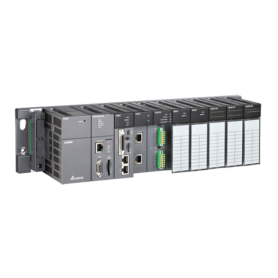
However, the use of the state of the flag is not introduced in this example. 6.1.2 Hardware In this example, the AH500 series CPU module used is AHCPU530-EN, the digital I/O module used is AH16AP11R-5A, and the main backplane used is AHBP04M1-5A. The table below is an I/O allocation table. Type... -
Page 179: Procedure For Creating A Project In Ispsoft
Users can set the parameters such as a range of latched devices and a port number in a PLC. Besides, the users have to configure modules used with an AH500 series CPU module, and set the parameters in these modules. -
Page 180: Hardware Configuration
A H 5 0 0 O p e r a t i o n M a n u a l In the Create a New Project window, type a project name in the Project Name box and a path in the Drive/Path box, select a PLC in the Controller Type drop-down list box, and click OK. -
Page 181: Configuring A Module
C h a p t e r 6 W r i t i n g a P r o g r a m 6.4.1 Configuring a Module In the HWCONFIG window, there is an eight-slot backplane on which a CPU module and a power supply module are installed. -
Page 182: Setting The Parameters In A Cpu Module And A Module
A H 5 0 0 O p e r a t i o n M a n u a l The system automatically assigns devices to a module which is added. If the devices assigned to a module do no conform to what is expected, users can click the Input/Output Device Range cell for the module, click in the cell, and type a device address in the Manual Assignment window. - Page 183 C h a p t e r 6 W r i t i n g a P r o g r a m After the users double-click AH16AP11R-5A, the Parameter Setting window will appear. After the Parameter Setting window is opened, the users can view the information related to the module. The users can select the parameter type at the left side of the window, and then set the parameter in the table at the right side of the window.
-
Page 184: Creating A Program
A H 5 0 0 O p e r a t i o n M a n u a l *. Please refer to chapter 8 for more information about HWCONFIG. 6.5 Creating a Program The following sections will lead users to create a traditional ladder diagram in ISPSoft. The contents of the following sections include creating a POU, editing a traditional diagram, and compiling a program. - Page 185 C h a p t e r 6 W r i t i n g a P r o g r a m (3) After the POU is added, a program editing window will appear in the main working area. Local symbol table Program editing area After the program editing window is opened, the corresponding toolbar will appear in the window.
-
Page 186: Basic Editing─Creating A Contact And A Coil
A H 5 0 0 O p e r a t i o n M a n u a l 6.5.2 Basic Editing─Creating a Contact and a Coil on the toolbar, and then move the mouse cursor to the red frame in network 1. The mouse (1) Click cursor appears as a contact when the mouse cursor is moved to the left side of the red frame, the right side of the red frame, or the bottom of the red frame. - Page 187 C h a p t e r 6 W r i t i n g a P r o g r a m on the toolbar, and move the mouse cursor to the (3) Click the line at the right side of the contact, click red frame.
- Page 188 A H 5 0 0 O p e r a t i o n M a n u a l (5) Click ??? above the contact, type a device address in the box, and press Enter on the keyboard to jump to the next box in the network.
-
Page 189: Basic Editing─Inserting A Network And Typing An Instruction
C h a p t e r 6 W r i t i n g a P r o g r a m Basic Editing─Inserting a Network and Typing an Instruction 6.5.3 on the toolbar is clicked, a network will be under the network selected. After on the toolbar is After clicked, a network will be put above the network selected. - Page 190 A H 5 0 0 O p e r a t i o n M a n u a l (3) Type the IL instruction “OUT Y0.0”, and write the program shown below. Additional remark A contact and a coil can be created by typing simple instructions. Please refer to the description below. (The instructions typed are case-insensitive.) ...
-
Page 191: Basic Editing─Selection Of A Network And Operation
C h a p t e r 6 W r i t i n g a P r o g r a m Basic Editing─Selection of a Network and Operation 6.5.4 Before an object in a network is selected, users have to press Esc on the keyboard, or click on the toolbar. -
Page 192: Basic Editing─Connecting A Contact In Parallel
A H 5 0 0 O p e r a t i o n M a n u a l Item Function Pasting an object under the position selected Paste under (The object will be connected to the position selected in parallel.) Deleting a device, a block, or a network Delete Activate/Inactivate... -
Page 193: Basic Editing─Editing A Comment
C h a p t e r 6 W r i t i n g a P r o g r a m (2) Write the program in network 2 shown below in the way described above. Additional remark After users select a group of contacts, they can connect a contact to the group of contacts in the way described above. -
Page 194: Basic Editing─Inserting An Applied Instruction
A H 5 0 0 O p e r a t i o n M a n u a l (3) Write the program shown below in the way described above. 6.5.7 Basic Editing─Inserting an Applied Instruction Put network 6 under network 5, and then write the program shown below. Users can insert an applied instruction in one of the three ways described below. - Page 195 C h a p t e r 6 W r i t i n g a P r o g r a m Method 2 Unfold the APIs section in the project management area, find the instruction type, and unfold the instruction type section.
- Page 196 A H 5 0 0 O p e r a t i o n M a n u a l After the instruction is inserted successfully, the users can assign a device address to the operand, and write the program shown below. 6.5.8 Basic Editing─Creating a Comparison Contact and Typing a Constant A comparison contact can be inserted not only in one of the three ways described in section 6.5.7, but also by...
-
Page 197: Writing A Program
C h a p t e r 6 W r i t i n g a P r o g r a m Write the program shown below in the way described above. In WPLSoft, a decimal value is preceded by K, and a hexadecimal value is preceded by H. -
Page 198: Checking And Compiling A Program
A H 5 0 0 O p e r a t i o n M a n u a l 6.5.10 Checking and Compiling a Program After users write a program, they can check the syntax of the programming language or compile the program. The syntax and the structure in the present window will be checked after the Check function is enabled. -
Page 199: Testing And Debugging A Program
Make sure that the wiring is correct, and then power the CPU module. (2) Connect the CPU module to the computer through a USB cable. If the USB driver for the AH500 series CPU module has been installed on the computer, Delta PLC will appear in the Device Manager Window, and a port number will be assigned to Delta PLC. - Page 200 A H 5 0 0 O p e r a t i o n M a n u a l (5) Set the parameters in the Driver Properties window, and then click OK. Type a driver name in the Driver Name box. Select USB (Virtual COM) in the Type drop-down list box in the Connection Setup section.
-
Page 201: Downloading A Program And Parameters
C h a p t e r 6 W r i t i n g a P r o g r a m (7) Start ISPSoft, and then click Communication Settings… on the Tools menu. In the Communication Setting window, select the driver which has been created in the Driver drop-down list box, appear, and select 0 in the Station Address drop-down list box, and click OK. - Page 202 A H 5 0 0 O p e r a t i o n M a n u a l (2) The hardware configuration is displayed in the window. Before the hardware configuration is downloaded to the CPU module, users have to make sure that the actual hardware configuration is the same as the hardware configuration in the window.
-
Page 203: Connection Test
C h a p t e r 6 W r i t i n g a P r o g r a m 6.6.3 Connection Test After a program is downloaded to a PLC, users can monitor the execution status of the PLC through ISPSoft. - Page 204 A H 5 0 0 O p e r a t i o n M a n u a l In the online monitoring mode, users can view the present scan time, the communication status, and the status of the PLC in the status bar in ISPSoft. Besides, the present statuses of the devices will be displayed in the original program editing window after the program monitoring function is enabled.
- Page 205 C h a p t e r 6 W r i t i n g a P r o g r a m Item Description Forcing an input contact or output contact ON or OFF Force Forcing several input contacts or output contacts in the tables ON or OFF Force Device List If users want to change the value in a device, they can click the device, right-click the device, click Change Present Value on the context menu, and set a present value in the Enter Present Value window.
- Page 206 A H 5 0 0 O p e r a t i o n M a n u a l However, an input contact can be forced ON or OFF during a test. Users can click an input contact or output contact which will be set, right-click the contact, point to Force on the context menu, and select On (X/Y), Off (X/Y), Release (X/Y), or Release All.
- Page 207 C h a p t e r 6 W r i t i n g a P r o g r a m Method 2 Right-click Device Monitoring Table in the project management area, and click Add. Type a table name in the Add Monitor Table window, and then click OK. An item will be under Device Monitor Table in the project management area.
- Page 208 A H 5 0 0 O p e r a t i o n M a n u a l If the users want to hide certain columns in the monitoring table, they can right-click the monitoring table, point to Set the Fields, and unselect certain items. After an item is unselected, the corresponding column will disappear.
-
Page 209: Setting A Real-Time Clock
C h a p t e r 6 W r i t i n g a P r o g r a m Setting a Real-time Clock After an AH500 series CPU module is connected to a computer, users can set the real-time clock in the CPU module through ISPSoft. - Page 210 A H 5 0 0 O p e r a t i o n M a n u a l MEMO 6 - 3 4...
-
Page 211: Chapter 7 Memory Card
Chapter 7 Memory Card Table of Contents Overview of Memory Cards ................7-2 7.1.1 Appearances of Memory Cards ..............7-2 7.1.2 Specifications for SD Cards ................ 7-2 Using a Memory Card ..................7-3 7.2.1 Formatting a Memory Card ................. 7-3 7.2.2 Write Protect Function of a Memory Card ........... -
Page 212: Overview Of Memory Cards
These types are SD cards, SDHC cards, and SDXC cards. The AH500 basic series CPU modules presently support SD cards up to 2GB and the AH500 advanced series CPU modules presently support SDHC cards up to 32GB. The following is the table of SD card families. -
Page 213: Using A Memory Card
A memory card that users use for the first time may not be formatted. A memory card which is not formatted can not be used in an AH500 series CPU module. Therefore, users need to format the memory card. The file system with which the memory card is formatted is FAT. -
Page 214: Write Protect Function Of A Memory Card
A H 5 0 0 O p e r a t i o n M a n u a l (3) The file system with which the memory card is formatted must be FAT. The other default setting is retained. Click Quick Format, and then click Start. -
Page 215: Installing And Removing A Memory Card
C h a p t e r 7 Me m o r y C a r d 7.3 Installing and Removing a Memory Card 7.3.1 SD Slot in a CPU Module As shown below, the SD slot is in the lower right corner of the front of a CPU module. AHCPU5X0-RS/ AHCPU5X1-RS AHCPU5X0-EN/ AHCPU5X1-EN SD slot... -
Page 216: Contents Of A Memory Card
7.4.2 Folder Structure in a Memory Card The default folder group created by an AH system is shown below. The folder name is AH500. Several subfolders are contained inside the AH500 folder. Related files created by users and the AH system are stored in the subfolders. -
Page 217: Reading/Writing A Memory Card
C h a p t e r 7 Me m o r y C a r d 7.5 Reading/Writing a Memory Card Users can read/write data into/from a memory card to back up and update a system by means of the DIP switch on a CPU module. -
Page 218: Introduction Of Card Utility
The program code, the parameter setting, the hardware configuration, and the network configuration in an AH500 series CPU module or an ISPSoft project can be backed up. The values in the devices in an AH500 series CPU module can also be backed up. Please refer to operation manuals or technical documents for more information about the specifications of the SD cards which can be inserted into AH500 series CPU modules, and the usage of the SD cards. - Page 219 AH500 series CPU module. Users can put a backup file (*.dup) saved in a computer into the AH500 series CPU module connected to the computer, or restore the backup file to an ISPSoft project. If the users choose to restore the backup file to an ISPSoft project, the system will automatically skip the values in the devices and the hardware configuration in the backup file.
-
Page 220: Backup
A H 5 0 0 O p e r a t i o n M a n u a l 7.7 Backup If the backup source/backup destination is an AH500 series CPU module or the memory card inserted in an AH500 series CPU module, users have to make sure that ISPSoft is connected to the AH500 series CPU module normally. - Page 221 After the users select the CPU (Need Connection) option button, they have to decide whether to back up the values in the devices in the AH500 series CPU module which is connected to ISPSoft. Select a backup destination. To backup an ISPSoft project, the backup destination must be a computer.
- Page 222 Even if the users click Cancel to stop ISPSoft from performing the data backup in the process of backing up data in the AH500 series CPU module onto the memory card inserted in the AH500 series CPU module, the AH500 series CPU module will still performs the data backup. The users can turn off the AH500 series CPU module to stop the data backup from being performed.
-
Page 223: Restoration
If the restoration source/restoration destination is an AH500 series CPU module or the memory card inserted in an AH500 series CPU module, users have to make sure that ISPSoft is connected to the AH500 series CPU module normally. Please refer to section 2.4 in ISPSoft User Manual for more information. - Page 224 (3) Select a restoration destination, and then click Next. If the users want to put the backup file selected into the AH500 series CPU module which is connected to ISPSoft, they have to select the CPU (Need Connection) option button. If the restoration source is the memory card inserted in the AH500 series CPU module connected to ISPSoft, the restoration destination must be the AH500 series CPU module.
- Page 225 Execute. If the users click Cancel in the process of restoring data to the AH500 series CPU module, the data will not be completely restored. To prevent the AH500 series CPU module from operating incorrectly, the users have to restore the AH500 series CPU module to the factory setting if they do not perform the data restoration again.
- Page 226 A H 5 0 0 O p e r a t i o n M a n u a l Data restoration Description a. The ID in the backup file must be the same as the ID in the CPU module, otherwise the data restoration will not be performed.
- Page 227 8.1.2.14 Dragging an Extension Rack .............. 8-28 8.1.2.15 Rearranging the Input/Output Devices ..........8-28 Setting the Parameters in an AH500 Series CPU Module ......... 8-29 8.2.1 Opening the PLC Parameter Setting Window ..........8-29 8.2.2 Setting the Basic CPU Parameters ............8-30 8.2.2.1...
- Page 228 8.4.6.4 Monitoring Table ................. 8-68 Setting Interrupts ....................8-69 8.5.1 Program Architectures ................8-69 8.5.2 Tasks Supported by AH500 Series CPU Modules ........8-69 8.5.3 I/O Interrupts ....................8-70 8.5.4 Low Voltage Detection Interrupt ..............8-71 8.5.5 Communication Interrupts ................8-72 8.5.6...
-
Page 229: Hardware Configuration Tool For Ah500 Series Modules─Hwconfig
A H 5 0 0 O p e r a t i o n M a n u a l 8.1 Hardware Configuration Tool for AH500 Series Modules─HWCONFIG HWCONFIG is a built-in hardware configuration tool in ISPSoft. Users can configure racks, set CPU parameters, set module parameters, download/upload parameters, detect a hardware configuration online, and make a diagnosis through HWCONFIG. - Page 230 C h a p t e r 8 H a r d wa r e C o n f i g u r a t i o n If users want to select a rack, they can move a mouse cursor to the extension port on the rack, and click the extension port.
-
Page 231: Configuring A Module
A H 5 0 0 O p e r a t i o n M a n u a l 8.1.2 Configuring a Module 8.1.2.1 Adding a Module Method 1 After users select a module which will be added to the product list, they can drag it to a vacant slot. *. - Page 232 C h a p t e r 8 H a r d wa r e C o n f i g u r a t i o n (2) If the users click a module in the Module Selection window, the specifications for the module will appear in the Specification box.
- Page 233 A H 5 0 0 O p e r a t i o n M a n u a l (2) If the users click a module in the Module Selection window, the specifications for the module will appear in the Specification box. After the users double-click a module in the Module Selection window, the module will be added.
-
Page 234: Assigning Devices To A Module
C h a p t e r 8 H a r d wa r e C o n f i g u r a t i o n 8.1.2.2 Assigning Devices to a Module The data in a module needs to be updated constantly. For example, analog signals received by an analog input module are updated constantly, and converted to data which can be processed by a CPU module. - Page 235 A H 5 0 0 O p e r a t i o n M a n u a l If users want to know functions to which devices assigned correspond, they can double-click the module or the information about the module on the information list to open the Parameter Setting window. *.
- Page 236 C h a p t e r 8 H a r d wa r e C o n f i g u r a t i o n the users can access the module through the data registers. Accessing a module through the data registers is more efficient than accessing the module through the instruction FROM/TO.
- Page 237 A H 5 0 0 O p e r a t i o n M a n u a l Devices that users assign to a module so that the data in the module can be stored can not overlap data registers that the users assign to a module so that the parameters in the module can be stored.
-
Page 238: Editing A Comment
C h a p t e r 8 H a r d wa r e C o n f i g u r a t i o n 8.1.2.3 Editing a Comment After users click the gray area at the top of the system configuration area, they can type a comment about the hardware configuration in the drop-down box that appears. -
Page 239: Deleting A Module
A H 5 0 0 O p e r a t i o n M a n u a l 8.1.2.4 Deleting a Module There are two ways to delete a module which has been configured. (The CPU module and the power supply module can not be deleted.) ... -
Page 240: Searching For/Replacing A Module
C h a p t e r 8 H a r d wa r e C o n f i g u r a t i o n (2) Point to Replace on the context menu, and then click Sam Type or All. ... - Page 241 A H 5 0 0 O p e r a t i o n M a n u a l Click in the Find what box, select a module in the Module Selection window, and double-click the module. The users can also type part of a module model in the Find what box. Finally, click Find. After the search is complete, modules meet the search condition will be listed in the list.
- Page 242 C h a p t e r 8 H a r d wa r e C o n f i g u r a t i o n parameters in the module replaced, the setting of the parameters in the new module will be restored to the default values.
- Page 243 A H 5 0 0 O p e r a t i o n M a n u a l After the setting of the replacement condition is complete, the users can click Replace to replace the module selected with the new module. After the replacement is complete, the search list will be updated, and the next module will be selected automatically.
-
Page 244: Copying/Pasting A Module
C h a p t e r 8 H a r d wa r e C o n f i g u r a t i o n 8.1.2.7 Copying/Pasting a Module There are two ways to copy a module. (The CPU module and the power supply module can not be copied/pasted.) ... - Page 245 A H 5 0 0 O p e r a t i o n M a n u a l Method 2 Click a slot on which a module will be pasted in the system configuration area or on the information list. Click Paste on the Edit menu, or on the toolbar.
-
Page 246: Cutting/Pasting A Module
C h a p t e r 8 H a r d wa r e C o n f i g u r a t i o n 8.1.2.8 Cutting/Pasting a Module There are two ways to cut a module. (The CPU module and the power supply module can not be cut/pasted.) ... -
Page 247: Dragging A Module
A H 5 0 0 O p e r a t i o n M a n u a l Method 2 (1) Click a slot on which a module will be pasted in the system configuration area or on the information list. -
Page 248: Adding An Extension Rack
C h a p t e r 8 H a r d wa r e C o n f i g u r a t i o n 8.1.2.10 Adding an Extension Rack There are two ways to add an extension module. ... -
Page 249: Deleting A Rack
A H 5 0 0 O p e r a t i o n M a n u a l Method 2 Right-click the blank in the system configuration area, click Add on the context menu, and double-click an extension rack which will be added in the Rack Selection window. -
Page 250: Replacing A Rack
C h a p t e r 8 H a r d wa r e C o n f i g u r a t i o n (2) Click Delete on the Edit menu, click on the toolbar, or press Delete on the keyboard. ... -
Page 251: Cutting/Copying/Pasting An Extension Rack
A H 5 0 0 O p e r a t i o n M a n u a l (2) Double-click a rack in the Rack Selection window. Additional remark If the number of slots on the new rack is less than the number of slots on the original rack, the modules on the original rack which can not be installed on the new rack will be deleted automatically. - Page 252 C h a p t e r 8 H a r d wa r e C o n f i g u r a t i o n Method 2 Click the left side of a rack which will be copied or cut. If users want to copy the rack, they can click Copy on the Edit menu, or click on the toolbar.
- Page 253 A H 5 0 0 O p e r a t i o n M a n u a l Method 2 Click the blank or a present rack in the system configuration area, and then click Paste on the Edit menu, on the toolbar.
-
Page 254: Dragging An Extension Rack
C h a p t e r 8 H a r d wa r e C o n f i g u r a t i o n 8.1.2.14 Dragging an Extension Rack Drag an extension rack to another extension rack when the left mouse button is held. The two extension racks will be interchanged. -
Page 255: Setting The Parameters In An Ah500 Series Cpu Module
A H 5 0 0 O p e r a t i o n M a n u a l 8.2 Setting the Parameters in an AH500 Series CPU Module The following software snapshots are from AH500 basic series CPU modules (AHCPU500/510/520/530). 8.2.1 Opening the PLC Parameter Setting Window After users double-click the CPU module in the system configuration area, the PLC Parameter Setting window will appear. -
Page 256: Setting The Basic Cpu Parameters
C h a p t e r 8 H a r d wa r e C o n f i g u r a t i o n 8.2.2 Setting the Basic CPU Parameters 8.2.2.1 CPU: Name After users click the CPU tab at the top of the window, and the Name tab at the bottom of the window, they can type 31 characters at most in the Name box, and 60 characters at most in the Comment box. -
Page 257: Cpu: System
A H 5 0 0 O p e r a t i o n M a n u a l 8.2.2.2 CPU: System After users click the CPU tab at the top of the window, and the System tab at the bottom of the window, they can set the parameters in the CPU module. - Page 258 Interval Interrupt Time An AH500 series CPU module provides four interrupts. Users can set intervals of triggering the interrupts. In ISPSoft, a timed interrupt is created through a task and a POU. Please refer to chapter 5 in ISPSoft User Manual for more information.
- Page 259 Twenty error logs at most can be stored in an AH500 series CPU module. If there are more than twenty error logs, the oldest error log will be overwritten by the latest error log. However, if the PLC and PLC CARD option button is selected, and there are more than twenty error logs, the oldest error log will be backed up in the memory card before the oldest error log is overwritten.
-
Page 260: Cpu: Latched Device Range
C h a p t e r 8 H a r d wa r e C o n f i g u r a t i o n *. The parameters set in HWCONFIG must be downloaded to the CPU module so that they can take effect. (Please refer to section 8.2.6 or section 8.4.4 for more information.) 8.2.2.3 CPU: Latched Device Range... - Page 261 A H 5 0 0 O p e r a t i o n M a n u a l (2) Please select values in the boxes. The value in the left box is a start address, and the value in the right box is an end address.
-
Page 262: Com Port
C h a p t e r 8 H a r d wa r e C o n f i g u r a t i o n In the setting page below, the range of latched data registers is D0~D32768. The number of latched data registers is 32769. -
Page 263: Ethernet─Basic
A H 5 0 0 O p e r a t i o n M a n u a l If the sending of a command fails, the CPU module will retry the sending of the command. Users can set the number of times the sending of a command is retired in this box. -
Page 264: Ethernet─Advance
C h a p t e r 8 H a r d wa r e C o n f i g u r a t i o n If AH5x1 series is used, you can use DNS server to obtain DNS addresses automatically or manually. - Page 265 A H 5 0 0 O p e r a t i o n M a n u a l Enable IP Address Filter If the Enable IP Address Filter checkbox is selected, devices whose IP addresses are listed in the table will be allowed to communicate with the CPU module, and the CPU module will discard data packets sent from devices whose IP addresses are not listed in the table.
-
Page 266: Ethernet─Advance: Ntp
C h a p t e r 8 H a r d wa r e C o n f i g u r a t i o n *1. The parameters set in HWCONFIG must be downloaded to the CPU module so that they can take effect. (Please refer to section 8.2.6 or section 8.4.4 for more information.) *2. -
Page 267: Ethernet─Advance: Email
A H 5 0 0 O p e r a t i o n M a n u a l Users can set the IP address of an NTP server. The CPU module corrects the time inside itself by connecting to the server periodically. -
Page 268: Ethernet─Advance: Email Trigger
C h a p t e r 8 H a r d wa r e C o n f i g u r a t i o n Local Email Address: Users can set the address of an actual sender. A local email address is composed of 64 characters at most. - Page 269 A H 5 0 0 O p e r a t i o n M a n u a l (1) Type a trigger name and an interval of triggering the sending of an email in the Trigger Setting section. ...
- Page 270 C h a p t e r 8 H a r d wa r e C o n f i g u r a t i o n Periodic Timer An email is sent periodically. How often an email is sent depends on the interval typed in the Trigger Interval box in the Trigger Setting section.
- Page 271 A H 5 0 0 O p e r a t i o n M a n u a l (4) Select the None option button, the File option button, or the PLC Device option button in the Attachment section. If users want to set an attachment, they have to make sure of the maximum size of an email which the CPU module allows.
-
Page 272: Ethernet─Advance: Email And Trigger Configuration
C h a p t e r 8 H a r d wa r e C o n f i g u r a t i o n 8.2.5.5 Ethernet─Advance: Email and Trigger Configuration After users click the Ethernet─Advance tab at the top of the window, and the Email and Trigger Configuration tab at the bottom of the window, they can set the relation between triggers for the sending of emails and receivers. -
Page 273: Ethernet─Advance: Socket
Sockets will not be introduced here. Please refer to related documents or manuals for more information about sockets. An AH500 system supports the transmission of data between the CPU module and other CPU modules or devices by means of the creation of sockets, and supports TCP and UDP. Users can set eight TCP connections and eight UDP connections. - Page 274 C h a p t e r 8 H a r d wa r e C o n f i g u r a t i o n Users can set a remote IP address. Users can set a communication port used by the remote device for this TCP connection. The port number must be in the range of 0 to 65535.
-
Page 275: Ethernet─Advance: Web
A H 5 0 0 O p e r a t i o n M a n u a l 8.2.5.7 Ethernet─Advance: Web After users click the Ethernet─Advance tab at the top of the window, and the Web tab at the bottom of the window, they can enable the built-in web monitoring function of the CPU module. -
Page 276: Saving And Downloading/Uploading The Plc Parameters
C h a p t e r 8 H a r d wa r e C o n f i g u r a t i o n 8.2.6 Saving and Downloading/Uploading the PLC Parameters After the setting of the PLC parameters is complete, users can click OK to apply the parameters. However, the parameters are still not saved as a file. -
Page 277: Setting The Parameters In An Ah500 Series Module
A H 5 0 0 O p e r a t i o n M a n u a l 8.3 Setting the Parameters in an AH500 Series Module 8.3.1 Managing the Version of a Module The functions of a module or the parameters in the module vary with the versions of the module. In HWCONFIG, the functions of the modules and the parameters in the modules are defined in a document called MDS. -
Page 278: Setting The Parameters In A Module
C h a p t e r 8 H a r d wa r e C o n f i g u r a t i o n Click in the Module Name box, select a module model in the Module Selection window, and double-click the module model. - Page 279 The parameters are set according to the functions supported by the module. Before users set the parameters, they have to refer to AH500 Module Manual for more information. To prevent damage to the system or staff, the users have to make sure of the effect that the parameters which are set have on the module and the whole system.
- Page 280 C h a p t e r 8 H a r d wa r e C o n f i g u r a t i o n Users can select a parameter type at the left side of the window, and then set the parameters in the table at the right side of the window.
- Page 281 A H 5 0 0 O p e r a t i o n M a n u a l which has been assigned to the module can not be used. If users want to delete the data register address ess window in the same way, and delete in the Address cell for a parameter, they can open the Addr the data register address in the window.
-
Page 282: Exporting And Importing The Parameters In A Module
C h a p t e r 8 H a r d wa r e C o n f i g u r a t i o n , the values of the After Default in the lower left corner of the Parameter Setting window is clicked parameters in the module will be restored to the default values. -
Page 283: Setting The Parameters In An Intelligent Module
8.3.4 Setting the Parameters in an Intelligent Module Delta Electronics, Inc. provides the exclusive configuration tools for some modules. Through the software, the modules can be configured further, and the parameters in the modules can be set further. Some of the configuration tools can be opened through HWCONFIG. -
Page 284: Management Of The Parameters In Ah500 Series Hardware And Online Diagnosis
C h a p t e r 8 H a r d wa r e C o n f i g u r a t i o n 8.4 Management of the Parameters in AH500 Series Hardware and Online Diagnosis 8.4.1 Saving and Printing a Hardware Configuration... -
Page 285: Purchase Order
A H 5 0 0 O p e r a t i o n M a n u a l 8.4.2 Purchase Order After a hardware configuration is complete, users can click PO List on the Option menu. The system will collect the hardware which are configured, and list it in a list. -
Page 286: Rack Information List
C h a p t e r 8 H a r d wa r e C o n f i g u r a t i o n 8.4.3 Rack Information List After a hardware configuration is complete, users can click Rack Information List on the File menu. The users can view the configuration in the Rack Information List window. -
Page 287: Downloading/Uploading The System Parameters
A H 5 0 0 O p e r a t i o n M a n u a l 8.4.4 Downloading/Uploading the System Parameters The parameters set in HWCONFIG must be downloaded to the CPU module so that they can take effect. Owing to the fact that HWCONFIG adopts the communication setting in ISPSoft, users have to make sure that ISPSoft is connected to the CPU module normally before the parameters are downloaded/uploaded. -
Page 288: I/O Scan
C h a p t e r 8 H a r d wa r e C o n f i g u r a t i o n 8.4.5 I/O Scan Users can configure modules in the way mentioned above. If users have gotten related hardware, they can install the hardware, click I/O Scan in HWCONFIG, and scan the actual hardware configuration through communication. -
Page 289: Online Diagnosis
A H 5 0 0 O p e r a t i o n M a n u a l The parameters in the hardware shown below are downloaded to the CPU module first. The parameter in AH16AN01R-5A (installed in slot 1) is as follows. Then, AH04HC-5A installed in slot 2 is removed from the actual backplane. -
Page 290: Online Mode
C h a p t e r 8 H a r d wa r e C o n f i g u r a t i o n 8.4.6.1 Online Mode (1) After users click Online Mode on the Option menu, or on the toolbar, the hardware configuration will be in the online mode. -
Page 291: Module Information And Diagnosis
A H 5 0 0 O p e r a t i o n M a n u a l 8.4.6.2 Module Information and Diagnosis If the hardware configuration is in the online mode, users can right-click the CPU module or a module, and click Module Information on the context menu. -
Page 292: Changing The Status Of A Module Online
C h a p t e r 8 H a r d wa r e C o n f i g u r a t i o n 8.4.6.3 Changing the Status of a Module Online If the hardware configuration is in the online mode, users can change the status of a module, carry out a simple test. - Page 293 A H 5 0 0 O p e r a t i o n M a n u a l Changing the values of the parameters in a module If a module is assigned data registers, users can change the values in the data registers after the hardware configuration enters the online mode.
-
Page 294: Monitoring Table
C h a p t e r 8 H a r d wa r e C o n f i g u r a t i o n 8.4.6.4 Monitoring Table If the hardware configuration is in the online mode, users can view the values in the data registers in the Monitor Table window after they click Monitor Table on the Option menu. -
Page 295: Setting Interrupts
ISPSoft User Manual for more information about creating interrupts, and writing programs. 8.5.2 Tasks Supported by AH500 Series CPU Modules The number of interrupts supported by an AH500 series CPU module is 288. There are mainly two types of tasks. -
Page 296: I/O Interrupts
Task Description section. If the Active checkbox is unselected, the cyclic task will not be executed until it is activated by the instruction TKON in the POU assigned to another cyclic task. Please refer to AH500 Programming Manual for more information about the instructions TKON and TKOFF. - Page 297 A H 5 0 0 O p e r a t i o n M a n u a l (2) After the users click CH1~4 comparison value setting, they can type comparison values in the Initial cells. (3) After the users click CH1~4 number of interrupt setting, they can type interrupt numbers in the Initial cells.
-
Page 298: Communication Interrupts
A communication interrupt can be used as the instruction RS, that is, the reception of a specific character triggers a communication interrupt. A communication interrupt can also be used as a general interrupt. Please refer to AH500 Programming Manual for more information about the instruction RS. COM1: I32 COM2: I33 8.5.6 External Interrupts... -
Page 299: Timer Interrupts
A H 5 0 0 O p e r a t i o n M a n u a l Users can not set two different interrupt conditions for one interrupt number. For example, if I220 is used by a network module, it can not be used by an analog input/output module. - Page 300 C h a p t e r 8 H a r d wa r e C o n f i g u r a t i o n MEMO 8 - 7 4...
-
Page 301: Chapter 9 Network Configuration
Chapter 9 Network Configuration (Applicable for AHCPU5X0 Models) Table of Contents Network Configuration Tool─NWCONFIG ............9-2 9.1.1 Introduction of NWCONFIG ................. 9-2 9.1.2 Basic Knowledge ..................9-3 9.1.3 Communication Setting in NWCONFIG ............9-4 9.1.3.1 Connection Mechanism in NWCONFIG ..........9-5 9.1.3.2 Setting Communication Parameters ............ -
Page 302: Network Configuration Tool─Nwconfig
A H 5 0 0 O p e r a t i o n M a n u a l 9.1 Network Configuration Tool─NWCONFIG 9.1.1 Introduction of NWCONFIG NWCONFIG is the network configuration tool provided by ISPSoft. Users can configure the network in a project and set up a mechanism for data exchange through NWCONGIF. -
Page 303: Basic Knowledge
PLC name of the device. Please refer to section 8.2.2.1 for more information. However, the PLC name of a device which is not an AH500 series CPU module is like a comment on the device. It has little significance. -
Page 304: Communication Setting In Nwconfig
PLCs perform data exchange according to the start mode selected when the PLCs run. Besides, only AH500 series CPU modules support Ether Links. An Ether Link is not a master/slave model. It allows a node to send reading commands which ask for data to other nodes. -
Page 305: Connection Mechanism In Nwconfig
C h a p t e r 9 N e t w o r k C o n f i g u r a t i o n 9.1.3.1 Connection Mechanism in NWCONFIG In the networks created in NWCONFIG, users can download parameters to a single node or multiple nodes, upload parameters from a single node or multiple nodes, and monitor a single node or multiple nodes. -
Page 306: Setting Communication Parameters
NWCONFIG can also carries out communication through routing. Routing is a function provided by AH500 series CPU modules. It directs packet forwarding. Packet forwarding is the relaying of packets from their source toward their destination through intermediate nodes. In the figure below, the device which actually connects to the computer is AH-01. -
Page 307: Workflow
C h a p t e r 9 N e t w o r k C o n f i g u r a t i o n (4) Select a driver in the Driver Name drop-down list box. If the users want to download parameters to a single device, upload parameters from a single device, or monitor a single device, they have to select a driver which can connect to the device specified. - Page 308 ISPSoft. Please refer to section 2.2 in ISPSoft User Manual for more information. (3) If there are projects for AH500 series CPU modules, the users have to open the HWCONFIG windows in the projects, and complete hardware configurations. The users have to configure modules, set the parameters in network modules, gives names to the CPU modules, set ports, and set Ethernet ports.
- Page 309 C h a p t e r 9 N e t w o r k C o n f i g u r a t i o n 9 - 9...
- Page 310 A H 5 0 0 O p e r a t i o n M a n u a l (4) Complete a network configuration in NWCONFIG. (5) Create a mechanism for data exchange performed by means of a PLC Link or an Ether Link. A PLC Link and an Ether Link operate independently.
- Page 311 NWCONFIG to the PLCs. If the devices in the networks designed include DVP series PLCs or devices which are not AH500 series CPU modules, the users have to set the communication parameters in these DVP series PLCs or devices which are not AH500 series CPU modules.
-
Page 312: Creating A Network Architecture
NWCONFIG window. If the devices deployed in the working area include AH500 series CPU modules, the modules connected to the CPU modules, the parameters in the CPU modules, and the parameters in the modules connected to the CPU modules will be displayed according to the setting in HWCONFIG. - Page 313 The users can add network modules to the working area. However, if the devices deployed in the working area include AH500 series CPU modules for which projects are created, the users can not connect network modules to the CPU modules. If the users want to connect network modules to the CPU modules, they have to close the NWCONFIG window, configure the network modules in HWCONFIG, and save the setting in HWCONFIG.
- Page 314 A H 5 0 0 O p e r a t i o n M a n u a l There are two ways to add a network module to the working area. Method 1 Select a network module on the device list, and then drag it to a PLC in the working area. If the PLC does not support the network module selected, the mouse cursor becomes An AH10EN series module can only be put on a main backplane.
-
Page 315: Connecting To A Network
C h a p t e r 9 N e t w o r k C o n f i g u r a t i o n Method 2 Select a PLC or a rack in the working area, and then double-click a network module on the device list. After the users add a network module to a node, the slot in which the network module is installed, and the backplane on which the network module is installed may be different from the actual slot in which the network module is installed, and the actual backplane on which the network module is installed. - Page 316 A H 5 0 0 O p e r a t i o n M a n u a l Method 2 Click the Edit menu, point to Add a Network, and click Ethernet or RS-485. Method 3 Right-click the blank in the working area, point to Add a Network on the context menu, and click Ethernet or RS-485.
- Page 317 C h a p t e r 9 N e t w o r k C o n f i g u r a t i o n There are several ways to connect the nodes in the working area to networks. ...
- Page 318 A H 5 0 0 O p e r a t i o n M a n u a l (2) After the users click Connect Devices on the Edit menu, or on the toolbar, the system will connect the devices clicked to the network clicked. Additional remark (a) If the objects selected do not conform to the two principles listed above, the system will not connect the devices selected to the network selected, and a warning message will appear.
- Page 319 C h a p t e r 9 N e t w o r k C o n f i g u r a t i o n (2) After the users click Connect Devices on the Edit menu, or on the toolbar, the system will connect the devices clicked to the new network added.
-
Page 320: Adjusting Or Deleting Devices Or Networks
A H 5 0 0 O p e r a t i o n M a n u a l 9.2.3 Adjusting or Deleting Devices or Networks Adjusting the order in which the nodes in the working area are arranged Users can change the order in which the nodes in the working area are arranged by dragging a node to a different position. - Page 321 C h a p t e r 9 N e t w o r k C o n f i g u r a t i o n Adjusting a connection If users press the left mouse button while the mouse cursor hovers over a connection point which connects a network and a port, a small picture representing a trash can and a dotted line will appear.
- Page 322 A H 5 0 0 O p e r a t i o n M a n u a l Deleting a single network by means of a context menu After users right-click a network, and click Delete the Network on the context menu, the network and the lines connected to the network will disappear.
-
Page 323: Setting The Attributes Of A Node/Network
C h a p t e r 9 N e t w o r k C o n f i g u r a t i o n 9.2.4 Setting the Attributes of a Node/Network After users deploy the nodes in the NWCONFIG window, the information about the nodes will put above the nodes. - Page 324 In the Device Information window, there are two tabs. The page displayed in the window depends on the device selected. If the device selected is the AH500 series CPU module for which a project is created, or a module connected to the AH500 series CPU module for which a project is created, most boxes in the Device...
- Page 325 C h a p t e r 9 N e t w o r k C o n f i g u r a t i o n Information window are gray. The attributes of the device can only be modified by means of HWCONFIG. If the device selected is a DVP series PLC, a device which is added to the working area, the users can set the attributes of the device.
- Page 326 A H 5 0 0 O p e r a t i o n M a n u a l Setting the attributes of a network After users double-click a network, the Network Information window will appear. The users can also open the Network Information window by right-clicking the network, and clicking Network Information on the context menu.
-
Page 327: Hiding/Displaying Devices Or Networks
C h a p t e r 9 N e t w o r k C o n f i g u r a t i o n 9.2.5 Hiding/Displaying Devices or Networks Users can hide/display devices or networks in the working area. The number of devices visible and the total number of devices are displayed in the status bar. - Page 328 A H 5 0 0 O p e r a t i o n M a n u a l Hiding a network and the devices connected to the network After users unselect the Visible checkbox in the Network Information box, the network and the devices connected to the network will become invisible, but the other devices connected to the other networks will still be displayed, ...
- Page 329 C h a p t e r 9 N e t w o r k C o n f i g u r a t i o n Select networks which will be displayed in the Networks section in the Devices & Networks Visible Settings window.
-
Page 330: Correct Network Architecture
A H 5 0 0 O p e r a t i o n M a n u a l 9.2.6 Correct Network Architecture After users click Check Routing Information on the Edit menu, or on the toolbar, the system will check whether the network architecture the users create is correct, and the check result will be displayed in the message display area. - Page 331 C h a p t e r 9 N e t w o r k C o n f i g u r a t i o n Node number In principle, the node number assigned to a node in a network can not be the same as the node number assigned to another node in the network.
- Page 332 A H 5 0 0 O p e r a t i o n M a n u a l RS-485 station address In principle, the RS-485 station address of a port in a network can not be the same as the RS-485 station address of another port in the network.
-
Page 333: Downloading Routing Tables
Single node The users have to select a node in the working area. Only AH500 series CPU modules support routing. If the users select a device which is not an AH500 series CPU module, a routing table can not be downloaded to the device. -
Page 334: Testing Routing
A H 5 0 0 O p e r a t i o n M a n u a l Select a Driver window uses must be Ethernet. Please refer to section 9.1.3 for more information. After the users click Download to PLC on the PLC menu, or on the toolbar, the Optional Download window will appear. - Page 335 C h a p t e r 9 N e t w o r k C o n f i g u r a t i o n (2) After the users select the destination device toward which packets are relayed, they have to click the toolbar, or Routing Detect on the PLC menu.
-
Page 336: Managing And Applying Nwconfig
NWCONFIG. If AH500 series CPU modules or AH500 series modules are used, the users have to make sure that the parameters in the AH500 series CPU modules in HWCONFIG or the parameters in the AH500 series modules in HWCONFIG are set correctly, and downloaded to the AH500 series CPU modules or the AH500 series modules successfully. -
Page 337: Downloading Parameters
C h a p t e r 9 N e t w o r k C o n f i g u r a t i o n After the users click Print Preview on the File menu, or on the toolbar, the system will automatically open the Print Preview window, and the network framework that the users create in NWCONFIG will be displayed in the Print Preview window. -
Page 338: Description Of Downloading Parameters
A H 5 0 0 O p e r a t i o n M a n u a l parameters are downloaded to the node. 9.3.2.2 Description of Downloading Parameters If the users want to download parameters, the Routing Mode checkbox in the Select a Driver window must be unselected. -
Page 339: Using Routing In Ispsoft
ISPSoft through routing. If the users want to use routing in ISPSoft, the devices used must be AH500 series CPU modules. In the figure below, the PLC which actually connects to the computer is AH-01. AH-03 can be monitored through routing. - Page 340 A H 5 0 0 O p e r a t i o n M a n u a l (2) Click the Tools menu, and then click Communication Settings…. (3) In the Communication Setting window, the users have to select the Routing Mode checkbox, and select a device in the First Station drop-down list box.
- Page 341 Chapter 10 Operating Principle of the CPU Module Table of Contents 10.1 Operation of the CPU Module ............... 10-2 10.1.1 Procedure ..................... 10-2 10.1.2 I/O Refreshing and Communication Service .......... 10-3 10.2 Operating Modes of the CPU Module ............10-3 10.2.1 Operating Modes ...................
- Page 342 A H 5 0 0 O p e r a t i o n M a n u a l 10.1 Operation of the CPU Module 10.1.1 Procedure The operation of the CPU module is described below. The CPU module is supplied with power. The system enables the initialization.
- Page 343 C h a p t e r 1 0 O p e r a t i n g P r i n c i p l e o f t h e C P U M o d u l e 10.1.2 I/O Refreshing and Communication Service ...
- Page 344 A H 5 0 0 O p e r a t i o n M a n u a l Relation between the operating modes and the tasks Mode Loop task Interrupt task The execution of the interrupt STOP The execution of the loop task stops.
- Page 345 Chapter 11 Convenient Functions Table of Contents 11.1 PLC Link (for AHCPU5X0 models) ..............11-2 11.1.1 Introduction of a PLC Link ..............11-2 11.1.2 Constructing a PLC Link in NWCONFIG in ISPSoft ....... 11-2 11.1.2.1 Opening the PLC Link Table Editor Window ........11-3 11.1.2.2 Designating a Port as a Master Station (Step 1) ......
-
Page 346: Plc Link (For Ahcpu5X0 Models)
A H 5 0 0 O p e r a t i o n M a n u a l 11.1 PLC Link (for AHCPU5X0 models) This function is applicable for AH500 basic CPU module series (AHCPU500/510/520/530). 11.1.1 Introduction of a PLC Link A PLC Link is a network mechanism for data exchange performed through an RS-485 cable. -
Page 347: Opening The Plc Link Table Editor Window
C h a p t e r 11 C o n v e n i e n t F u n c t i o n s 11.1.2.1 Opening the PLC Link Table Editor Window Before creating a PLC Link, users have to make sure that all the network setting is correct. Please use one of the methods described below. -
Page 348: Designating A Port As A Master Station (Step 1)
Designating a Port as a Master Station (Step 1) Only an AH500 series CPU module, an AH500 series module, a DVP series PLC, or a DVP series module can be designated as the master station. Not all ports of a PLC or a module can be designated as the master station, and therefore users have to read the usage of the PLC or the module before they designate a port as the master station. - Page 349 C h a p t e r 11 C o n v e n i e n t F u n c t i o n s (1) Select a port of a node in the Master Device drop-down list box. Only the ports which can be designated as master stations are listed.
-
Page 350: Setting Communication Parameters (Step 2)
Please refer to manuals for more information. If an AH500 series CPU module or an AH500 series module is designated as a master station, the 450 words (AH Only) option button in the Transfer Capacity Mode section can be selected. Only AH500 series CPU modules allow 450-word data to be exchanged. -
Page 351: Creating A Data Exchange Table (Step 3)
C h a p t e r 11 C o n v e n i e n t F u n c t i o n s DVP series PLCs. Synchronic R/W Generally speaking, a master station sends a writing command and a reading command to a slave station separately. - Page 352 A H 5 0 0 O p e r a t i o n M a n u a l Column Description The data exchange groups in the data exchange table in the PLC Link Table Serial Editor window are numbered. Users can set 16 data exchange groups or 32 Number (#) data exchange groups, depending on the model selected.
- Page 353 C h a p t e r 11 C o n v e n i e n t F u n c t i o n s Serial Description number The master station reads the data in 16#1000~16#1018 in the slave station whose station number is 3, and stores the data in D3400~D3424 in itself.
- Page 354 Related setting Description The 450 words Only AH500 series CPU modules allow 450-word data to be exchanged. As a (AH Only) option result, if the 450 words (AH Only) option button in the Transfer Capacity Mode button in the...
- Page 355 C h a p t e r 11 C o n v e n i e n t F u n c t i o n s Related setting Description The 16 words If the master station selected is a DVP series PLC, the 16 words option button in option button in the the Transfer Capacity Mode section can be selected.
- Page 356 Enable option button in the Linked Status section. If the data uploaded from the master station which is an AH500 series CPU module is not consistent with the network created in NWCONFIG, the device types shown in the data exchange table in the PLC Link Table Editor window will still be consistent with the device names shown in the working area in NWCONFIG, the incorrect device types will be in red, and “Disabled”...
- Page 357 C h a p t e r 11 C o n v e n i e n t F u n c t i o n s The present network created in NWCONFIG is shown below. The slave station to which the station address 1 is assigned is a DVP-SV2 series PLC.
-
Page 358: Monitoring A Plc Link
A H 5 0 0 O p e r a t i o n M a n u a l Item Description After the users make sure that the setting of a PLC Link is correct, they can Monitor and download the setting to the master station. - Page 359 C h a p t e r 11 C o n v e n i e n t F u n c t i o n s displayed in this area. The users can also edit registers online in this area. ...
- Page 360 Besides, the PLC Link error flags in an AH500 series CPU module are slightly different from the PLC Link error flags in a DVP series PLC, and therefore the small picture representing an AH500 series CPU module is different from the small picture representing a DVP series PLC.
- Page 361 C h a p t e r 11 C o n v e n i e n t F u n c t i o n s Read Register on the context menu. Write Register: The data written into the slave station specified is stored in registers in the master station.
-
Page 362: Important Points About Constructing A Plc Link
A H 5 0 0 O p e r a t i o n M a n u a l If the users double-click the Value cell for a device, or click Edit Value on the context menu after they right-click the Value cell, they can type a value in the Enter Value window. - Page 363 C h a p t e r 11 C o n v e n i e n t F u n c t i o n s When a PLC Link is executed, the master station sends reading/writing commands to the slave stations according to the data exchange table created.
-
Page 364: Executing A Plc Link Through The Program In Ispsoft
D0. If the AH500 MODBUS communication protocol is used, the start address in the master station is an AH500 MODBUS device address. If the standard MODBUS communication protocol is used, the start address in the master station is a MODBUS device address. - Page 365 Additional remark: A PLC Link can be executed only if the AH500 series CPU modules runs. If the number of data read from a slave station and the number of data written into a slave station are 0, no data exchange is performed. If a PLC Link is executed, the parameters related to the PLC link can not be modified.
- Page 366 16#0001 Additional remark: There are a variety of Delta PLCs. Users can construct a PLC Link by connecting AH500 series CPU modules to DVP series PLCs, and other models. Consequently, there are limitations on the devices which can be used, the data exchange which can be performed, and the number of data which can be exchanged.
- Page 367 1600 contacts at most. If an AH500 series CPU module is a master station, DVP series PLCs can function as slave stations. DVP series PLCs can read data and write data simultaneously.
- Page 368 DVP protocol series PLC *1. If the AH500 MODBUS communication protocol is used, users can use relays, data registers, and link registers. *2. If the standard MODBUS communication protocol is used, devices which are not data registers can not be involved in synchronous data exchange.
-
Page 369: Setting A Plc Link
C h a p t e r 11 C o n v e n i e n t F u n c t i o n s 11.1.3.2 Setting a PLC Link The process of setting a PLC Link is described below. Step 1: Setting the parameters related to a PLC Link Set the special data registers and the special auxiliary relays which are described in section 11.1.3.1. - Page 370 A H 5 0 0 O p e r a t i o n M a n u a l Flowchart: Setting the parameters related to a PLC Link Manually Automatic ally Ass igning slav e RST SM1595 S ET S M1595 station address es manually/automaticall y SM1595...
- Page 371 C h a p t e r 11 C o n v e n i e n t F u n c t i o n s addresses starting from D300 in slave station 1 is read into the device address starting from D100 in the master station.
- Page 372 A H 5 0 0 O p e r a t i o n M a n u a l M1 to ON, and then set values for D0~D9. Users can check whether data exchange is preformed correctly by comparing the data in D0~D9 with the data in D100~D109. Method 2: If users write a program, they will spend much time setting special data registers and special auxiliary relays.
- Page 373 C h a p t e r 11 C o n v e n i e n t F u n c t i o n s Step 2: The users have to click until the system lead them to the third step. A.
- Page 374 A H 5 0 0 O p e r a t i o n M a n u a l Step 3: will become ∥. A. After the users click in the Linked Machines Status window, B. After the users right-click (1) Addr,: 2, they have to click Write Register on the context menu. C.
-
Page 375: Related Special Auxiliary Relays And Special Data Registers
ON: The number of times the master station polls the slave stations is incorrect. Selecting a communication protocol Standard MODBUS communication OFF: Standard MODBUS communication SM1593 protocol/AH500 MODBUS protocol (Default) communication protocol ON: AH500 MODBUS communication protocol 11 - 3 1... - Page 376 A H 5 0 0 O p e r a t i o n M a n u a l Device Name Description The master station will detect the slave stations automatically only if the execution of the PLC Link stops. Detecting the slave stations OFF: The master station finishes detecting SM1594...
-
Page 377: Ether Link (For Ahcpu5X0 Models)
If the parameters which are set are downloaded to the PLCs in the network, the systems of the PLCs perform data exchange according to the start mode selected when the PLCs run. The users do not have to write a redundant program. Besides, only AH500 series CPU modules support Ether Links. -
Page 378: General Specifications And Functions
A H 5 0 0 O p e r a t i o n M a n u a l a PLC Link. Besides, all the nodes in an Ethernet network can send reading commands through TCP/IP, and the system automatically manages the transmission of packets through TCP/IP. Compared with a PLC Link, an Ether Link is more efficient. -
Page 379: Steps Of Constructing An Ether Link
C h a p t e r 11 C o n v e n i e n t F u n c t i o n s Flexible control There are three start modes. (1) Always Run: When the PLC runs, data exchange is performed. (2) Always Stop: During the operation of the PLC, no data exchange is performed. -
Page 380: Constructing An Ether Link In Nwconfig In Ispsoft
A H 5 0 0 O p e r a t i o n M a n u a l 11.2.2 Constructing an Ether Link in NWCONFIG in ISPSoft 11.2.2.1 Constructing an Ether Link Please refer to the example below for more information. If users want to create an Ether Link shown below, they have to create a data exchange table for the two data request nodes AH-01 and AH-02. - Page 381 C h a p t e r 11 C o n v e n i e n t F u n c t i o n s Method 2 Double-click a network. Method 3 Right-click a network, and then click Construct Ether Link on the context menu. The Ether Link Configuration window is shown below.
-
Page 382: Creating And Managing A Data Exchange Table
The information is composed of a node number, a PLC name, and a model name. The IP address assigned to AH500 series CPU module is 192.168.1.2. The start mode of the Ether Link constructed is Always Run. ... - Page 383 C h a p t e r 11 C o n v e n i e n t F u n c t i o n s The steps of setting a data exchange group are as follows. (1) Select a node number in the # cell for the data demanding node. After the users select a node number, the PLC name corresponds to the node number will be appear in the Device Name cell for the node number.
- Page 384 A H 5 0 0 O p e r a t i o n M a n u a l Range cell for a data demanding node can not overlap the device range in the Range cell for another data demanding node whereas the device range in the Range cell for a data supply node can overlap the device range in the Range cell for another data supply node.
-
Page 385: Node List And Display Area
C h a p t e r 11 C o n v e n i e n t F u n c t i o n s After the users create a data exchange table, they can click Check Table Correctness on the Edit menu or on the toolbar if they wan to check the data set in the table. - Page 386 A H 5 0 0 O p e r a t i o n M a n u a l In the figure below, the dotted frame indicates that node 1 on the node list is selected, and the gray ground indicates that node 2 is a data supply node.
-
Page 387: Start Mode Of An Ether Link
C h a p t e r 11 C o n v e n i e n t F u n c t i o n s and set the other cells. 11.2.2.5 Start Mode of an Ether Link There are three start modes. Please refer to the table below for more information. Start mode Description Always Stop... - Page 388 A H 5 0 0 O p e r a t i o n M a n u a l There are three ways to set the start mode of a node. Method 1 Right-click CPU information or module information, and then click Set Startup Mode on the context menu. ...
-
Page 389: Downloading The Parameters Related To An Ether Link
C h a p t e r 11 C o n v e n i e n t F u n c t i o n s After the users use one of the methods described above, the Starting Mode Setup window will appear. The page displayed in the window varies with the information selected. - Page 390 A H 5 0 0 O p e r a t i o n M a n u a l Method 2 Select a data demanding node, right-click the data demanding node, and click Download (Single PLC) on the context menu. ...
-
Page 391: Uploading The Parameters Related To An Ether Link
C h a p t e r 11 C o n v e n i e n t F u n c t i o n s Additional remark If the parameters set include a node which does not demand any data, the node will not demand any data through the network specified after the parameters are downloaded to multiple nodes. -
Page 392: Deleting Asynchronous Device
A H 5 0 0 O p e r a t i o n M a n u a l The parameters related to an Ether Link in all the nodes are uploaded. Before the users upload the related parameters, they have to make sure that all the PLCs and all the modules are connected to an Ethernet network, and can connect to NWCONFIG through Ethernet. -
Page 393: Enabling/Disabling The Online Monitoring Function
C h a p t e r 11 C o n v e n i e n t F u n c t i o n s Link again. If the parameters uploaded are not applicable to the current network configuration, the users can delete the asynchronous devices. - Page 394 A H 5 0 0 O p e r a t i o n M a n u a l Before the users enable the online monitoring function, they have to make sure that all the nodes are connected according to the network framework created in NWCONFIG, and can operate normally. (a) Every node has been connected to a network according to the network framework created in NWCONIFG.
- Page 395 C h a p t e r 11 C o n v e n i e n t F u n c t i o n s Method 2 Select All Nodes on the node list, right-click All Nodes, and click Online (All Nodes) on the context menu.
- Page 396 A H 5 0 0 O p e r a t i o n M a n u a l C. Disabling a Monitoring Function Disabling the function of monitoring a single node Method 1 Select a data demanding node, and then click on the toolbar, or Offline (Disconnect from a Single node) on the PLC menu.
-
Page 397: Starting/Stopping The Execution Of An Ether Link Online
C h a p t e r 11 C o n v e n i e n t F u n c t i o n s Method 2 Select All Nodes on the node list, right-click All Nodes, and click Online (All Nodes) on the context menu. - Page 398 A H 5 0 0 O p e r a t i o n M a n u a l Making multiple nodes start the execution of an Ether Link Method 1 If users want to make all the nodes start the execution of the Ether Link constructed, they have to click the PLC menu, point to Flag Control, and click Start Ether Link (All Online Nodes).
- Page 399 C h a p t e r 11 C o n v e n i e n t F u n c t i o n s Method 2 Select a node, right-click the node, and click Stop Ether Link (Single PLC) on the context menu. ...
-
Page 400: Monitoring Table And Error Log
A H 5 0 0 O p e r a t i o n M a n u a l Additional remark If a node in the display area has several Ethernet ports, users can make a port start/stop the execution of the Ether Link constructed by means of clicking an item on the context menu which appears after they right-click the node. -
Page 401: Related Special Auxiliary Relays And Special Data Registers
C h a p t e r 11 C o n v e n i e n t F u n c t i o n s After a node is selected, the error log in the node will be displayed in the Error Log page. If the users select the Ether Link Error Filter checkbox, only the error log related to the Ether Link constructed will be listed. - Page 402 A H 5 0 0 O p e r a t i o n M a n u a l Device Name Description OFF: The execution of an Ether Link stops. SM1782 Executing an Ether Link (Port 10) ON: An Ether Link is executed. OFF: The execution of an Ether Link stops.
- Page 403 C h a p t e r 11 C o n v e n i e n t F u n c t i o n s Device Name Description OFF: The execution of an Ether Link stops. SM1811 Status of an Ether Link (Port 3) ON: An Ether Link is executed.
-
Page 404: Data Exchange Function
A H 5 0 0 O p e r a t i o n M a n u a l 11.3 Data Exchange Function AH500 series can exchange data with another Ethernet PLC not only by means of instructions, but also by a table interface. - Page 405 C h a p t e r 11 C o n v e n i e n t F u n c t i o n s Owing to the fact that no data is set, there is a blank table in the Data Exchange Setup section. After Add is clicked, an item will be inserted.
- Page 406 Quantity box. The unit used depends on the register type selected. 100 words (1600 bits) at most can be read. However, if the slave to which the PLC will connect is an AH500 series CPU module, 400 words (6400 bits) at most can be read.
-
Page 407: Modbus Data Exchange - Downloading/Uploading Parameters
C h a p t e r 11 C o n v e n i e n t F u n c t i o n s After the users set a data exchange block, they have to click OK. The users can use this method to create several data exchange blocks. - Page 408 A H 5 0 0 O p e r a t i o n M a n u a l be downloaded. After the users click in the upper left corner of the PLC Parameter Setting window, parameters in the PLC used will be uploaded. After the users select the Data Exchange-COM checkbox, and click OK in the Transfer Setup window, the parameters related to the Data Exchange-COM checkbox will be downloaded or uploaded, including the parameters related to the data exchange set in the previous section.
- Page 409 C h a p t e r 11 C o n v e n i e n t F u n c t i o n s Device Name Description COM1 ON: Data is being exchanged by Data is being exchanged by using MODBUS SM1435 using MODBUS connection 12 via connection 12 via COM1...
- Page 410 A H 5 0 0 O p e r a t i o n M a n u a l Device Name Description COM1 ON: Data is being exchanged by Data is being exchanged by using MODBUS SM1455 using MODBUS connection 32 via connection 32 via COM1 COM1 ON: An error occurs when data is...
- Page 411 C h a p t e r 11 C o n v e n i e n t F u n c t i o n s Device Name Description connection 19 via COM1. ON: An error occurs when data is An error occurs when data is being read by SM1475 being read by using MODBUS...
- Page 412 A H 5 0 0 O p e r a t i o n M a n u a l Device Name Description connection 7 via COM1. ON: An error occurs when data is An error occurs when data is being written by SM1495 being written by using MODBUS using MODBUS connection 8 via COM1.
- Page 413 C h a p t e r 11 C o n v e n i e n t F u n c t i o n s Device Name Description connection 27 via COM1. ON: An error occurs when data is An error occurs when data is being written by SM1515 being written by using MODBUS...
- Page 414 A H 5 0 0 O p e r a t i o n M a n u a l Device Name Description COM1 ON: Complete reading data by Complete reading data by using MODBUS SM1535 using MODBUS connection 16 via connection 16 via COM1 COM1 ON: Complete reading data by...
- Page 415 C h a p t e r 11 C o n v e n i e n t F u n c t i o n s Device Name Description COM1 ON: Complete writing data by Complete writing data by using MODBUS SM1555 using MODBUS connection 4 via connection 4 via COM1...
- Page 416 A H 5 0 0 O p e r a t i o n M a n u a l Device Name Description COM1 ON: Complete writing data by Complete writing data by using MODBUS SM1575 using MODBUS connection 24 via connection 24 via COM1 COM1 ON: Complete writing data by...
- Page 417 C h a p t e r 11 C o n v e n i e n t F u n c t i o n s Device Name Description 16 for data exchange via COM1 ON: enable MODBUS connection Enable MODBUS connection 17 for data SM1615 17 for data exchange via COM1...
- Page 418 A H 5 0 0 O p e r a t i o n M a n u a l Device Name Description COM2 ON: Data is being exchanged by Data is being exchanged by using MODBUS SM1761 using MODBUS connection 10 via connection 10 via COM2 COM2 ON: Data is being exchanged by...
- Page 419 C h a p t e r 11 C o n v e n i e n t F u n c t i o n s Device Name Description COM2 ON: Data is being exchanged by Data is being exchanged by using MODBUS SM1781 using MODBUS connection 30 via connection 30 via COM2...
- Page 420 A H 5 0 0 O p e r a t i o n M a n u a l Device Name Description connection 17 via COM2. ON: An error occurs when data is An error occurs when data is being read by SM1801 being read by using MODBUS using MODBUS connection 18 via COM2.
- Page 421 C h a p t e r 11 C o n v e n i e n t F u n c t i o n s Device Name Description connection 5 via COM2. ON: An error occurs when data is An error occurs when data is being written by SM1821 being written by using MODBUS...
- Page 422 A H 5 0 0 O p e r a t i o n M a n u a l Device Name Description connection 25 via COM2. ON: An error occurs when data is An error occurs when data is being written by SM1841 being written by using MODBUS using MODBUS connection 26 via COM2.
- Page 423 C h a p t e r 11 C o n v e n i e n t F u n c t i o n s Device Name Description COM2 ON: Complete reading data by Complete reading data by using MODBUS SM1861 using MODBUS connection 14 via connection 14 via COM2...
- Page 424 A H 5 0 0 O p e r a t i o n M a n u a l Device Name Description COM2 ON: Complete writing data by Complete writing data by using MODBUS SM1881 using MODBUS connection 2 via connection 2 via COM2 COM2 ON: Complete writing data by...
-
Page 425: Modbus Tcp Data Exchange
AHCPU510-EN & AHCPU511-EN Maximum number of AHCPU520-EN & AHCPU521-EN connections AHCPU530-EN & AHCPU531-EN Communication protocol Standard MODBUS TCP/IP and AH communication protocol AH500 series 400 words CPU module 6400 bits Maximum quantity of data DVP series PLCs 100 words Remote terminal unit... -
Page 426: Modbus Tcp Data Exchange - Plc Parameter Setting
Setting window will be opened. AH500 basic CPU series (AHCPU500/510/520/530) Click the Ethernet-Advance tab, and then click the Data Exchange tab. Owing to the fact that no data is set, there is a blank table in the Data Exchange Setup section. After Add is clicked, an item will be inserted. - Page 427 C h a p t e r 11 C o n v e n i e n t F u n c t i o n s AH500 advanced CPU series (AHCPU501/511/521/531) Click the Data Exchange Setup - Ethernet tab.
- Page 428 A H 5 0 0 O p e r a t i o n M a n u a l Owing to the fact that no data is set, there is a blank table in the Data Exchange Setup section. After Add is clicked, an item will be inserted.
- Page 429 Device Type drop-down list box. The users can set the quantity of data which will be read in the Quantity box. For AH500 basic CPU series (AHCPU500/510/520/530), the unit used depends on the remote register type selected.
-
Page 430: Modbus Tcp Data Exchange - Downloading/Uploading Parameters
ISPSoft connects to the PLC used normally. Please refer to section 2.4 in ISPSoft User Manual for more information. AH500 basic CPU series (AHCPU500/510/520/530) After the users click in the upper left corner of the PLC Parameter Setting window, parameters set will be downloaded. - Page 431 Ethernet-Advance checkbox will be downloaded or uploaded, including the parameters related to the data exchange set in the previous section. AH500 advanced CPU series (AHCPU501/511/521/531) When the setups are done, make sure to click OK to confirm and save the settings. After the users click in the PLC Parameter Setting window, parameters set will be downloaded.
-
Page 432: Modbus Tcp Data Exchange - Special Auxiliary Relays
A H 5 0 0 O p e r a t i o n M a n u a l 11.3.2.4 MODBUS TCP Data Exchange – Special Auxiliary Relays AH500 basic CPU series (AHCPU500/510/520/530) Device Name Description Enable the execution of data... - Page 433 C h a p t e r 11 C o n v e n i e n t F u n c t i o n s Device Name Description exchange 20 OFF: Disable the execution of the data exchange Enable the execution of data ON: Enable the execution of the data exchange SM720...
- Page 434 A H 5 0 0 O p e r a t i o n M a n u a l Device Name Description exchange 47 OFF: Disable the execution of the data exchange Enable the execution of data ON: Enable the execution of the data exchange SM747 exchange 48 OFF: Disable the execution of the data exchange...
- Page 435 C h a p t e r 11 C o n v e n i e n t F u n c t i o n s Device Name Description exchange 74 OFF: Disable the execution of the data exchange Enable the execution of data ON: Enable the execution of the data exchange SM774...
- Page 436 A H 5 0 0 O p e r a t i o n M a n u a l Device Name Description exchange 101 OFF: Disable the execution of the data exchange Enable the execution of data ON: Enable the execution of the data exchange SM801 exchange 102 OFF: Disable the execution of the data exchange...
- Page 437 C h a p t e r 11 C o n v e n i e n t F u n c t i o n s Device Name Description exchange 128 OFF: Disable the execution of the data exchange ON: An error occurs when the data exchange is executed.
- Page 438 A H 5 0 0 O p e r a t i o n M a n u a l Device Name Description OFF: No error occurs when the data exchange is executed. ON: An error occurs when the data exchange is executed.
- Page 439 C h a p t e r 11 C o n v e n i e n t F u n c t i o n s Device Name Description executed. OFF: No error occurs when the data exchange is executed.
- Page 440 A H 5 0 0 O p e r a t i o n M a n u a l Device Name Description ON: An error occurs when the data exchange is executed. SM869 Error flag for data exchange 42 OFF: No error occurs when the data exchange is executed.
- Page 441 C h a p t e r 11 C o n v e n i e n t F u n c t i o n s Device Name Description executed. ON: An error occurs when the data exchange is executed.
- Page 442 A H 5 0 0 O p e r a t i o n M a n u a l Device Name Description OFF: No error occurs when the data exchange is executed. ON: An error occurs when the data exchange is executed.
- Page 443 C h a p t e r 11 C o n v e n i e n t F u n c t i o n s Device Name Description executed. OFF: No error occurs when the data exchange is executed.
- Page 444 A H 5 0 0 O p e r a t i o n M a n u a l Device Name Description ON: An error occurs when the data exchange is executed. SM924 Error flag for data exchange 97 OFF: No error occurs when the data exchange is executed.
- Page 445 C h a p t e r 11 C o n v e n i e n t F u n c t i o n s Device Name Description executed. ON: An error occurs when the data exchange is executed.
- Page 446 SM955 Error flag for data exchange 128 OFF: No error occurs when the data exchange is executed. AH500 advanced CPU series (AHCPU501/511/521/531) Device Name Description Enable the execution of data ON: Enable the execution of the data exchange...
- Page 447 C h a p t e r 11 C o n v e n i e n t F u n c t i o n s Device Name Description Enable the execution of data ON: Enable the execution of the data exchange SM716 exchange 17 OFF: Disable the execution of the data exchange...
- Page 448 A H 5 0 0 O p e r a t i o n M a n u a l Device Name Description Enable the execution of data ON: Enable the execution of the data exchange SM743 exchange 44 OFF: Disable the execution of the data exchange Enable the execution of data ON: Enable the execution of the data exchange SM744...
- Page 449 C h a p t e r 11 C o n v e n i e n t F u n c t i o n s Device Name Description Enable the execution of data ON: Enable the execution of the data exchange SM770 exchange 71 OFF: Disable the execution of the data exchange...
- Page 450 A H 5 0 0 O p e r a t i o n M a n u a l Device Name Description Enable the execution of data ON: Enable the execution of the data exchange SM797 exchange 98 OFF: Disable the execution of the data exchange Enable the execution of data ON: Enable the execution of the data exchange SM798...
- Page 451 C h a p t e r 11 C o n v e n i e n t F u n c t i o n s Device Name Description Enable the execution of data ON: Enable the execution of the data exchange SM824 exchange 125 OFF: Disable the execution of the data exchange...
- Page 452 A H 5 0 0 O p e r a t i o n M a n u a l Device Name Description data exchange is executed. ON: An eR/WR/WoR/W occuR/Ws when the data ER/WR/WoR/W flag foR/W data exchange is executed. SM840 exchange 13 OFF: No eR/WR/WoR/W occuR/Ws when the...
- Page 453 C h a p t e r 11 C o n v e n i e n t F u n c t i o n s Device Name Description OFF: No eR/WR/WoR/W occuR/Ws when the data exchange is executed. ON: An eR/WR/WoR/W occuR/Ws when the data ER/WR/WoR/W flag foR/W data exchange is executed.
- Page 454 A H 5 0 0 O p e r a t i o n M a n u a l Device Name Description exchange 40 exchange is executed. OFF: No eR/WR/WoR/W occuR/Ws when the data exchange is executed. ON: An eR/WR/WoR/W occuR/Ws when the data ER/WR/WoR/W flag foR/W data exchange is executed.
- Page 455 C h a p t e r 11 C o n v e n i e n t F u n c t i o n s Device Name Description ON: An eR/WR/WoR/W occuR/Ws when the data ER/WR/WoR/W flag foR/W data exchange is executed.
- Page 456 A H 5 0 0 O p e r a t i o n M a n u a l Device Name Description data exchange is executed. ON: An eR/WR/WoR/W occuR/Ws when the data ER/WR/WoR/W flag foR/W data exchange is executed. SM895 exchange 68 OFF: No eR/WR/WoR/W occuR/Ws when the...
- Page 457 C h a p t e r 11 C o n v e n i e n t F u n c t i o n s Device Name Description OFF: No eR/WR/WoR/W occuR/Ws when the data exchange is executed. ON: An eR/WR/WoR/W occuR/Ws when the data ER/WR/WoR/W flag foR/W data exchange is executed.
- Page 458 A H 5 0 0 O p e r a t i o n M a n u a l Device Name Description exchange 95 exchange is executed. OFF: No eR/WR/WoR/W occuR/Ws when the data exchange is executed. ON: An eR/WR/WoR/W occuR/Ws when the data ER/WR/WoR/W flag foR/W data exchange is executed.
- Page 459 C h a p t e r 11 C o n v e n i e n t F u n c t i o n s Device Name Description ON: An eR/WR/WoR/W occuR/Ws when the data ER/WR/WoR/W flag foR/W data exchange is executed.
-
Page 460: Web
Parameter Setting window, and the Web tab at the bottom of the PLC Parameter Setting window. Select the Enable Web Function checkbox. Select a language which will be adopted in the drop-down list box in the PLC Parameter Setting window. AH500 basic CPU series (AHCPU500/510/520/530-EN) 11 - 11 6... - Page 461 C h a p t e r 11 C o n v e n i e n t F u n c t i o n s AH500 advanced CPU series (AHCPU501/511/521/531-EN) Click in the upper left corner of the PLC Parameter Setting window. Select the Ethernet─Advance checkbox in the Transfer Setup window, and then click OK.
-
Page 462: Troubleshooting
A H 5 0 0 O p e r a t i o n M a n u a l Open Internet Explorer, type the IP address which is set in the address bar, and press Enter on the keyboard. 11.4.3 Troubleshooting ... - Page 463 Making an exception Click Advanced in the Local Area Network (LAN) Settings window. Type the IP address assigned to the AH500 series CPU module which is used in the Do not use proxy server for addresses beginning with: box. Click OK.
- Page 464 A H 5 0 0 O p e r a t i o n M a n u a l If webpages can not be displayed normally, users have to delete temporary Internet files. Launch Internet Explorer, click the Tools menu, and click Internet Options. Click the General tab, and click Delete….
-
Page 465: Ethernet/Ip
C h a p t e r 11 C o n v e n i e n t F u n c t i o n s Select the Temporary Internet files checkbox, and click Delete. Click OK. 11.5 EtherNet/IP Please refer to EtherNet/IP user manual for more information. - Page 466 A H 5 0 0 O p e r a t i o n M a n u a l MEMO 11 - 1 2 2...
- Page 467 ERROR LED Indicator’s Blinking ............12-7 12.2.3 BUS FAULT LED Indicator’s Being ON ..........12-12 12.2.4 BUS FAULT LED Indicator’s Blinking ..........12-13 12.2.5 Troubleshooting for AH500 Redundancy System ........ 12-14 12.2.6 Troubleshooting for EtherNet/IP ............12-24 12.2.7 Others ....................12-25 12.3 Troubleshooting for I/O Modules ..............
-
Page 468: Troubleshooting
Every LED indicator is in a normal state. The setting of the switches is correct. (2) Follow the instructions below, and check the operating state of the AH500 system. Turn the RUN/STOP switch. Check the condition for the running/stopping of the CPU module. -
Page 469: Troubleshooting Procedure
C h a p t e r 1 2 Tr o u b l e s h o o t i n g 12.1.3 Troubleshooting Procedure 1 2 - 3... -
Page 470: Viewing Error Logs
A H 5 0 0 O p e r a t i o n M a n u a l 12.1.4 Viewing Error Logs When an error occurs, a corresponding error code generated by a system is recorded in a CPU module. Twenty error logs at most can be stored in the CPU module. -
Page 471: Troubleshooting For Cpu Modules
(Please refer (SM9) to section 7.5 in AH500 Operation Manual, and section 20 in ISPSoft User Manual for more information about the memory card.) The module table stored in the CPU module is incorrect. - Page 472 A H 5 0 0 O p e r a t i o n M a n u a l Error Description Remedy code The PLC parameter: the state of Y Set the CPU parameter in HWCONFIG again, and 16#0023 device (STOP->RUN) is set download the CPU parameter again.
-
Page 473: Error Led Indicator's Blinking
C h a p t e r 1 2 Tr o u b l e s h o o t i n g Error Description Remedy code Modify the BOOTP setting or check the settings in DHCP 16#6010 IP is set incorrectly. (SM1107) Server Modify the BOOTP setting or check the settings in DHCP 16#6011... - Page 474 A H 5 0 0 O p e r a t i o n M a n u a l Error Description Remedy code 1. Compile the program again, and download the program There is no END in the program again.
- Page 475 The function code used in operands. Please refer to the explanation of the 16#201E MODRW is incorrect. instruction MODRW in AH500 Programming Manual for (SM102/SM103) more information. Check the usage of the instruction and the setting of the The length of the data set in operands.
- Page 476 Check whether the interrupt service routine used with RS 16#2026 is abnormal. (SM102/104) is downloaded. The execution of FWD is Refer to AH500 Programming Manual, and check the 16#2027 abnormal. (SM102/103) instruction FWD. The execution of REV is Refer to AH500 Programming Manual, and check the 16#2028 abnormal.
- Page 477 C h a p t e r 1 2 Tr o u b l e s h o o t i n g Error Description Remedy code 1. Check the program and the related special data registers. 16#6003 Illegal gateway mask (SM1107) 2.
-
Page 478: Bus Fault Led Indicator's Being On
(Please refer (SM9) to section 7.5 in AH500 Operation Manual, and section 18.2 in ISPSoft User Manual for more information about the memory card.) An error occurs when the data in 16#1401 the I/O module is accessed. -
Page 479: Bus Fault Led Indicator's Blinking
C h a p t e r 1 2 Tr o u b l e s h o o t i n g Error Description Remedy code An error occurs when the data is Check whether the module operates normally. If the error 16#1403 read from the module. -
Page 480: Troubleshooting For Ah500 Redundancy System
A H 5 0 0 O p e r a t i o n M a n u a l 12.2.5 Troubleshooting for AH500 Redundancy System Error Description Solution Code The model number for the control mode Use two same models and assign one as the... - Page 481 C h a p t e r 1 2 Tr o u b l e s h o o t i n g Error Description Solution Code Download a correct I/O parameter file via 16#E21F The I/O configuration file is damage. HWCONFIG again.
- Page 482 A H 5 0 0 O p e r a t i o n M a n u a l Error Description Solution Code Network module on the main backplane Make sure the network cable is connected to the 16#E27A slot 10 does not connect to a network network module on the main backplance slot 10.
- Page 483 C h a p t e r 1 2 Tr o u b l e s h o o t i n g Error Description Solution Code 1. Make sure the network cables of the network modules on the main backplane slot 3 are well-connected both on the control mode CPU and standby mode CPU.
- Page 484 A H 5 0 0 O p e r a t i o n M a n u a l Error Description Solution Code 1. Make sure the network cables of the network modules on the main backplane slot 6 are well-connected both on the control mode CPU and standby mode CPU.
- Page 485 C h a p t e r 1 2 Tr o u b l e s h o o t i n g Error Description Solution Code 1. Make sure the network cables of the network modules on the main backplane slot 9 are well-connected both on the control mode CPU and standby mode CPU.
- Page 486 A H 5 0 0 O p e r a t i o n M a n u a l Error Description Solution Code 1. Make sure the network cables of the network modules on the main backplane slot 0 are well-connected both on the control mode CPU and standby mode CPU.
- Page 487 C h a p t e r 1 2 Tr o u b l e s h o o t i n g Error Description Solution Code 1. Make sure the network cables of the network modules on the main backplane slot 3 are well-connected both on the control mode CPU and standby mode CPU.
- Page 488 A H 5 0 0 O p e r a t i o n M a n u a l Error Description Solution Code 1. Make sure the network cables of the network modules on the main backplane slot 6 are well-connected both on the control mode CPU and standby mode CPU.
- Page 489 C h a p t e r 1 2 Tr o u b l e s h o o t i n g Error Description Solution Code 1. Make sure the network cables of the network modules on the main backplane slot 9 are well-connected both on the control mode CPU and standby mode CPU.
-
Page 490: Troubleshooting For Ethernet/Ip
A H 5 0 0 O p e r a t i o n M a n u a l 12.2.6 Troubleshooting for EtherNet/IP Error Description How to fix them Code 1. Check if the system has created the I/O 16#B100 I/O Connections Duplicated connections. -
Page 491: Others
C h a p t e r 1 2 Tr o u b l e s h o o t i n g 12.2.7 Others Error Description Solution Code The original program in the PLC is After users compile the program again, they can 16#000F damaged. - Page 492 A H 5 0 0 O p e r a t i o n M a n u a l Error Description Solution Code 1. Check whether the actual data access results in the use of the same socket. The communication socket has 2.
- Page 493 C h a p t e r 1 2 Tr o u b l e s h o o t i n g Error Description Solution Code 1. Check the program and the related special data The data which is received through registers.
- Page 494 A H 5 0 0 O p e r a t i o n M a n u a l Error Description Solution Code The data has been received Check whether operational sequence in the program is 16#6219 through the socket. correct.
- Page 495 C h a p t e r 1 2 Tr o u b l e s h o o t i n g An error occurs when a Modbus 16#6700 Please check setting values, and download them again. TCP data exchange is initialized. Modbus TCP data exchange Please check whether the remote device supports the 16#6701...
- Page 496 A H 5 0 0 O p e r a t i o n M a n u a l Error Description Solution Code 1. Check whether the program syntax which is not supported by the CPU module is used, and check The contents of the program whether the version of the firmware has its special 16#8105...
- Page 497 C h a p t e r 1 2 Tr o u b l e s h o o t i n g A CPU parameter downloaded is 1. Check the Ethernet parameters for the CPU module incorrect. The web function is set in HWCONFIG.
- Page 498 A H 5 0 0 O p e r a t i o n M a n u a l Error Description Solution Code The setting of the data exchange 1. Check the program and the related special data 16#9A03 for slave 3 in the PLC Link is registers.
- Page 499 C h a p t e r 1 2 Tr o u b l e s h o o t i n g Error Description Solution Code The setting of the data exchange 1. Check the program and the related special data 16#9A14 for slave 20 in the PLC Link is registers.
- Page 500 A H 5 0 0 O p e r a t i o n M a n u a l Error Description Solution Code An error occurs when the master 1. Check the communication setting in the master, and 16#9A25 communicates with slave 5 in the the communication setting in slave 5.
- Page 501 C h a p t e r 1 2 Tr o u b l e s h o o t i n g Error Description Solution Code An error occurs when the master 1. Check the communication setting in the master, and 16#9A36 communicates with slave 22 in the the communication setting in slave 22.
- Page 502 A H 5 0 0 O p e r a t i o n M a n u a l Error Description Solution Code 1. Check the communication setting in the master, and There is no response from slave 7 16#9A47 the communication setting in slave 7.
- Page 503 C h a p t e r 1 2 Tr o u b l e s h o o t i n g Error Description Solution Code 1. Check the communication setting in the master, and There is no response from slave 16#9A58 the communication setting in slave 24.
- Page 504 A H 5 0 0 O p e r a t i o n M a n u a l 1. Check the communication setting in the master, and An error occurs when COM2 16#9B25 communicates with slave 5 by the communication setting in slave 5.
- Page 505 C h a p t e r 1 2 Tr o u b l e s h o o t i n g 1. Check the communication setting in the master, and An error occurs when COM2 16#9B37 communicates with slave 23 by the communication setting in slave 23.
- Page 506 A H 5 0 0 O p e r a t i o n M a n u a l 1. Check the communication setting in the master, and COM2 receives no response from 16#9B49 the communication setting in slave 9. slave 9 by Modbus.
-
Page 507: Troubleshooting For I/O Modules
Digital I/O modules, analog I/O modules, network modules, temperature measurement modules, and motion control modules can be installed in an AH500 system. Please refer to AH500 Module Manual for more information about the specifications for I/O modules. The error codes and the remedies for the errors are listed below. - Page 508 A H 5 0 0 O p e r a t i o n M a n u a l Error Description Remedy code The signal received by channel 4 Check the module parameter in HWCONFIG. exceeds the range of inputs Check whether the signal received by channel 4 exceeds 16#A004 which can be received by the...
- Page 509 C h a p t e r 1 2 Tr o u b l e s h o o t i n g Error Description Remedy code The signal received by channel 6 Check the module parameter in HWCONFIG. exceeds the range of inputs Check whether the signal received by channel 6 exceeds 16#A406 which can be received by the...
-
Page 510: Troubleshooting For Ah02Hc-5A/Ah04Hc-5A
A H 5 0 0 O p e r a t i o n M a n u a l Error Description Remedy code The signal received by channel 7 Check the module parameter in HWCONFIG. exceeds the range of inputs Check whether the signal received by channel 7 exceeds 16#A807 which can be received by the... -
Page 511: Troubleshooting For Ah05Pm-5A/Ah10Pm-5A/Ah15Pm-5A
C h a p t e r 1 2 Tr o u b l e s h o o t i n g Error Description Remedy code Check the module parameter in HWCONFIG. The comparison value set for 16#A024 The comparison value set for channel 2 should be in the channel 2 exceeds the range. - Page 512 A H 5 0 0 O p e r a t i o n M a n u a l Error Description Remedy code Check whether target position (II) of the single-axis Target position (II) of the single-axis 16#A00C motion and target position (I) of the single-axis motion motion is incorrect.
-
Page 513: Troubleshooting For Ah20Mc-5A
C h a p t e r 1 2 Tr o u b l e s h o o t i n g 12.3.4 Troubleshooting for AH20MC-5A The programs and the setting which are mentioned in the table below are edited in PMSoft version 2.02 or above. -
Page 514: Troubleshooting For Ah10En-5A/Ah15En-5A
A H 5 0 0 O p e r a t i o n M a n u a l Error Description Remedy code The conversion into the Modify the operation to prevent the abnormal number 16#A019 binary-coded decimal number is from occurring. -
Page 515: Troubleshooting For Ah10Dnet-5A
The working voltage of Check whether the working voltage of AH10DNET-5A and 16#A0F2 AH10DNET-5A is low. that of an AH500 series CPU module are normal. AH10DNET-5A enters the test Switch IN 1 on the module OFF, and supply power to 16#A0F3 mode. -
Page 516: Troubleshooting For Ah10Pfbm-5A
AHRTU-DNET exceed the maximum communication distance (refer 16#A0FC backplane, or on the to AH500 module manual section 11.3.3 for more AHRTU-DNET backplane information). Do not exceed the maximum connection. communication distance to ensure a stable network. -
Page 517: Troubleshooting For Ah10Copm-5A
C h a p t e r 1 2 Tr o u b l e s h o o t i n g Error Description Remedy code Check whether the GSD file AH10PFBS-5A is using is 16#A4F2 Parameter error correct. Check whether the GSD file AH10PFBS-5A is using is 16#A4F3 Configuration error... -
Page 518: Error Codes And Led Indicators
A H 5 0 0 O p e r a t i o n M a n u a l Error Description Remedy code The control of the errors in a 16#A0E7 slave station is not sent after a set period of time. The master station address is Set the master station address or the slave station address 16#A0E8... -
Page 519: Cpu Modules
C h a p t e r 1 2 Tr o u b l e s h o o t i n g LED indicators LED indicator Description The status of the CPU ON: A serious error occurs in the system. ERROR OFF: The system is normal. - Page 520 A H 5 0 0 O p e r a t i o n M a n u a l LED indicator status Error code Description Status ERROR FAULT The CPU parameter downloaded to the PLC 16#0022 Stop Keep is incorrect. The Y state (STOP->RUN) section in the PLC 16#0023 Stop...
- Page 521 C h a p t e r 1 2 Tr o u b l e s h o o t i n g LED indicator status Error code Description Status ERROR FAULT 16#0059 The latched data registers are abnormal. Continue Keep 16#005A The latched working registers are abnormal.
- Page 522 A H 5 0 0 O p e r a t i o n M a n u a l LED indicator status Error code Description Status ERROR FAULT The amount of data exchanged at a high 16#140E speed exceeds the maximum amount Stop Keep supported.
- Page 523 C h a p t e r 1 2 Tr o u b l e s h o o t i n g LED indicator status Error code Description Status ERROR FAULT There are more than 32 levels of nested 16#2015 Self-defined Blinking...
- Page 524 A H 5 0 0 O p e r a t i o n M a n u a l LED indicator status Error code Description Status ERROR FAULT 16#202D I/O interrupt service routine 1 does not exist. Stop Blinking Keep 16#202E I/O interrupt service routine 2 does not exist.
- Page 525 C h a p t e r 1 2 Tr o u b l e s h o o t i n g LED indicator status Error code Description Status ERROR FAULT An action in a sequential function chart is Self-defined 16#2128 incorrectly assigned qualifiers related to time.
- Page 526 A H 5 0 0 O p e r a t i o n M a n u a l LED indicator status Error code Description Status ERROR FAULT The remote IP address set in the TCP socket 16#6200 Continue Blinking Keep function is illegal.
- Page 527 C h a p t e r 1 2 Tr o u b l e s h o o t i n g LED indicator status Error code Description Status ERROR FAULT Only auxiliary relays, data registers, and link 16#6300 Continue Blinking Keep...
- Page 528 A H 5 0 0 O p e r a t i o n M a n u a l LED indicator status Error code Description Status ERROR FAULT The size of a packet exceeds the maximum 16#7402 Continue Keep Keep data length.
- Page 529 C h a p t e r 1 2 Tr o u b l e s h o o t i n g LED indicator status Error code Description Status ERROR FAULT A CPU parameter downloaded is incorrect. 16#8231 Continue Keep Keep The netmask address is illegal.
- Page 530 A H 5 0 0 O p e r a t i o n M a n u a l LED indicator status Error code Description Status ERROR FAULT The checksum of the module parameter 16#857A Continue Keep Keep mapping table is incorrect. 16#85E1 An I/O interrupt number is incorrect.
- Page 531 C h a p t e r 1 2 Tr o u b l e s h o o t i n g LED indicator status Error code Description Status ERROR FAULT The setting of the data exchange for slave 13 16#9A0D in the PLC Link / COM1 MODBUS is incorrect.
- Page 532 A H 5 0 0 O p e r a t i o n M a n u a l LED indicator status Error code Description Status ERROR FAULT The setting of the data exchange for slave 30 16#9A1E in the PLC Link / COM1 MODBUS is incorrect. Continue Keep Keep...
- Page 533 C h a p t e r 1 2 Tr o u b l e s h o o t i n g LED indicator status Error code Description Status ERROR FAULT An error occurs when the master 16#9A2F communicates with slave 15 in the PLC Link / Continue Keep Keep...
- Page 534 A H 5 0 0 O p e r a t i o n M a n u a l LED indicator status Error code Description Status ERROR FAULT An error occurs when the master 16#9A40 communicates with slave 32 in the PLC Link / Continue Keep Keep...
- Page 535 C h a p t e r 1 2 Tr o u b l e s h o o t i n g LED indicator status Error code Description Status ERROR FAULT There is no response from slave 24 in the PLC 16#9A58 Continue Keep...
- Page 536 A H 5 0 0 O p e r a t i o n M a n u a l LED indicator status Error code Description Status ERROR FAULT An error occurs when the COM2 MODBUS 16#9B0A Continue Keep Keep connection is initialized.
- Page 537 C h a p t e r 1 2 Tr o u b l e s h o o t i n g LED indicator status Error code Description Status ERROR FAULT An error occurs when the COM2 MODBUS 16#9B1C Continue Keep Keep...
- Page 538 A H 5 0 0 O p e r a t i o n M a n u a l LED indicator status Error code Description Status ERROR FAULT A communication error occurs, when COM2 is 16#9B2D Continue Keep Keep connected to slave 13 by means of MODBUS.
- Page 539 C h a p t e r 1 2 Tr o u b l e s h o o t i n g LED indicator status Error code Description Status ERROR FAULT A communication error occurs, when COM2 is 16#9B3E Continue Keep Keep...
- Page 540 A H 5 0 0 O p e r a t i o n M a n u a l LED indicator status Error code Description Status ERROR FAULT There is no response when COM2 is 16#9B4F Continue Keep Keep connected to slave 15 by means of MODBUS.
-
Page 541: Analog I/O Modules And Temperature Measurement Modules
C h a p t e r 1 2 Tr o u b l e s h o o t i n g LED indicator status Error code Description Status ERROR FAULT There is no response when COM2 is 16#9B60 Continue Keep Keep... -
Page 542: Ah02Hc-5A/Ah04Hc-5A
A H 5 0 0 O p e r a t i o n M a n u a l LED indicator status Error code Description Module BUS FAULT ERROR The signal received by channel 2 exceeds the range of inputs 16#A802 which can be received by the hardware. -
Page 543: Ah05Pm-5A/Ah10Pm-5A/Ah15Pm-5A
C h a p t e r 1 2 Tr o u b l e s h o o t i n g 12.4.4 AH05PM-5A/AH10PM-5A/AH15PM-5A LED indicator status Error code Description Module BUS FAULT ERROR 16#A002 The subroutine has no data. Blinking 16#A003 CJ, CJN, and JMP have no matching pointers. -
Page 544: Ah20Mc-5A
A H 5 0 0 O p e r a t i o n M a n u a l 12.4.5 AH20MC-5A LED indicator status Error code Description Module BUS FAULT ERROR 16#A002 The subroutine has no data. Blinking 16#A003 CJ, CJN, and JMP have no matching pointers. -
Page 545: Ah10En-5A/Ah15En-5A
C h a p t e r 1 2 Tr o u b l e s h o o t i n g 12.4.6 AH10EN-5A/AH15EN-5A LED indicator status Error code Description Module BUS FAULT ERROR The IP address of host 1 conflicts with another system on the Blinking 16#A001 network. -
Page 546: Ah10Pfbm-5A
A H 5 0 0 O p e r a t i o n M a n u a l LED indicator status Error code Description Module BUS FAULT The node ID of AH10DNET-5A is the The green The red light 16#A0FA same as that of the slave set in the The red light blinks. -
Page 547: Ah10Pfbs-5A
C h a p t e r 1 2 Tr o u b l e s h o o t i n g 12.4.10 AH10PFBS-5A LED indicator status Error code Description Module BUS FAULT The node address of AH10PFBS-5A The green The green 16#A4F0 The red light is ON. - Page 548 A H 5 0 0 O p e r a t i o n M a n u a l LED indicator status Error code Description Module BUS FAULT ERROR builder. 16#A0F3 An error occurs in AH10COPM-5A. Blinking The red light is 16#A0F4 The bus used is off.
- Page 549 Appendix A Installing a USB Driver Table of Contents A.1 Installing the USB Driver for an AH500 Series CPU module in Windows XP with SP3 ............................A-2 A.2 Installing the USB Driver for an AH500 Series CPU module in Windows 7 ....A-6 A.3 Installing the USB Driver for an AH500 Series CPU module in Windows 8 .....
-
Page 550: Installing The Usb Driver For An Ah500 Series Cpu Module In Windows Xp With Sp3
Windows XP with SP3 The installation of the USB driver for an AH500 series CPU module on Windows XP is introduced below. If users want to install the USB driver for an AH500 series CPU module on another operating system, they have to refer to the instructions in the operating system for more information about the installation of new hardware. - Page 551 Ap p en d i x A I n s ta l l i n g a USB Dr i v e (3) After ISPSoft version 2.00 or above is installed, the driver for the AH500 series CPU module will be in the folder denoted by the path Installation path of ISPSoft \drivers\Delta_PLC_USB_Driver\.
- Page 552 AH5 0 0 O p er a t i o n Ma n u a l (4) After the correct driver is found in the folder denoted by the path, the system will install the driver. If the Hardware Installation window appears during the installation, please click Continue Anyway. (5) Click Finish after the installation is finished.
- Page 553 Ap p en d i x A I n s ta l l i n g a USB Dr i v e (6) Open the Device Manager window after the installation is finished. If the name of the USB device connected is under Ports (COM&LPT), the installation of the driver is successful.
-
Page 554: Installing The Usb Driver For An Ah500 Series Cpu Module In Windows 7
AH5 0 0 O p er a t i o n Ma n u a l A.2 Installing the USB Driver for an AH500 Series CPU module in Windows The installation of the USB driver for an AH series CPU module on Windows 7 is introduced below. If... - Page 555 A p p e n d i x A I n s t a l l i n g a U S B D r i v e Click Update Driver…. in the DELTA PLC Properties window. Click Browse my computer for driver software. ...
- Page 556 A H 5 0 0 O p e r a t i o n M a n u a l A - 8...
- Page 557 A p p e n d i x A I n s t a l l i n g a U S B D r i v e After the correct driver is found in the folder denoted by the path, the system will install the driver. If the Windows Security window appears during the installation, please click Install this driver software anyway.
-
Page 558: Installing The Usb Driver For An Ah500 Series Cpu Module In Windows 8
USB device may be different. A.3 Installing the USB Driver for an AH500 Series CPU module in Windows 8 Windows 8 driver signature enforcement provides a way to improve the security of the operating system by validating the integrity of a driver or system file each time it is loaded into memory. - Page 559 Ap p en d i x A I n s ta l l i n g a USB Dr i v e 2. The PC settings window will appear. Select “General” and then “Restart now” under “Advanced startup”. A- 11...
- Page 560 AH5 0 0 O p er a t i o n Ma n u a l 3. After the computer is restarted, select “Troubleshoot”under “Choose an option”. And then select “Advanced options”. 4. From the Advanced options page, select “Startup Settings” to see the Startup Settings. From this page select “Restart”...
-
Page 561: Installing The Usb Driver For An Ah500 Series Cpu Module In Windows 10
Ap p en d i x A I n s ta l l i n g a USB Dr i v e A.4 Installing the USB Driver for an AH500 Series CPU module in Windows 10 Windows 10 driver signature enforcement provides a way to improve the security of the operating system by validating the integrity of a driver or system file each time it is loaded into memory. - Page 562 AH5 0 0 O p er a t i o n Ma n u a l 3. Select Recovery and Restart now. 4. After the computer is restarted, select “Troubleshoot” under “Choose an option”. And then select “Advanced options”. A- 1 4...
- Page 563 Ap p en d i x A I n s ta l l i n g a USB Dr i v e 5. From the Advanced options page, select “Startup Settings” to see the Startup Settings. From this page select “Restart” to restart the computer. Press “7”...
- Page 564 AH5 0 0 O p er a t i o n Ma n u a l MEMO A- 1 6...
- Page 565 Appendix B Device Addresses Table of Contents Device Addresses ....................B-2 B - 1...
- Page 566 A H 5 0 0 O p e r a t i o n M a n u a l B.1 Device Addresses Standard Modbus addresses of devices: Modbus address AH500 Address Device Type Format Device range (Decimal number) (Hexadecimal number) DDD.D...