Advertisement
Advertisement
Table of Contents

Related Manuals for Delta Electronics DVP-ES2 Series


Summary of Contents for Delta Electronics DVP-ES2 Series
- Page 1 2009-05-07 5011685800-E200 DVP-1130030-01...
- Page 2 Programming”. For details on the optional peripheral, please refer to the instruction sheet enclosed in the package. DVP-ES2 series PLC is an OPEN TYPE device and therefore should be installed in an enclosure free of airborne dust, humidity, electric shock and vibration. The enclosure should prevent non-maintenance staff from operating the device (e.g.
- Page 3 Electrical Specifications Model 16ES200 24ES200 32ES200 40ES200 60ES200 20EX200 Item Power supply 100 ~ 240VAC (-15% ~ 10%) 50/60Hz voltage Connector European standard removable terminal block (Pin pitch: 5mm) DVP-ES2 starts to run when the power rises to 95 ~ 100VAC and stops when the power drops to 70VAC.
- Page 4 Output Point Inductive 12W (24VDC) Lamp 20WDC/100WAC 2W(24VDC) 20 s 100 s Response time Approx .10ms 30 s 100 s #1: Please refer to “I/O Terminal Layout” for the max. X/Y No. on each model. #2: UP, ZP must work with external auxiliary power supply 24VDC (-15% ~ +20%), rated consumption approx.
- Page 5 Installation Please install the PLC in an enclosure with sufficient space around it to allow heat dissipation, as shown in the figure. Direct Mounting: Please use M4 screw according to the dimension of the product. DIN Rail Mounting: When mounting the PLC to 35mm DIN rail, be sure to use the retaining clip to stop any side-to-side movement of the PLC and reduce the chance of wires being loose.
- Page 6 AC power supply:100 ~ 240VAC, 50/60Hz Breaker Emergency stop: This button cuts off the system power supply when accidental emergency takes place. Power indicator AC power supply load Power supply circuit protection fuse (2A) DVP-PLC (main processing unit) DC power supply output: 24VDC, 500mA Grounding resistance: <...
- Page 7 Relay (R) output circuit wiring [ Figure 7 ] DC power supply Emergency stop: Uses external switch Fuse: Uses 5 ~ 10A fuse at the shared terminal of output contacts to protect the output circuit Transient voltage suppressor: To extend the life span of contact. 1.
- Page 8 DC power supply Emergency stop Circuit protection fuse The output of the transistor model is “open collector”. If Y0/Y1 is set to pulse output, the output current has to be bigger than 0.1A to ensure normal operation of the model. 1.
- Page 9 DVP32ES200R/T +24V DVP32ES2-R (16DI/16DO) +24V DVP32ES2-T (16DI/16DO) DVP40ES200R/T DVP40ES2-R (24DI/16DO) +24V Y16 Y17 DVP40ES2-T (24DI/16DO) +24V Y16 Y17 DVP60ES200R/T DVP60ES2-R (36DI/24DO) +24V X31 X32 X33 DVP60ES2-T (36DI/24DO) +24V X31 X32 X33 DVP20EX200R/T VI0- VI1- VI2- DVP20EX2-R (8DI/6DO/4AI/2AO) +24V VI3- IO1 AG VI0- VI1- VI2-...
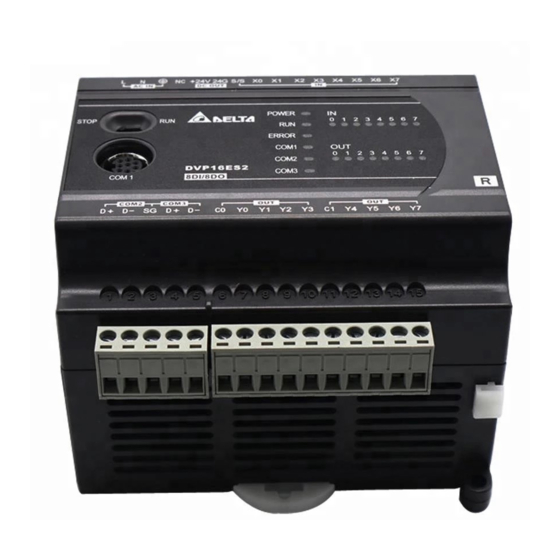
- Page 10 DVP-ES2 DVP-ES2 16 ~ 60 8 ~ 32 DVP-ES2 (OPEN TYPE) Run/Stop C OM 1 DVP40ES2 RS-232C 24 DI / 1 6D O D IN (35mm ) C OM 2/COM 3 (RS-485 ) [Figure 2] 16ES200R/T 24ES200R/T 32ES200R/T 40ES200R/T 60ES200R/T 20EX200R/T 16ES200 24ES200 32ES200...
- Page 11 16ES200 24ES200 32ES200 40ES200 60ES200 20EX200 DC24V 1,500VAC (Primary-secondary) 1,500VAC (Primary-PE) 500VAC (Secondary-PE) 500VDC ESD: 8KV Air Discharge EFT: Power Line: 2KV Digital I/O: 1KV, Analog & Communication I/O: 1KV RS: 26MHz ~ 1GHz 10V/m L, N 0°C ~ 55°C 50 ~ 95% -25°C ~ 70°C 5 ~ 95%...
- Page 12 (A/D) (D/A) 12-bit 12-bit 12-bit 12-bit 40mA 20mA 4000 4000 4000 4000 0.5 or lower > 5K < 500 20mA +10V 2ms ( D1118 ±15V ±32mA 12 bits D1062 D1062 35mm 12-24 AWG 3.80 kg-cm (3.30 Ib-in) 60/75°C • DVP-ES2 (100 ~ 240VAC AC110V AC220V...
- Page 13 1.6mm 10ms 5. +24V 0.5A 5 ~ 7mA 100mA +24V 400mA [Figure 4] 100 ~ 240VAC, 50/60Hz DVP PLC 24VDC 500mA 24VDC SINK SOURCE DC Signal IN – SINK [Figure 5] DC Signal IN – SOURCE [Figure 6] [Figure 7] 5 ~ 10A 1.
- Page 14 [Figure 10] [Figure 11] (Open Collector) Y0/Y1 0.1A [Figure 12] +Zener On/Off [Figure 13] -10V~+10V -10V~+10V VI0- 0mA~20mA -20mA~+20mA VI3- - 13 -...
- Page 15 DVP-ES2 DVP-ES2 16 ~ 60 8 ~ 32 DVP-ES2 (OPEN TYPE) C O M R un/S to p DVP40ES2 C OM 1 24 DI / 1 6D O RS-232C D IN (35m m ) C OM 2/C O M3 (RS -485) D IN [Figure 2] 16ES200R/T 24ES200R/T 32ES200R/T 40ES200R/T 60ES200R/T 20EX200R/T...
- Page 16 16ES200 24ES200 32ES200 40ES200 60ES200 20EX200 DC24V 1,500VAC (Primary-secondary) 1,500VAC (Primary-PE) 500VAC (Secondary-PE) 500VDC ESD: 8KV Air Discharge EFT: Power Line: 2KV, Digital I/O: 1KV, Analog & Communication I/O: 1KV RS: 26MHz ~ 1GHz, 10V/m L, N 0°C ~ 55°C 50 ~ 95% -25°C ~ 70°C 5 ~ 95%...
- Page 17 (A/D) (D/A) -2,000 ~ +2,000 -2,000 ~ +2,000 -2,000 ~ +2,000 0 ~ +4,000 12-bit 12-bit 12-bit 12-bit 40mA 20mA 4000 4000 4000 4000 0.5 or lower > 5K < 500 20mA +10V 2ms ( D1118 ±15 V ±32mA 12 bits D1062 D1062 35mm...
- Page 18 AC220V +24V 1.6mm 10ms 5. +24V 0.5A 5 ~ 7mA 100mA +24V 400mA [Figure 4] 100 ~ 240VAC, 50/60Hz DVP PLC 24VDC 500mA 24VDC DC Signal IN – [Figure 5] DC Signal IN – [Figure 6] [Figure 7] 5 ~ 10A [Figure 8] +Zener On/Off...
- Page 19 [Figure 10] [Figure 11] (Open Collector) Y0/Y1 0.1A [Figure 12] +Zener On/Off [Figure 13] -10V~+10V -10V~+10V VI0- 0mA~20mA -20mA~+20mA VI3- - 18 -...