Sign In
Upload
Manuals
Brands
Delta Electronics Manuals
Controller
AH500
Delta Electronics AH500 Manuals
Manuals and User Guides for Delta Electronics AH500. We have
2
Delta Electronics AH500 manuals available for free PDF download: Operation Manual, Manual
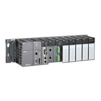
Delta Electronics AH500 Operation Manual (566 pages)
Brand:
Delta Electronics
| Category:
Controller
| Size: 19.41 MB
Table of Contents
Ah500 Operation Manual
4
Table of Contents
4
Chapter 1 Introduction
15
Description of Models
15
Related Manuals
15
Overview
21
Characteristics
23
Chapter 2 Specifications and System Configuration
32
General Specifications
34
Specifications for CPU Modules
34
Performance Specifications
35
Profiles
37
Basic System Configuration
39
Introduction
39
Configuring a Main Backplane
40
Configuring an Extension Backplane
41
Maximum Extension
41
Specifications for Digital Input/Output Modules
42
General Specifications
42
Profiles
45
Dimensions
53
Arrangement of Input/Output Terminals
58
Specifications for Analog Input/Output Modules
66
General Specifications
66
Profiles
70
Dimensions
72
Arrangement of Input/Output Terminals
73
Setting Parameters
74
Specifications for Temperature Measurement Modules
77
General Specifications
77
Profiles
79
Dimensions
81
Arrangement of Input/Output Terminals
82
Setting Parameters
83
Specifications for Network Modules
84
General Specifications
84
Profiles
87
Dimensions
96
Arrangement of Input/Output Terminals
99
Setting Parameters
100
Specifications for Motion Control Modules
103
General Specifications
103
Profiles
114
Dimensions
120
Arrangement of Input/Output Terminals
123
Setting Parameters
128
Specifications for Remote Input/Output Modules
130
General Specifications
130
Profiles
131
Dimensions
135
Specifications for Power Supply Modules
137
General Specifications
137
Profiles
138
Dimensions
139
Arrangement of Terminals
140
Space Module, Backplanes, and Extension Cables
141
General Specifications
141
Profiles
142
Dimensions
145
Chapter 3 Installing Software
150
Installing and Uninstalling Ispsoft
151
Installing Ispsoft
151
Uninstalling Ispsoft
155
Installing and Uninstalling COMMGR
156
Installing COMMGR
156
Uninstalling COMMGR
158
Chapter 4 Installing Hardware
160
Installation
161
Mounting a Backplane
161
Installing a Module
163
Wiring
164
Wiring a Power Supply Module
164
Wiring I/O Modules
166
Chapter 5 Devices
167
Introduction of Devices
168
Devise Table
168
Basic Structure of I/O Storages
170
Relation between the PLC Action and the Device Type
170
Latched Areas in the Device Range
171
Functions of Devices
171
Values and Constants
172
Floating-Point Numbers
172
Strings
172
Input Relays
172
Output Relays
173
Auxiliary Relays
173
Special Auxiliary Relays
173
Stepping Relays
173
Timers
174
Counters
174
32-Bit Counters
175
Data Registers
176
Special Data Registers
176
Link Registers
176
Index Registers
176
Chapter 6 Writing a Program
177
Quick Start
178
Example
178
Hardware
178
Program
178
Creating a Project
179
Procedure for Creating a Project in Ispsoft
179
Hardware Configuration
180
Configuring a Module
181
Setting the Parameters in a CPU Module and a Module
182
Creating a Program
184
Adding a Ladder Diagram
184
Basic Editing─Creating a Contact and a Coil
186
Basic Editing─Inserting a Network and Typing an Instruction
189
Basic Editing─Selection of a Network and Operation
191
Basic Editing─Connecting a Contact in Parallel
192
Basic Editing─Editing a Comment
193
Basic Editing─Inserting an Applied Instruction
194
Writing a Program
197
Checking and Compiling a Program
198
Testing and Debugging a Program
199
Creating a Connection
199
Downloading a Program and Parameters
201
Connection Test
203
Setting a Real-Time Clock
209
Chapter 7 Memory Card
211
Overview of Memory Cards
212
Appearances of Memory Cards
212
Specifications for SD Cards
212
Using a Memory Card
213
Formatting a Memory Card
213
Write Protect Function of a Memory Card
214
Installing and Removing a Memory Card
215
SD Slot in a CPU Module
215
Installing a Memory Card
215
Removing a Memory Card
215
Contents of a Memory Card
216
Initializing a Memory Card
216
Folder Structure in a Memory Card
216
Reading/Writing a Memory Card
217
Backing up the System
217
Restoring the System
217
Introduction of CARD Utility
218
Backup
220
Restoration
223
Chapter 8 Hardware Configuration
227
Hardware Configuration Tool for AH500 Series Modules─Hwconfig
229
Introduction of the Environment of HWCONFIG
229
Configuring a Module
231
Adding a Module
231
Assigning Devices to a Module
234
Editing a Comment
238
Deleting a Module
239
Replacing a Module
239
Searching For/Replacing a Module
240
Copying/Pasting a Module
244
Cutting/Pasting a Module
246
Dragging a Module
247
Adding an Extension Rack
248
Deleting a Rack
249
Replacing a Rack
250
Cutting/Copying/Pasting an Extension Rack
251
Dragging an Extension Rack
254
Rearranging the Input/Output Devices
254
Setting the Parameters in an AH500 Series CPU Module
255
Opening the PLC Parameter Setting Window
255
Setting the Basic CPU Parameters
256
CPU: Name
256
CPU: System
257
CPU: Latched Device Range
260
COM Port
262
Ethernet─Basic
263
Ethernet─Advance
264
Ethernet─Advance: Filter
264
Ethernet─Advance: NTP
266
Ethernet─Advance: Email
267
Ethernet─Advance: Email Trigger
268
Ethernet─Advance: Email and Trigger Configuration
272
Ethernet─Advance: Socket
273
Ethernet─Advance: Web
275
Saving and Downloading/Uploading the PLC Parameters
276
Setting the Parameters in an AH500 Series Module
277
Managing the Version of a Module
277
Setting the Parameters in a Module
278
Exporting and Importing the Parameters in a Module
282
Setting the Parameters in an Intelligent Module
283
Management of the Parameters in AH500 Series Hardware and Online Diagnosis
284
Saving and Printing a Hardware Configuration
284
Purchase Order
285
Rack Information List
286
Downloading/Uploading the System Parameters
287
I/O Scan
288
Online Diagnosis
289
Online Mode
290
Module Information and Diagnosis
291
Changing the Status of a Module Online
292
Monitoring Table
294
Setting Interrupts
295
Program Architectures
295
Tasks Supported by AH500 Series CPU Modules
295
I/O Interrupts
296
Communication Interrupts
298
External Interrupts
298
Timer Interrupts
299
Chapter 9 Network Configuration (Applicable for Ahcpu5X0 Models)
301
Network Configuration Tool─Nwconfig
302
Introduction of NWCONFIG
302
Basic Knowledge
303
Communication Setting in NWCONFIG
304
Connection Mechanism in NWCONFIG
305
Setting Communication Parameters
306
Workflow
307
Creating a Network Architecture
312
Deploying Nodes
312
Connecting to a Network
315
Adjusting or Deleting Devices or Networks
320
Setting the Attributes of a Node/Network
323
Hiding/Displaying Devices or Networks
327
Correct Network Architecture
330
Downloading Routing Tables
333
Testing Routing
334
Managing and Applying NWCONFIG
336
Saving Parameters and Printing a Network Framework
336
Downloading Parameters
337
Introduction of Parameters
337
Description of Downloading Parameters
338
Using Routing in Ispsoft
339
Chapter 11 Convenient Functions
345
PLC Link (for AHCPU5X0 Models)
346
Introduction of a PLC Link
346
Constructing a PLC Link in NWCONFIG in Ispsoft
346
Opening the PLC Link Table Editor Window
347
Designating a Port as a Master Station (Step 1)
348
Setting Communication Parameters (Step 2)
350
Creating a Data Exchange Table (Step 3)
351
Monitoring a PLC Link
358
Important Points about Constructing a PLC Link
362
Executing a PLC Link through the Program in Ispsoft
364
Parameters Related to a PLC Link
364
Setting a PLC Link
369
Related Special Auxiliary Relays and Special Data Registers
375
Ether Link (for AHCPU5X0 Models)
377
Introduction of an Ether Link
377
General Specifications and Functions
378
Steps of Constructing an Ether Link
379
Constructing an Ether Link in NWCONFIG in Ispsoft
380
Constructing an Ether Link
380
Opening the Ether Link Configuration Window
380
Creating and Managing a Data Exchange Table
382
Node List and Display Area
385
Start Mode of an Ether Link
387
Downloading the Parameters Related to an Ether Link
389
Uploading the Parameters Related to an Ether Link
391
Deleting Asynchronous Device
392
Enabling/Disabling the Online Monitoring Function
393
Starting/Stopping the Execution of an Ether Link Online
397
Monitoring Table and Error Log
400
Related Special Auxiliary Relays and Special Data Registers
401
Data Exchange Function
404
MODBUS Data Exchange
404
MODBUS Data Exchange - PLC Parameter Setting
404
MODBUS Data Exchange - Downloading/Uploading Parameters
407
MODBUS TCP Data Exchange
425
MODBUS TCP Data Exchange - PLC Parameter Setting
426
MODBUS TCP Data Exchange - Downloading/Uploading Parameters
430
MODBUS TCP Data Exchange - Special Auxiliary Relays
432
Web
460
Introduction
460
Usage
460
Troubleshooting
462
Ethernet/Ip
465
Chapter 12 Troubleshooting
467
Troubleshooting
468
Basic Inspection
468
Eliminating Errors
468
Troubleshooting Procedure
469
Viewing Error Logs
470
Troubleshooting for CPU Modules
471
ERROR LED Indicator's Being on
471
ERROR LED Indicator's Blinking
473
BUS FAULT LED Indicator's Being on
478
BUS FAULT LED Indicator's Blinking
479
Troubleshooting for AH500 Redundancy System
480
Troubleshooting for Ethernet/Ip
490
Others
491
Troubleshooting for I/O Modules
507
Troubleshooting for Analog I/O Modules and Temperature Measurement Modules
507
Troubleshooting for AH02HC-5A/AH04HC-5A
510
Troubleshooting for AH05PM-5A/AH10PM-5A/AH15PM-5A
511
Troubleshooting for AH20MC-5A
513
Troubleshooting for AH10EN-5A/AH15EN-5A
514
Troubleshooting for AH10SCM-5A/AH15SCM-5A
514
Troubleshooting for AH10DNET-5A
515
Troubleshooting for AH10PFBM-5A
516
Troubleshooting for AH10PFBS-5A
516
Troubleshooting for AH10COPM-5A
517
Error Codes and LED Indicators
518
CPU Modules
519
Analog I/O Modules and Temperature Measurement Modules
541
Ah02Hc-5A/Ah04Hc-5A
542
Ah05Pm-5A/Ah10Pm-5A/Ah15Pm-5A
543
Ah20Mc-5A
544
Ah10Dnet-5A
545
Ah10En-5A/Ah15En-5A
545
Ah10Scm-5A/Ah15Scm-5A
545
Ah10Pfbm-5A
546
Ah10Copm-5A
547
Ah10Pfbs-5A
547
Appendix A Installing a USB Driver
550
Installing the USB Driver for an AH500 Series CPU Module in Windows XP with SP3
550
Installing the USB Driver for an AH500 Series CPU Module in Windows 7
554
Installing the USB Driver for an AH500 Series CPU Module in Windows 8
558
Installing the USB Driver for an AH500 Series CPU Module in Windows 10
561
Advertisement
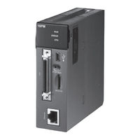
Delta Electronics AH500 Manual (547 pages)
Motion Control Module
Brand:
Delta Electronics
| Category:
Controller
| Size: 9.44 MB
Table of Contents
Table of Contents
2
Chapter 1 Framework of an AH500 Series Motion Control Module
10
Framework of a AH500 Series Motion Control Module
11
Structure of O100
13
Manual Function of O100
14
Structure of Ox Motion Subroutines
14
Structure of P Subroutines
16
Using O100, Ox Motion Subroutines, and P Subroutines
19
Structure of a Program
19
Chapter 2 Hardware Specifications and Wiring
22
Hardware Specifications
23
General Specifications
23
Electrical Specifications for the Input Terminals
23
Electrical Specifications for the Output Terminals
30
Dimensions
35
Profiles
37
Wiring
40
I/O Extension Cables, and External Terminal Modules
41
Wiring Input Terminals
46
Wiring Output Terminals
48
Wiring AH10PM-5A and an Inferior Servo Drive
51
Communication Ports
56
Chapter 3 Devices
58
Device List
59
Values, Constants, and Floating-Point Numbers
59
External Input Devices and External Output Devices
61
Auxiliary Relays
63
Special Auxiliary Relays
63
Stepping Relays
63
Timers
63
Counters
64
Data Registers and Index Registers
69
Data Registers
69
Index Registers
69
Special Data Registers
70
Pointers
70
Special Auxiliary Relays
70
Special Data Registers
74
Functions of Special Auxiliary Relays and Special Data Registers
85
Special Data Registers for Motion Axes
97
Chapter 4 Basic Instructions
100
Table of Basic Instructions
101
Descriptions of the Basic Instructions
103
Chapter 5 Applied Instructions
116
Table of Applied Instructions
118
Structure of an Applied Instruction
124
Processing Values
126
Using Index Registers to Modify Operands
129
Instruction Index
129
Descriptions of the Applied Instructions
133
Motion Control Function Block Table
241
Introduction of the Pins in a Motion Control Function Block
243
Definitions of Input Pins/Output Pins
243
Timing Diagram for Input/Output Pins
245
Introducing the Use of Pmsoft
246
Delta-Defined Parameter Table
248
Uniaxial Motion Control Function Blocks
251
Absolute Single-Speed Motion
251
Relative Single-Speed Motion
254
Absolute Two-Speed Motion
259
Relative Two-Speed Motion
263
Inserting Single-Speed Motion
267
Inserting Two-Speed Motion
271
JOG Motion
275
Manual Pulse Generator Mode
278
Returning Home
281
Stopping Uniaxial Motion
284
Chapter 7 Uniaxial Motion
384
Functions of Uniaxial Motion
385
Introduction of Uniaxial Motion
397
Introduction of JOG Motion
398
Related Special Data Registers
398
Operation
399
Introduction of Variable Motion
400
Related Special Data Registers
400
Operation
400
Introduction of a Manual Pulse Generator Mode
401
Related Special Data Registers
401
Operation
403
Introduction of a Mode of Triggering the Return to Home
403
Related Special Data Registers
403
Introduction of Single-Speed Motion
409
Related Special Data Registers
409
Operation
410
Introduction of Inserting Single-Speed Motion
411
Related Special Data Registers
411
Operation
412
Introduction of Two-Speed Motion
413
Related Special Data Registers
413
Operation
414
Introduction of Inserting Two-Speed Motion
415
Related Special Data Registers
415
Operation
416
Status Flags and Status Registers
417
Chapter 8 Electronic Cam
420
Introduction of Electronic Cams
421
Operation of an Electronic Cam
422
Initial Setting
422
Creating Electronic Cam Data
422
Setting an Input/A Output Pulse Type
422
Setting a Master/Slave Axis and Operating an Electronic Cam
424
Setting a Master Axis
424
Setting the Starting Angle of a Master Axis
425
Setting a Slave Axis
426
Starting/Stopping an Electronic Cam Operating Cyclically
426
Staring an Electronic Cam Operating Cyclically
426
Stopping an Electronic Cam Operating Cyclically
427
Creating Electronic Cam Data
429
Creating a CAM Chart in Pmsoft
429
Function Relates the Positions of a Master Axis to the Positions of a Slave Axis
429
Measuring the Relation between the Positions of a Master Axis and the Positions of a Slave Axis at Work
433
Creating/Modifying Electronic Cam Data
435
Application of an Electronic Cam-Using a Rotary Cutter
437
Creating Rotary Cut Data
439
Function Block-T_Camcurve
440
Function Block-T_Camcurveupdate
445
Example
446
Chapter 9 Multiaxial Interpolation
450
Composition of a G-Code
451
Introduction of Multiaxial Interpolation
451
Table of O Pointers/M-Codes and Table of G-Codes
451
Descriptions of G-Code Instructions
454
O Pointers/M-Codes
471
Description of to
473
Chapter 13 Expansion Storage Device
507
Functions
507
Parameters
507
Reading and Executing G-Codes
509
Device Backup and Restoration
509
Backup
510
Restoration
511
Program Backup and Restoration
512
Backup
512
Restoration
513
Updating Firmware
513
Chapter 14 DMCNET
517
Functions
517
Specifications
517
Parameters
518
DMCNET Connection
522
Reading Data from a Servo Drive/Writing Data into a Servo Drive
524
DMCNET Motion Control
526
Examples
531
Connecting an Incremental Servo Drive
531
Connecting an Absolute Servo Drive
532
Troubleshooting
533
Advertisement
Related Products
Delta Electronics AC Motor Drive VFD-EL
Delta Electronics ASD-A2-0121 Series
Delta Electronics ASD-A2-0221 Series
Delta Electronics ASD-A2-0721 Series
Delta Electronics ASD-A2-2023 Series
Delta Electronics ASD-A2-3023 Series
Delta Electronics ASD-A2-0743 Series
Delta Electronics ASD-A2-1543 Series
Delta Electronics ASD-A2-3043 Series
Delta Electronics ASD-A2-2043 Series
Delta Electronics Categories
Power Inductor
Power Supply
Computer Hardware
Fan
Transceiver
More Delta Electronics Manuals
Login
Sign In
OR
Sign in with Facebook
Sign in with Google
Upload manual
Upload from disk
Upload from URL