Table of Contents
Advertisement
MIDI SOUND GENERATOR
POWER
VOLUME
PART
INSTRUMENT
ALL
- SOUND Canvas -
LEVEL
PAN
127
0
REVERB
CHORUS
PREVIEW (PUSH)
64
64
K SHIFT
MIDI CH
± 0
A--
1 2 3 4 5 6 7 8 9 10 11 12 13 14 15 16
DELAY
MIDI IN B
PHONES
OWNER'S MANUAL
PART
ALL
LEVEL
MUTE
REVERB
SC - 55
MAP
KEY SHIFT
SC - 88
MAP
PART
DELAY
VIB RATE
VIB DEPTH
CUTOFF
USER
INST
SELECT
ATTACK
DECAY
EFX
EFX
ON/OFF
ON/OFF
EFX TYPE
EFX
TYPE
EFX P
EFX PARAM
ARAM
INSTRUMENT
PAN
CHORUS
MIDI CH
VIB DELAY
RESONANCE
RELEASE
EFX VALUE
EFX V
ALUE
Advertisement
Table of Contents

Related Manuals for Roland SoundCanvas SC-88 Pro


Summary of Contents for Roland SoundCanvas SC-88 Pro
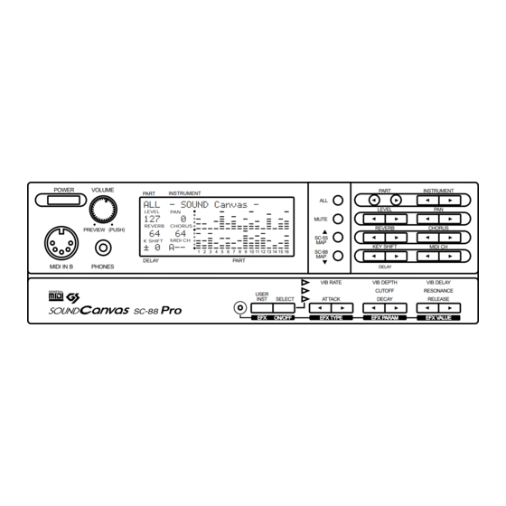
- Page 1 MIDI SOUND GENERATOR POWER VOLUME PART INSTRUMENT - SOUND Canvas - LEVEL REVERB CHORUS PREVIEW (PUSH) K SHIFT MIDI CH ± 0 1 2 3 4 5 6 7 8 9 10 11 12 13 14 15 16 DELAY PART MIDI IN B PHONES USER...
-
Page 2: Important Safety Instructions
CAUTION RISK OF ELECTRIC SHOCK DO NOT OPEN ATTENTION : RISQUE DE CHOC ELECTRIQUE NE PAS QUVRIR CAUTION: TO REDUCE THE RISK OF ELECTRIC SHOCK, DO NOT REMOVE COVER (OR BACK). NO USER-SERVICEABLE PARTS INSIDE. REFER SERVICING TO QUALIFIED SERVICE PERSONNEL. INSTRUCTIONS PERTAINING TO A RISK OF FIRE, ELECTRIC SHOCK, OR INJURY TO PERSONS. -
Page 3: Using The Unit Safely
Copyright 1996 ROLAND CORPORATION All rights reserved. No part of this publication may be reproduced in any form without the written permission of ROLAND COR- PORATION. or warnings.The specific meaning of the symbol is determined by the design contained within the... -
Page 4: Introduction
This unit is a sound module compatible with the General MIDI system. It can be used to play- back any song data (General MIDI scores) bearing the General MIDI logo. This unit is also compatible with the Roland GS format. It can be used to playback any song data bearing the GS logo. -
Page 5: Important Notes
However, in certain cases (such as when circuitry related to memory itself is out of order), we regret that it may not be possible to restore the data, and Roland assumes no liability concerning such loss of data. Memory Backup This unit contains a battery which powers the unit's memory circuits while the main power is off. -
Page 6: Table Of Contents
CONTENTS USING THE UNIT SAFELY ...1 Introduction ...2 IMPORTANT NOTES ...3 CONTENTS ...4 Front and rear panel ...6 Chapter 1. Try out the unit (Quick start) Connect a MIDI keyboard and play the sounds...8 Making connections...8 Turning the power on or off ...9 Is there sound?...9 Try out the various sounds ...10 Try out the buttons of the unit...11... - Page 7 Chapter 5. Convenient functions Create and save a sound (User Instrument) ..96 Creating and saving an Instrument effect (User Effect) ...99 Creating and saving a Patch(User Patch) ...100 Saving a Drum Set you created (User Drum) Copying or Exchanging settings between Parts / Initializing Part settings ...106 Recording all settings on a sequencer ...107 Bulk Dump procedure...107...
-
Page 8: Front And Rear Panel
Front and rear panel Front panel MIDI IN B connector (front) (p.135) When IN B Select is set to Rear (the factory setting), the front MIDI IN B connector cannot be used. Power switch (p.9) Volume knob (p.9) Preview switch (p.11) Headphone jack (p.15) POWER VOLUME... -
Page 9: Chapter 1. Try Out The Unit (Quick Start)
Chapter 1 Try out the unit (Quick start) -
Page 10: Connect A Midi Keyboard And Play The Sounds
Connect a MIDI keyboard and play the sounds Making connections * This section explains how to connect this unit to a MIDI keyboard and play the sounds. If you wish to connect a sequencer or personal computer to this unit, refer to p.120. * To prevent malfunction and/or damage to speakers or other devices, always turn down the vol- ume, and turn off the power on all devices before making any connections. -
Page 11: Turning The Power On Or Off
Turning the power on or off Once the connections have been completed , turn on power to your various devices in the order specified. By turning on devices in the wrong order, you risk causing mal- function and/or damage to speakers and other devices. Turning the power on Before you turn the power on, check the following points. -
Page 12: Try Out The Various Sounds
Try out the various sounds This unit contains a wide variety of sounds, including not only musical instruments such as piano, organ and guitar, but also sound effects such as birds and telephone rings. In this unit, each of these sounds is called an “Instrument”. A group of Instruments is called a “Map.”... -
Page 13: Try Out The Buttons Of The Unit
Try out the buttons of the unit Preview the sound (Preview) When you press the Volume knob, the currently selected instrument will sound. You can specify the pitch and volume at which this preview note will be sounded (p.37). This preview function is convenient when you wish to check sounds or adjust the tuning when a keyboard is not connected. - Page 14 Transpose the pitch You can transpose the pitch of the sound in semitone steps. Pressing KEY SHIFT [l] will lower the key (pitch), and pressing KEY SHIFT [r] will raise the key (pitch). * The area of the screen where the Key Shift setting is displayed is shared with the Delay display. When while holding down the [SC-88 MAP] button, press [DELAY] buttons, the delay setting will be displayed, and when you press the [KEY SHIFT] buttons the key shift setting will be dis- played.
-
Page 15: Apply Effects To The Sound
Apply effects to the sound Effects are used to electrically process the sound in various ways to add a different character to the sound. The effects of this unit can be classified either as System effects (p.48) or as Insertion effects (p.56). System effects include 8 types each of reverb and chorus, 10 types of delay, and 2-band equalizer. -
Page 16: Tuning To Other Instruments (Tuning)
Tuning to other instruments (Tuning) M. Tune (Master Tune) 415.3 — 466.2 Hz When you are playing in an ensemble with other instruments or need to set this unit to match the pitch of another instrument, adjust the Master Tune setting. The displayed value (e.g., 440.0 Hz) indicates the frequency of the A4 note's pitch (note number 69). -
Page 17: Headphones
Headphones Use headphones of 8 — 150 ohms impedance. Sound will be output from the audio output jacks even when headphones are connected. Stereo Headphones * The headphone jack will output the sound of OUTPUT1.This means that the sound of Parts assigned to OUTPUT2 will not be heard from the headphone jack. - Page 18 Chapter 1. Try out the unit...
-
Page 19: Chapter 2. Parts And Parameters
Chapter 2 Parts and parameters... -
Page 20: Parts And Sounds
Parts and sounds This unit is able to produce 32 different types of sound at once. An instrument such as this unit, which can simultaneously produce many sounds from a single unit's is called a multi-timbral sound generator. A Timbre is an instrumental sound. Being able to simultaneously play 32 sounds means that you can use 32 different instruments at once. - Page 21 To select the same sounds as the SC-55/SC-55mk II 4-1. Press [SC-55 MAP], and the sound for that Part will be almost the same as the SC-55/55mk II. At this time “ ” will be displayed in front of that Instrument name. PART LEVEL * It is also possible to select the CM-64 Instrument layout.
-
Page 22: Selecting Variation Sounds
Selecting Variation sounds Each of the three sound maps of this unit contains Capital sounds (basic sounds) and Variation sounds (sounds with different nuances). The procedure explained on the pre- vious page selects Capital sounds (128 sounds; Instrument list, p.154). Here's how to select Variation sounds. -
Page 23: Reading The Instrument Numbers And Variation Numbers
A symbol will be displayed in front of the sound name to indicate the type of sounds you are selecting. blank Capital sounds (Variation number 000) “ ” Variation sounds (Variation number 001 — 125) “ ” SC-88 sounds (SC-88 map) “... -
Page 24: Part Channels
Part Channels To each of this unit's 32 Parts, there is assigned an instrument and also a Channel. Channels are a concept used in MIDI to distinguish notes that should be played by dif- ferent instruments in an ensemble. Normally, there is no need to change the channel of a Part when using this unit. -
Page 25: Which Midi In Will Be Used By Each Part
Which MIDI IN will be used by each Part? MIDI IN A Part group A Part A01 Part A02 Part A15 This unit has two MIDI IN jacks. This is because since there are only 16 MIDI chan- nels, it is necessary to have two MIDI jacks in order to play 32 Parts. Parts are classified into Group A (A01 —... -
Page 26: How Simultaneous Note Numbers And Voices Are Related
How simultaneous note numbers and Voices are related The sounds of this unit consist of units called “Voices”. There is a limit to how many of these “Voices” can sound at once, and in the case of this unit, up to 64 simultaneous voices can be used. -
Page 27: Part Parameters For Performance
Part parameters for performance These parameters determine how each Part behaves when it receives MIDI mes- sages. The way in which the sound changes in response to messages such as velocity, pitch bend, modulation and aftertouch will be determined by the settings of these para- meters. -
Page 28: Parameters That Must Be Selected From The Menu
[2] Parameters that must be selected from the menu The following parameters can be selected. Part EQ (Part Equalizer) Part Mode (Part Mode) M/P Mode (Mono/Poly Mode) Fine Tune (Fine Tune) Rx Bank Sel (Bank Select Receive Switch) Rx NRPN (NRPN Receive switch) Velo Depth (Velocity Sens Depth) -
Page 29: What Each Parameter Does
What each parameter does LEVEL (Volume level): 0 — 127 This parameter adjusts the volume of each Part. Higher values result in a louder sound. PAN (Panning): Rnd, L63 — 0 — R63 Pan refers to the position in the stereo field. For exam- ple, you might place the drum set and bass in the cen- ter, the guitar at the right, and the keyboard at the left. - Page 30 The Drum1 and Drum2 Parts allow you to simultane- ously use two drum sets. For example if Drum Parts are set as shown below, when you change the STAN- DARD1 drum set of Part A10 to the TR-808, the selec- tion for Part A12 will also change to TR-808.
- Page 31 For example, if you assign two Parts to the same MIDI channel and set the Keyboard Range of one to C-1 — B3 and the other to C4 — G9. Then you could assign different sounds to each Part, and play two different sounds on either side of C4.
- Page 32 Bnd ~ (Bend ~ ) When you move the pitch bend lever or pitch wheel of a MIDI keyboard, pitch bend messages are transmit- ted, modifying the sound. The Bnd ~ parameters spec- ify the way in which the sound will change when these messages are received.
-
Page 33: Part Parameters For Sound Editing
Part parameters for sound editing On this unit, you can modify the values of a variety of parameters in order to create the sound most suitable for your playing. A “parameter” is something that affects the sound. The process of modifying parameter values is called “editing.” Sound parameters affect the volume, timbre and pitch of the sound. -
Page 34: Part Instrument
(Example) Vibrato editing display select a parameter What each parameter does On this unit, parameter settings are made for each Part. In other words, parameter values belong to Parts, and not to sounds (Instruments). For example if you set Vibrato Rate to +20 and then select a different sound for that Part, the Vibrato Rate of +20 will apply to the newly selected sound (not the initial value of 0). - Page 35 This shape is called the “envelope.” The envelopes of musical instrument sounds can change depending on how the instrument is played. For example if a trumpet is played sharply and strongly, the attack will be quick and the sound will be sharp.
-
Page 36: Setting Parameters Common To All Parts
Setting parameters common to all Parts Here's how to make settings for parameters that are common to all Parts. This procedure allows you to set the following parameters. LEVEL [l] [r] PAN [l] [r] KEY SHIFT [l] [r] : transpose all Parts [MUTE] [SC-55 MAP] [SC-88 MAP]... -
Page 37: How Each Parameter Works
How each parameter works * The settings made here apply to all Parts (when the [ALL] indicator is lit). If you wish to make settings independently for each Part, use the procedure of p.25. LEVEL (Master level): 0 — 127 This parameter adjusts the volume of all the Parts. -
Page 38: System Parameter Settings
System parameter settings This section explains how to make settings for parameters that affect this entire unit. These parameters are called System parameters. System parameters are as follows. Prevw Note Prevw Velo Display Peak Hold LCD Contrast Backup IN B Sel. OUT/THRU In Mode Rx Sys. -
Page 39: How Each System Parameter Works
How each System parameter works Prevw Note (Preview Note Name): C-1 — G9 When you press the PREVIEW knob, the instrument shown in the display will sound. The Prevw Note para- meter determines the note that will be sounded at this time. - Page 40 LCD Contrast: 1 — 16 Depending on the angle at which this unit is placed, the display can sometimes be difficult to read. If so, adjust the contrast of the display. Higher values will make the characters darker. PART INSTRUMENT LEVEL Backup (Backup Switch): On/Off When the power is turned off, this unit preserves...
-
Page 41: Using Patches
Using Patches On this unit, the instrument and effect parameters are collectively referred to as a Patch. This unit provides 128 Preset Patches in which these parameters are already set to ideal settings. (p.186) Patch numbers 001 — 128: The Preset Patches contain high-quality sounds together with optimal settings for other parameters such as effects, making this unit immediately useful as an expansion sound module for your keyboard, etc. -
Page 42: Loading A Patch
Loading a Patch Press the [ALL] button to make the button indicator light. Use INSTRUMENT [l l l l ] [r r r r ] to select the Patch that you wish to load. The Patch name will appear, and the [ALL] button and [MUTE] button will blink. PART LEVEL Press the [ALL] button to load the Patch. -
Page 43: Using Midi Messages To Select Patches
Using MIDI messages to select Patches Normally when a MIDI program change message is received, the Instrument of a Part will change. However if you set the MIDI channel for the Patch, the Patch will change when a program change message is received (p.131). With the Patch MIDI CH settings of “... -
Page 44: Creating A Drum Set (Drum Edit)
Creating a Drum Set (Drum Edit) A Drum Part has assigned to it a group of various percussion instrument sounds which are called a Drum Set. Unlike a Normal Part, a Drum Part sounds a different instrument for each note number. Since a Drum Part needs to simultaneously produce a wide variety of sounds such as bass drum, snare, tom and cymbal, this is very conve- nient. - Page 45 Part Group Part Mode Drum set number PART INSTRUMENT LEVEL Note Name Note name MIDI note number * The Note name is the name of each note (key) on the keyboard, and corresponds to the MIDI Note Number. The Drum instrument is assigned to note number. Use the INSTRUMENT [l l l l ] [r r r r ] buttons select the Drum Instrument you wish to edit.
-
Page 46: Using Chorus And Delay
Using Chorus and Delay In the case of a Drum Instrument, it is not possible to simultaneously use both chorus and delay. Chorus will not be applied to a Drum Instrument for which “ ” and “ ” is dis- played in the CHORUS column (Fig.2). -
Page 47: Chapter 3. System Effects
Chapter 3 System Effects... -
Page 48: How The Effect Section Of The Unit Is Organized
How the effect section of the unit is organized The effects of this unit can be categorized into System effects (p.48) and Insertion effects (p.56). System effects include 8 types of reverb and chorus, 10 types of delay, and 2-band equalizer. - Page 49 Single Module Mode Reverb Send Level Chorus Send Level Delay Send Level Insertion effect Part group A (EFX) Equalizer On/Off Part A1 - A16 ON/OFF Level Part group B Part B1 - B16 Double Module Mode Reverb Send Level Chorus Send Level Insertion effect (EFX) Level...
-
Page 50: System Effect Settings
System Effect settings The System effects of this unit include 8 types of reverb and chorus, and 10 types of delay. In addition, for each of these effects you can specify parameter values such as character, depth, rate and time. Reverb is an effect that adds reverberation to a sound, as you would hear in a concert hall. -
Page 51: Equalizer Parameter Functions
Use the EFX PARAM [l l l l ] [r r r r ] buttons to adjust the EQ Gain(Low) or the Low Frequency. Use the EFX VALUE [l l l l ] [r r r r ] buttons to adjust the EQ Gain(High) or the High Frequency. -
Page 52: When You Want To Adjust The System Effect For All Parts
When you want to adjust the system effect for all Parts Press [ALL] to make the button indicator light. Press the button of the effect you wish to adjust. REVERB [l] [r] : reverb level of all Parts CHORUS [l] [r] : chorus level of all Parts DELAY [l] [r] (while holding down the [SC-88 MAP]) When you perform the following operation, the current parameter value will be displayed graphically. -
Page 53: Setting Reverb/Chorus/Delay Parameters
Setting Reverb/Chorus/Delay parameters Press [ALL] to make the button indicator light. Simultaneously press both the PART [l l l l ] [r r r r ] buttons. Use [u u u u ] [d d d d ] to select the parameter you wish to modify. While holding the [SELECT] button, press[u][d] to skip parameters. -
Page 54: Reverb Parameter Function
Reverb parameter function Reverb (Reverb Type) You can choose from 8 types of reverb. Room1 Room2 Room3 These reverbs simulate the reverberation of a room. They provide a well-defined spacious reverberation. Hall1 Hall2 These reverbs simulate the reverberation of a concert hall. -
Page 55: Chorus Parameter Function
Chorus parameter function Chorus (Chorus Type) You can choose from 8 types of chorus. Chorus1 Chorus2 Chorus3 These are conventional chorus effects that add spa- ciousness and depth to the sound. Feedback Chorus This is a chorus with a flanger-like effect and a soft sound. -
Page 56: Delay Parameter Function
Delay parameter function * Delay cannot be used when Double Module Mode (p.116) is selected. Delay (Delay Type) You can choose from 10 types of delay. Delay1 Delay2 Delay3 These are conventional delays. 1, 2 and 3 have pro- gressively longer delay times. Delay4 This is a delay with a rather short delay time. -
Page 57: Chapter 4. Insertion Effects
Chapter 4 Insertion Effects... -
Page 58: Insertion Effect Settings
Insertion effect settings This unit has two types of effects: System effects and Insertion effects. Insertion effects provide 64 effect types. Since appropriate parameters are provided for each effects, you can make fine adjustments to the sound for professional-level control. * For details on System effects and Insertion effects, and on the effect structure of this unit, refer to p.46. -
Page 59: Different Effect Types
Different effect types Effect types can be broadly grouped into the following categories. Effects that modify the tone color (filter type) (1 - 4) Effects that distort the sound (distortion type) (5 - 6) Effects that modulate the sound (modulation type) (7 - 13) Effects that affect the level (compressor type) (14 - 15) - Page 60 Spectrum Band 1 (Band 1 gain) Adjust the 250 Hz level. Band 2 (Band 2 gain) Adjust the 500 Hz level. Band 3 (Band 3 gain) Adjust the 1000 Hz (1 kHz) level. Band 4 (Band 4 gain) Adjust the 1250 Hz level. Band 5 (Band 5 gain) Adjust the 2000 Hz level.
- Page 61 Amp Sw (Amp switch) Turn the Amp Type on/off. Low Gain Adjust the gain of the low frequency range. Hi Gain (High gain) Adjust the gain of the high frequency range. #Pan (Output pan) Adjust the stereo location of the output sound. L63 is far left, 0 is center, and R63 is far right.
- Page 62 Peak Adjust the amount of the wah effect that will occur in the area of the center frequency. Lower settings will cause the effect to be applied in a broad area around the center frequency. Higher settings will cause the effect to be applied in a more narrow range.
- Page 63 Pre Filter (Pre filter type) Select the type of filter. : a filter will not be used : cut the frequency range above the Cutoff parameter : cut the frequency range below the Cutoff parameter Cutoff (Cutoff frequency) Adjust the basic frequency of the filter. Pre Dly (Pre delay time) Adjust the time delay from when the direct sound begins until the processed sound is heard.
- Page 64 Low Gain Adjust the gain of the low frequency range. Hi Gain (High gain) Adjust the gain of the high frequency range. Level (Output level) Adjust the output level. 13: Auto Pan The Auto Pan effect cyclically modulates the stereo location of the sound.
- Page 65 +Pan (Output pan) Adjust the stereo location of the output sound. L63 is far left, 0 is center, and R63 is far right. #Level (Output level) Adjust the output level. Effects that broaden the sound (chorus type) 16: Hexa Chorus Hexa-chorus uses a six-phase chorus (six layers of chorused sound) to give richness and spatial spread to the sound.
- Page 66 Cutoff (Cutoff frequency) Adjust the center frequency of the filter for the cho- rus sound for the chorus sound. Pre Dly (Pre delay time) Adjust the time delay from when the direct sound begins until the processed sound is heard. +Rate Adjust the rate of modulation.
- Page 67 Fb Mode is Norm: Delay Delay Fb Mode is Cross: Delay Delay Dly Tm L (Delay time left) Adjust the time from the original sound until when the left delay sound is heard. Dly Tm R (Delay time right) Adjust the time from the original sound until when the right delay sound is heard.
- Page 68 HF Damp 315 - 8k/Bypass [8] Adjust the frequency above which sound fed back to the effect will be cut. If you do not wish to cut the high frequencies of the feedback, set this parameter to Bypass. #Balance (Effect balance) D>...
- Page 69 +Feedback (Feedback level) Adjust the proportion (%) of the Dlay 1 sound that is fed back into the effect. Negative (-) settings will invert the phase. HF Damp 315 - 8k/Bypass [10] This adjusts the frequency at which the high range is cut when the Delay 1 sound is returned to the input.
- Page 70 Low Gain Adjust the gain of the low frequency range. Hi Gain (High gain) Adjust the gain of the high frequency range. Level (Output level) Adjust the output level. 27: Gate Reverb Gate Reverb is a special type of reverb in which the reverberant sound is cut off before its natural length.
- Page 71 Effects that modify the pitch (pitch shift type) 29: 2 Pitch Shifter ( 2-voice pitch shifter) A Pitch Shifter shifts the pitch of the original sound. This 2-voice pitch shifter has two pitch shifters, and can add two pitch shifted sounds to the original sound. Pitch 1 Pitch 2 +Coarse 1 (Coarse pitch 1)
- Page 72 Others 31: 3D Auto The 3D Auto effect rotates the location of the sound. 3D Auto Azimuth 180/L168 - 0 - R168 [1] Set the location at which the sound will stop when rotation is stopped. A setting of 0 positions the sound in the center. +Speed Set the speed of rotation.
- Page 73 Cutoff (Cutoff Frequency) Specify the cutoff frequency of the filter that is applied after the sound passes through the Lo-Fi effect. +R.Detune (Radio Detune) This simulates the tuning noise of a radio. As this value is raised, the tuning will drift further. R.Nz Lev (Radio Noise Level) Adjust the volume of the radio noise.
- Page 74 Level (Output level ) Adjust the output level. 36: OD Flanger (Overdrive This effect connects an overdrive and a flanger in series. Overdrive Flanger OD Drive (Overdrive drive ) Adjust the degree of overdrive distortion. The vol- ume will change together with the degree of distor- tion.
- Page 75 Low Gain Adjust the low frequency gain. Hi Gain (High gain ) Adjust the high frequency gain. Level (Output level ) Adjust the output level. 38: DS Chorus (Distortion This effect connects a distortion and a chorus in series. Distortion Chorus DS Drive (Distortion drive ) Adjust the degree of distortion.
- Page 76 #FL Bal (Flanger balance) D> 0E - D 0<E [10] Adjust the volume balance between the sound which passes through the flanger and the sound which does not. With a setting of D>0E, only the distortion sound will be output, and with a setting of D 0<E, the distortion sound which passes through the flanger will be output.
- Page 77 Hi Gain (High gain ) Adjust the high frequency gain. Level (Output level ) Adjust the output level. 42: EH Flanger (Enhancer This effect connects an enhancer and a flanger in series. Enhancer Flanger Enhancer +EH Sens (Enhancer Sensitivity ) Adjust the sensitivity of the enhancer.
- Page 78 Cho Rate (Chorus rate ) Adjust the modulation speed of the chorus effect. Cho Depth (Chorus depth ) Adjust the modulation depth of the chorus effect. +Cho Bal (Chorus balance ) Adjust the volume balance between the direct sound and the chorus sound. With a setting of “D> 0E,”...
- Page 79 Cho Dly (Chorus pre delay ) Adjust the time delay from when the direct sound begins until the chorus sound is heard. Cho Rate (Chorus rate ) Adjust the modulation speed of the chorus effect. Cho Depth (Chorus depth ) Adjust the modulation depth of the chorus effect.
- Page 80 RT H Fast (RTRT High Frequency Fast Rate) Adjust the speed of the high-range rotor for the high-speed (Fast) setting. RT Hi Accl (RT High Frequency Accelaration) Adjust the time over which the rotation speed of the high-range rotor will change from low-speed to high-speed (or high-speed to low-speed) rotation.
- Page 81 49: GTR Multi 2 (Guitar Multi2) Guitar Multi 2 provides Compressor (Cmp), Overdrive or Distortion (OD), Equalizer (EQ), and Chorus or Flanger (CF) effects connected in series. <Cmp (Compressor)> Cmp Atck (Compressor Attack) Adjust the time over which the sound will rise after it is input.
- Page 82 Wah Peak Adjust the way in which the wah effect will be applied to the region of the center frequency. Lower settings will produce a wah effect in a broad area around the center frequency, and higher settings will produce a wah effect in a narrower area around the center frequency.
- Page 83 EQ M Gain (EQ Mid Gain) Adjust the gain of the area specified by the EQ M Fq parameter and the EQ M Q parameter. EQ H Gain (EQ High Gain) Adjust the high-range gain of the equalizer. <CF (Chorus/Flanger)> CF Sel (CF Select) Chorus/Flangr [10] Select either Chorus or Flanger.
- Page 84 CF Depth Adjust the depth of modulation for the chorus or flanger. CF Fb (CF Feedback) Adjust the amount (%) of the flanger sound that will be returned to the input. Negative (-) values will invert the phase. In the case of Chorus, this will have no effect. CF Mix Adjust the volume of the chorus or flanger sound.
- Page 85 #CF Mix Adjust the volume of the chorus or flanger sound. Level (Output level ) Adjust the output level. 54: Rhodes Multi Rhodes Multi provides Enhancer (EH), Phaser (PH), Chorus or Flanger (CF), and Tremolo or Pan (TP) effects connected in series. <EH (Enhancer)>...
- Page 86 <RM (Ring Modulator)> +RM Mod Freq (RM Modulation Frequency) Set the frequency at which modulation will be applied. #RM Bal (RM Balance) Adjust the balance between the direct and the ring modulated sound. “D” or “E” on the display respectively means D(direct sound) or E(effect sound) values of 100.
- Page 87 60 OD/Rotary Part 01 L63 028 Clean Gt. Overdrive/ Distortion Part 02 R63 017 Organ 1 Rotary 56: Cho / Delay (Chorus / Delay) This effect connects a chorus and a delay in parallel. Chorus Balance Delay Cho Dly (Chorus pre delay ) Adjust the time delay from when the direct sound begins until the chorus sound is heard.
- Page 88 #Dly Bal (Delay balance ) D> 0E - D 0<E [10] Adjust the volume balance between the direct and the delay sound. “D” or “E” on the display respectively means D(direct sound) or E(effect sound) values of 100. Dly Pan (Delay Output Pan) Adjust the stereo position of the delay sound.
- Page 89 OD1 Amp Sw (OD1 Amp Switch) Turn OD1 Amp on/off. OD1 Pan (OD1 Output Pan) Set the stereo location of the overdrive or distortion sound for set 1. L63 is far left, 0 is center, and R63 is far right. OD1 Level Adjust the overdrive or distortion volume for set 1.
- Page 90 RT H Slow (RT High Frequency Slow Rate) Adjust the speed of the high-range rotor for the low- speed (Slow) setting. RT H Fast (RT High Frequency Fast Rate) Adjust the speed of the high-range rotor for the high-speed (Fast) setting. RT Hi Accl (RT High Frequency Acceleration) Adjust the time over which the rotation speed of the high-range rotor will change from low-speed to...
- Page 91 <OD (Overdrive/Distortion)> OD Sel (OD Select) Select either Overdrive or Distortion. +OD Drive (OD Drive) Adjust the depth of overdrive or distortion. The vol- ume will change together with the depth of distor- tion. OD Amp (OD Amp Simulator Type) Small/BltIn/2-Stk/3-Stk [3] Select the type of guitar amp for overdrive or distor- tion.
- Page 92 <RT (Rotary)> RT L Slow (RT Low Frequency Slow Rate) Adjust the speed of the low-range rotor for the low- speed (Slow) setting. RT L Fast (RT Low Frequency Fast Rate) Adjust the speed of the low-range rotor for the high- speed (Fast) setting.
- Page 93 Adjust the volume of the auto-wah sound. Level (Output level ) Adjust the output level. 0 - 127 [8] The following four 3D effects utilize RSS (Roland Sound Space) technology to create a spacious- 0 - 127 [9] ness that cannot be produced by delay, reverb, or chorus etc.
-
Page 94: Parameters
Using controllers to modify effect parameters Controllers can be used to modify the values of Insertion effect parameters. Using MIDI messages to modify effect parameters during a song would require a large amount of data if you were to use only Exclusive messages. Thus, this unit allows you to use controllers to set the main effect parameters. -
Page 95: How Each Parameter Works
How each parameter works EFX C.Src1, 2 (Effect Control Source) Off/CC1 - 95/CAf/Bend Specify the controllers that you wish to use. EFX C.Src1 will control the parameter marked with a “+” at the left of the parameter name. EFX C.Src2 will control the parameter marked with a “#”... - Page 96 < Modifying values > Since the Speed parameter has only two values, Slow and Fast, the lower half of the range (00H -- 3FH) will select Slow, and the upper half (40H--7FH) will select Fast. B0 10 00 Speed Slow B0 10 3F Speed Slow...
-
Page 97: Chapter 5. Convenient Functions
Chapter 5 Convenient functions... -
Page 98: Create And Save A Sound (User Instrument)
Create and save a sound (User Instrument) You can modify the parameters of this unit sound to your taste, and save your new settings in Variation numbers 64 or 65 of the Native map / SC-88 map (p.98). A sound saved in this way is called a User Instrument, and this procedure is called User Editing. - Page 99 Procedure for creating and storing a sound Make sure that the [ALL] indicator is dark. If it is lit, press the [ALL] button to turn it off. Use PART [l l l l ] [r r r r ] to select a normal Part, then use the INSTRUMENT [l l l l ] [r r r r ] buttons to select the sound you wish to start from.
- Page 100 Simultaneously press [USER INST] and [SELECT]. The display will ask “ MENT [l] and [r] will move between the two numbers. Use INSTRUMENT [l] [r] to select instrument number (001-128) and the variation number (64 or 65) in which an original sound stored.
-
Page 101: (User Effect)
Creating and saving an Insertion effect (User Effect) Insertion effect parameter settings that you make can be saved in memory. An Insertion effect that you save in this way is referred to as a User Effect. 64 User Effects can be stored. * For the function of each parameter, refer to the applicable page. -
Page 102: Creating And Saving A Patch(User Patch)
Creating and saving a Patch (User Patch) You can modify the parameter values of Parts A01 and A02 as desired, assign a Patch name, and save it. A Patch saved in this way is referred to as a User Patch. 16 Patches can be saved in the Patch number locations U01 - U16. - Page 103 MUTE SC - 55 SC - 88 Saving a User Patch Make the desired settings for the parameters of Parts A01 and A02. Press the [ALL] button to make the button indicator light. Simultaneously press [USER INST] and [SELECT]. The display will ask “ number (01 - 16) where you wish to store the settings.
-
Page 104: Saving A Drum Set You Created (User Drum)
Saving a Drum Set you created (User Drum) You can modify drum instrument parameters to your liking, and save this data as a Drum Set. A Drum Set saved in this way is called a User Drum Set. You can save up to two Drum Sets, and since each set contains 128 instrumental sounds, this provides a total of 256 instrumental sounds (Drum Instruments). - Page 105 Storing a Drum instrument Select a Drum Part and Drum Set, and create a drum instrument (“Drum edit- ing procedure” p.42). PART LEVEL If the above screen is displayed after you create a drum instrument, you can use the follow- ing procedure to save your data as a User Drum Set.
- Page 106 There are two ways to store an edited drum instrument. The first is to store each Drum Instrument individually (procedure 1). The second is to store an entire set of Drum Instruments as a Drum Set (procedure 2). Storing an individual Drum Instrument (procedure 1) The following procedure will store an individual Drum Instrument into the Note Name you specify.
- Page 107 Storing an entire Drum Set (procedure 2) The following procedure will store all the Drum Instruments for the entire currently selected Drum Set. 4-2. To store the entire Drum Set, simultaneously press EFX VALUE [l l l l ] [r r r r ] buttons.
-
Page 108: Copying Or Exchanging Settings Between Parts / Initializing Part Settings
Copying or Exchanging settings between Parts / Initializing Part settings The settings of the selected Part can be copied to another Part or initialized, and you can exchange settings between parts. By using these functions, you can create sounds more efficiently. Procedure Make sure that the [ALL] indicator is dark. -
Page 109: Recording All Settings On A Sequencer
Recording all settings on a sequencer This unit can transmit the contents of its sound source memory as MIDI data. The data can be transmitted in two ways: Bulk Dump which transmits multiple parameters as a group, and Individual Data which allows parameters to be transmitted individually. All data is transmitted as System Exclusive messages. -
Page 110: Transmitting Individual Data
Transmitting Individual Data This data can be transmitted in one of three ways: Part parameters can be selected from a menu and transmitted, parameters common to all Parts can be selected from a menu and transmitted, or Insertion Effect parameters can be transmitted. For the types of parameters which can be transmitted as Individual Data, refer to p.150 “Parameter list and operations.”... - Page 111 Transmission procedure for Insertion Effect parameters Press the [EFX] button to make the indicator light orange. Use the EFX TYPE and EFX PARAM buttons to select the parameter you wish to transmit, and use EFX VALUE to set the value. Press EFX TYPE [l l l l ] or [r r r r ], and the Effect Type will be displayed.
-
Page 112: Draw Pictures Or Characters
Draw pictures or characters in the display (Frame Draw) You can use the square dots of this unit display to draw pictures or characters. This is called the Frame Draw function. Ten picture screens can be stored. Each of the ten screens is called a “Page.”... - Page 113 * When screen data is received as a MIDI Exclusive message, the screen data in this unit will be overwritten and lost. For this procedure, you will need a sequencer (such as the Roland MC-50mkII) that is able to edit, receive and transmit System Exclusive data. Some sequencing software for personal computers is also able to do this.
-
Page 114: Creating Compatible Data For The Unit / Sc-88
Creating compatible data for the unit / SC-88 This unit has a SC-88-compatibility mode which is convenient when you wish to cre- ate data that will be compatible with both this unit and the SC-88. This unit provides numerous additional sounds. The additional sounds include sounds which replace Capitals and Variation contained in the SC-88 map, and sounds located in new Variation. - Page 115 Setting procedure Hold down [SELECT], and press [ALL]. The [ALL] button will blink, and the SC-88-compatibility mode will be turned on. At this time if you press the [SC-88 MAP] button, the [SC-88 MAP] button will light and the SC-88 map will be selected. Alternatively, if you press the [SC-55 MAP] button, the [SC-55 MAP] button will light and the SC-55 map will be selected.
-
Page 116: Selecting The Cm-64 Sound Map
Selecting the CM-64 sound map This unit can be set to the sound map of the Roland CM-64 (Multi-timbre Sound Module). When you wish to play song data that was created for the CM-64, use the fol- lowing procedure. * Be aware that if you select the CM-64 sound map, all previous settings will be lost. -
Page 117: Differences Between The
When the CM-64 sound map is selected, the settings of each Part (group A, B) will be as follows. Part settings Part name Rx.Channel * Bnd Range: +12, * The names of these sounds are identical to the names on the CM-64, so they differ from what they are called on this unit. -
Page 118: Using The Unit As Two Sound Modules
Using the unit as two sound modules This unit has two system modes: Single Module Mode (Mode 1) and Double Module Mode (Mode 2). When Double Module Mode is selected, two types of system effect can be used simultaneously. For example, you could use different types of reverb on Drum Parts than on Normal Parts. - Page 119 In both Single Module Mode and Double Module Mode, MIDI messages received at MIDI IN A are sent to Group A Parts, and MIDI messages received at MIDI IN B are sent to Group B Parts (p.23). Be aware that the route by which data is passed between the two MIDI IN connectors and each Part is determined by the System parameter In Mode.
-
Page 120: Initialize
Initialize Initialize all Parts to the factory settings This procedure will initialize all the settings of this unit to the factory settings. This will also initialize System parameters (p.36) and User parameters (p.96). While holding down [SELECT], simultaneously press both the INSTRU- MENT [l l l l ] [r r r r ] buttons. -
Page 121: Chapter 6. Using The Unit With A Personal Computer
Chapter 6 Using the unit with a personal computer... -
Page 122: Connections With Your Computer
If you use the MIDI connectors, you will need to obtain a computer interface board (adapter) that has MIDI connectors (such as the Roland Super MPU, etc.). If you use this unit's computer connector, you can use a special cable to connect it directly with the computer, but your software must be able to correspond to the serial port. - Page 123 Turn power of this unit off, and set the COMPUTER switch located on the back of this unit. Note The Computer switch will be validated when the power is turned off and then on after the setting has been made. * The setting will depend on the type of computer you have and the software you use.
-
Page 124: Connections With Midi Connectors
Printer Port Modem Port Macintosh IIci IBM PC/AT ADDRESS PORT SMPTE Chapter 6. Using the unit with a personal computer MIDI interface adapter MIDI interface board Roland Super MPU/AT COMPUTER MIDI IN A OUT/THRU IN B MIDI PC-2 PC-1 The setting... -
Page 125: Midi Data Transfer With The Computer
MIDI data transfer with the computer Depending on the setting of the computer switch, MIDI data flow will be different as follows (with the factory settings). When the computer switch is set to PC-1, PC-2 or Mac MIDI OUT/THRU MIDI IN A MIDI IN B (Rear) * In order for data received at MIDI IN A to be sent to the sound generator section, the Thru func-... - Page 126 When the computer switch is set to MIDI MIDI OUT/THRU MIDI IN A MIDI IN B (Rear) * Be aware that when the computer switch located on the back of this unit is set to MIDI, data will not be exchanged via the computer connector. * If you wish to use the MIDI IN B located on the front panel, you must make the appropriate set- tings for IN B Select (p.135).
-
Page 127: Connecting Another Midi Sound Source To The Unit
Connecting another MIDI sound source to the unit If you wish to connect another MIDI sound source to this unit's MIDI OUT/THRU con- nector, be aware of the following points. When using another sound source to play data received at the computer connector In this situation, set MIDI OUT/THRU Select (p.136) to OUT. -
Page 128: Using Midi Messages To Select Sounds
Using MIDI messages to select sounds By sending MIDI messages from a MIDI keyboard or sequencer, you can remotely select the sound (Instrument) for each Part. When you press a sound select button on a MIDI keyboard, a MIDI message selecting a sound will be transmitted You can also use your personal computer to select this unit sounds. - Page 129 The example above can be expressed in hexadecimal as follows. 1. BnH 00H 08H 2. BnH 20H 00H 3. CnH 02H * H indicates that the value is expressed as a hexadecimal number. Decimal 32 is written as hexadecimal 20H. * n indicates the MIDI channel.
-
Page 130: Using Midi Messages To Select Drum Sets
Using MIDI messages to select Drum Sets You can select Drum Sets by transmitting MIDI messages from a MIDI keyboard or sequencer, in the same way as you can select Instruments. When a Program Change message is received, the Drum Set will change. Transmit a Program Change message on the channel being received by the Drum Part. -
Page 131: Chapter 7. Midi And The Unit
Chapter 7 MIDI and the unit... -
Page 132: About Midi
About MIDI MIDI stands for Musical Instrument Digital Interface. MIDI devices can transmit musically related data such as performance data or data to select sounds. Since MIDI is a world-wide standard, musical data can be sent and received between devices even if they are of different types and were made by differ- ent manufacturers. -
Page 133: Midi Messages That Can Be Received By The Unit
MIDI messages that can be received by the unit MIDI uses many different types of message to transmit musical performance data, and there are many types of MIDI message. For example, infor- mation indicating “which key was played how strongly” is transmitted as a Note message. The way that a device responds when it receives each type of MIDI message (i.e., how it produces sound, etc.) will depend on the specifications of that... - Page 134 Hold (1) (control change number 64) This message conveys the up/down movements of the damper pedal, causing the currently sounding notes to be sustained. When a message of Hold On is received, notes will be sustained. In the case of decay-type instruments such as a piano, the sound will decay gradually until a Hold Off message is received.
-
Page 135: System Exclusive Messages
In order to recognize the device for which the data is intended, Roland exclusive messages contain a manufacturer ID, device ID and model ID. This unit exclusive messages use two model IDs;... -
Page 136: Device Id Number Settings
The device ID number is a number from 1 — 32. With the factory settings the number is 17. * If you wish to playback Roland SMF music data, be sure that the device ID number is set to 17. If it is not, playback will not be correct. -
Page 137: Midi Message Routing Settings And Switches
MIDI message routing settings and switches This unit provides various parameters that determine how incoming MIDI messages are passed to the Parts. For some types of MIDI message, a switch is provided to turn reception on or off. These parameters can be classified as “Switches which apply to all Parts”... - Page 138 OUT/THRU (MIDI OUT/THRU Select) OUT/THRU The MIDI OUT/THRU connector on the rear panel of this unit can function either as a MIDI OUT or a MIDI THRU. When the OUT/THRU sellect is set to OUT the connector will function as MIDI OUT, and when set to THRU it will function as MIDI THRU. OUT/THRU If THRU is selected, data received at MIDI IN A will be retransmitted from the MIDI OUT/THRU connector.
- Page 139 A only When using the Roland Super MPU (MIDI Processing Unit: two MIDI OUTs), some software will transmit the same data to both of this unit's MIDI IN connectors. This will cause two Parts to sound in unison, causing an unnatural effect. In such a case, do not use both MIDI INs.
- Page 140 MIDI OUT/THRU MIDI IN A MIDI IN B (Rear) MIDI OUT/THRU MIDI IN A MIDI IN B (Rear) MIDI OUT/THRU MIDI IN A MIDI IN B (Rear) MIDI OUT/THRU MIDI IN A MIDI IN B (Rear) MIDI OUT/THRU MIDI IN A MIDI IN B (Rear) COMPUTER...
-
Page 141: Switches Which Apply To All Parts (B)
[2] Switches which apply to all Parts (B) Procedure Press [ALL] to make the button indicator light. Simultaneously press both the PART [l l l l ] [r r r r ] buttons. Press either [u u u u ] or [d d d d ] to select the parameter you wish to set. PART LEVEL Use the INSTRUMENT [l l l l ] [r r r r ] buttons to set the value. - Page 142 When you play the General MIDI Score data, be sure to set the General MIDI System On Switch to ON and the Exclusive Receiving Switch to ON . When you play Roland SMF Music data, be sure to set the Device ID number (p.134) to 17, the GS Reset Receiving Switch to ON .
-
Page 143: Switches Which Can Be Set Individually For Each Part
[3] Switches which can be set individually for each Part Rx Bank Sel (Bank Select Receive Switch) On/Off To remotely select this unit sounds from another MIDI device, you can send Bank Select messages and Program Change messages to this unit. If Rx Bank Sel is turned on, these MIDI messages can select Variation sounds (p.20) and User sounds (p.96). - Page 144 Using NRPNs with GS Sound Modules Included within the various types of Control Changes (often abbreviated as “CC”) is an extended range known as NRPNs (non-registered parameter numbers). The NRPNs can be used with GS sound modules to alter various sound parameters, such as those for the vibrato, filters, and envelopes.
- Page 145 When song data plays back with the wrong sounds When song data created using the SC-55 or the SC-155 is played back by this unit, the sounds that were intended may not be selected. This can occur for one of the following two reasons.
- Page 146 CAf Range / CAf Cutoff / CAf Amp / CAf LFO Rate / CAf LFO Pitch / CAf LFO TVF / CAf LFO TVA The other parameters (CAf: 7 types / PAf: 11 types) can be set by transmitting exclusive messages from a sequencer or com- puter.
- Page 147 Chapter 8 Appendix Troubleshooting...146 If a message appears...148 Computer cable wiring diagrams...149 Parameter list and operations ...150 Instrument list ...154 Drum set list ...163 Effect list...176 Effect data table ...183 Preset Patch list ...186 MIDI implementation ...188 MIDI Implementation Chart ...209 INDEX ...210 Specifications ...212...
-
Page 148: Chapter 8. Appendix
If the this unit does not function in the way you expect, first check the following points. If this does not resolve the problem, consult your dealer or a nearby Roland Service Station (listed at the end of this manual). - Page 149 Sound is distorted • Is an effect which distorts the sound being applied? (p.56) • If a specific sound or Part is distorted, lower the volume level of that Part. (p.25) • If all sounds are distorted, lower the overall volume level of all Parts (p.34), or use the Volume knob to lower the volume level.
-
Page 150: If A Message Appears
Actcion : The memory backup battery inside this unit has run down. : Consult a nearby Roland Service Station. : The check sum of the received exclusive message is incorrect. : Check the data which was transmitted to this unit, and transmit it once again. -
Page 151: Computer Cable Wiring Diagrams
Computer cable wiring diagrams For Apple Macintosh (Sold separately: RSC-15APL) mini DIN, 8-pin, male 6 7 8 3 4 5 For IBM PC/AT (9-pin) (Sold separately: RSC-15AT) mini DIN, 8-pin, male 6 7 8 3 4 5 For IBM PC/AT (25-pin) mini DIN, 8-pin, male 6 7 8 3 4 5... -
Page 152: Parameter List And Operations
Parameter list and operations Switching between the ALL display and PART display ALL/PART Select Overall Part settings([ALL]lit ) Level Key Shift Mute ALL SC-55 Map ALL SC-88 Map Reverb Level Chorus Level Delay Level Insertion Effect Select a Patch M. Tune MUTE Lock EQ Lock Individual Part settings([ALL]dark...PART[l l l l ][r r r r ]:Select a Part) - Page 153 CAf Range CAf Cutoff CAf Amp CAf LFO Rate CAf LFO Pch CAf LFO TVF CAf LFO TVA CC1 Range CC1 Cutoff CC1 Amp CC1 LFO Rate CC1 LFO Pch CC1 LFO TVF CC1 LFO TVA Vibrato Rate Vibrato Depth Vibrato Delay Cutoff Frequency Resonance...
-
Page 154: Drum Edit
Drum edit Level Reverb Chorus Key Shift Delay Assign Group User edit User Instrument Edit Store User Patch Change the Patch name Store User Effect Store User Drum Change the Set name Store an Instrument Store a Set MIDI-related MIDI CH IN B Sel. -
Page 155: Other Functions
Other functions SC-88-compatibity mode Part Copy Initialize Exchange View settings for 32 Parts in the Part display Single Module Mode Double Module Mode Reset to factory settings GM Initialize GS Initialize CM-64 Sounds Draw pictures or characters on the screen (Frame Draw) Invert Copy... -
Page 156: Instrument List
Instrument list Piano PC CC00 Native Map Voices SC88 Map 001 000 Piano 1 Piano 1 008 Piano 1w Piano 1w 016 European Pf Piano 1d 024 Piano + Str. ----- 002 000 Piano 2 Piano 2 008 Piano 2w Piano 2w 016 Dance Piano -----... - Page 157 PC CC00 Native Map Voices SC88 Map 021 000 Reed Organ Reed Organ 008 Wind Organ ----- 022 000 Accordion Fr AccordionFr 008 Accordion It AccordionIt 009 Dist. Accord ----- 016 Cho. Accord ----- 024 Hard Accord ----- 025 Soft Accord ----- 023 000 Harmonica Harmonica...
- Page 158 PC CC00 Native Map Voices SC88 Map 017 303 Sqr Bs ----- 018 TB303 DistBs ----- 024 Arpeggio Bs ----- 040 000 Synth Bass 2 SynthBass 2 001 SynthBass201 Syn.Bass201 002 Modular Bass ModularBass 003 Seq Bass Seq Bass 004 MG Bass ----- 005 Mg Oct Bass 1 2 -----...
- Page 159 PC CC00 Native Map Voices SC88 Map 009 Philly Hit Philly Hit 010 Double Hit Double Hit 011 Perc.Hit ----- 012 Shock Wave ----- 016 Lo Fi Rave Lo Fi Rave 017 Techno Hit ----- 018 Dist.Hit ----- 019 Bam Hit ----- 020 Bit Hit -----...
- Page 160 PC CC00 Native Map Voices SC88 Map 004 CC Solo CC Solo 005 Shmoog Shmoog 006 LM Square LM Square 008 2600 Sine Sine Wave 009 Sine Lead ----- 010 KG Lead ----- 016 P5 Square ----- 017 OB Square ----- 018 JP-8 Square -----...
- Page 161 PC CC00 Native Map Voices SC88 Map 011 Vocorderman ----- 093 000 Bowed Glass Bowed Glass 2 * 001 SoftBellPad ----- 002 JP8 Sqr Pad ----- 003 7thBelPad ----- 094 000 Metal Pad Metal Pad 001 Tine Pad Tine Pad 002 Panner Pad Panner Pad 095 000 Halo Pad...
- Page 162 PC CC00 Native Map Voices SC88 Map 016 Kanoon Kanoon 019 Kanoon+Choir ----- 024 Oct Harp ----- 109 000 Kalimba Kalimba 008 Sanza ----- 110 000 Bagpipe Bagpipe 008 Didgeridoo + ----- 111 000 Fiddle Fiddle 008 Er Hu ----- 009 Gao Hu ----- 112 000 Shanai...
- Page 163 PC CC00 Native Map Voices SC88 Map 005 Wind Chimes 2 # + Wind Chimes 007 Scratch 2 1 # + Scratch 2 008 ScratchKey + ----- 009 TapeRewind + ----- 010 Phono Noise + ----- 011 MC-500 Beep ----- 126 000 Helicopter 1 # + Helicopter 001 Car-Engine...
- Page 164 SC-55 MAP (CM-64 Sound Map) CM-64 PC CC00 Instrument No. of voices 001 126 Piano 2 002 126 Piano 2 003 126 Piano 2 004 126 Honky-tonk 005 126 Piano 1 006 126 Piano 2 007 126 Piano 2 008 126 E.Piano 1 009 126 Detuned EP1...
-
Page 165: Drum Set List
Drum set list The drum sets of this unit are organized as follows. The Native map has 25 types, the SC-88 map has 14 types, and the SC-55 map has 10 types. Native Map STANDARD 1 STANDARD 2 STANDARD 3 ROOM HIP HOP JUNGLE... - Page 166 STANDARD 1 STANDARD 2 # MC-500 Beep 1 MC-500 Beep 2 Concert SD Snare Roll Finger Snap 2 Finger Snap High Q Slap Scratch Push [EXC7] Scratch Pull [EXC7] Sticks Square Click Metronome Click Metronome Bell Standard 1 Kick 2 Standard 2 Kick 2 Standard 1 Kick 1 Standard 2 Kick 1...
- Page 167 PC 11 PC 12 JUNGLE TECHNO Scratch Push 2 [EXC7] Scratch Push 2 Scratch Pull 2 [EXC7] Scratch Pull 2 Jungle Kick 2 Techno Kick 2 Jungle Kick 1 Techno Kick 1 TR-808 Rim Shot Jungle Snare 1 Techno Snare 1 Hand Clap 2 TR-707 Hand Clap Jungle Snare 2...
- Page 168 PC 27 DANCE Finger Snap 2 Scratch Push 2 [EXC7] Scratch Pull 2 [EXC7] TR-909 Comp Kick Electric Kick 2 House Snare Dance Snare 2 Electric Low Tom 2 CR-78 Closed Hi-Hat [EXC1] Electric Low Tom 1 TR-808 Closed Hi-Hat 2 [EXC1] Electric Mid Tom 2 CR-78 Open Hi-Hat...
- Page 169 PC 31 TR-909 Scratch Push 2 [EXC7] Scratch Pull 2 [EXC7] TR-909 Kick 2 TR-909 Kick 1 TR-909 Rim TR-909 Snare 1 TR-909 Snare2 TR-909 Low Tom 2 TR-707 Closed Hi-Hat [EXC1] TR-909 Low Tom 1 TR-707 Closed Hi-Hat [EXC1] TR-909 Mid Tom 2 TR-909 Open Hi-Hat [EXC1]...
- Page 170 PC 50 ETHNIC # Finger Snap Tambourine Castanets Crash Cymbal 1 Snare Roll Concert SD Concert Cymbal Concert BD 1 Jingle Bell Bell Tree Bar Chimes Wadaiko Wadaiko Rim Shime Taiko Atarigane Hyoushigi Ohkawa High Kotsuzumi Low Kotsuzumi Ban Gu Big Gong Small Gong Bend Gong...
- Page 171 PC 57 MC-500 Beep 1 MC-500 Beep 2 Guitar Slide Guitar Wah Guitar Slap Chord Stroke Down Chord Stroke Up Biwa FX Phonograph Noise Tape Rewind Scratch Push 2 Scratch Pull 2 Cutting Noise 2 Up Cutting Noise 2 Down Distortion Guitar Cutting Noise Up Distortion Guitar Cutting Noise Down Bass Slide...
- Page 172 Notes 0-19 and 97-127 are as follows. PC10 PC 11 JUNGLE PC 12 TECHNO PC 25 ELECTRONIC PC 26 TR-808 STANDARD 1 PC 27 DANCE STANDARD 2 PC 28 CR-78 STANDARD 3 PC 29 TR-606 ROOM PC 30 TR-707 PC 17 POWER PC 31 TR-909 [88] Standard 1 Kick 1 [88] Electric Kick 2...
- Page 173 PC 1 PC 2 STANDARD 1 STANDARD 2 Snare Roll Finger Snap High Q Slap Scratch Push [EXC7] Scratch Pull [EXC7] Sticks Square Click Metronome Click Metronome Bell Standard 1 Kick 2 Standard 2 Kick 2 Standard 1 Kick 1 Standard 2 Kick 1 Side Stick Standard 1 Snare 1...
- Page 174 PC 26 PC 27 TR-808/909 DANCE Scratch Push2 [EXC7] Scratch Push2 Scratch Pull2 [EXC7] Scratch Pull2 909 Bass Drum Dance Kick 808 Bass Drum Electric Kick 2 808 Rim Shot 808 Snare 1 Dance Snare 1 909 Snare 1 Dance Snare 2 808 Low Tom2 Electric Low Tom2 808 CHH...
- Page 175 PC 50 ETHNIC Finger Snap Tambourine Castanets Crash Cymbal1 Snare Roll Concert Snare Drum Concert Cymbal Concert BD1 Jingle Bell Bell Tree Bar Chimes Wadaiko Wadaiko Rim Shime Taiko Atarigane Hyoushigi Ohkawa High Kotsuzumi Low Kotsuzumi Ban Gu Big Gong Small Gong Bend Gong Thai Gong...
- Page 176 PC 1 / PC 33 PC 9 STANDARD / JAZZ ROOM ---- ---- ---- High Q Slap Scratch Push Scratch Pull Sticks Square Click Metronome Click Metronome Bell Kick Drum2 / Jazz BD2 Kick Drum1 / Jazz BD1 Side Stick Snare Drum1 Hand Clap Snare Drum2...
- Page 177 SFX set , CM-64 / 32L Drum set PC 57 ---- ---- ---- ---- High Q Slap Scratch Push [EXC7] Scratch Pull [EXC7] Sticks Square Click Metronome Click Metronome Bell Guitar Fret Noise Guitar cuttingnoise/up Guitar cutting noise/down String slap of double bass Fl.Key Click Laughing Scream...
-
Page 178: Effect List
Effect list Parameter Value (Dec.) Value (Hex.) min - max MSB/LSB(H) 0 : Thru Effects that modify the tone color (filter type) 1 : Stereo-EQ Low Freq 200/400 Low Gain -12 - +5 - +12 Hi Freq 4k/8k Hi Gain -12 - +12 M1 Freq 200 - 1.6k - 6.3k... - Page 179 Parameter Value (Dec.) Value (Hex.) min - max MSB/LSB(H) 12 : Tremolo Mod Wave Tri/Sqr/Sin/Saw1/Saw2 + Mod Rate 0.05 - 3.05 - 10.0 # Mod Depth 0 - 96 - 127 Low Gain -12 - 0 - +12 Hi Gain -12 - 0 - +12 Level 0 - 127...
- Page 180 Parameter Value (Dec.) Value (Hex.) min - max MSB/LSB(H) # Balance D> 0E - D>74E - D 0<E Low Gain -12 - 0 - +12 Hi Gain -12 - 0 - +12 Level 0 - 127 25 : Tm Ctrl Delay + Dly Time 200m - 500m - 990m/1sec*3 Accel...
- Page 181 Effects that connect two types of effect in series (series 2) Parameter Value (Dec.) Value (Hex.) min - max MSB/LSB(H) 35 : OD Chorus OD Drive 0 - 48 - 127 + OD Pan L63 - 0 - R63 OD Amp Small/BltIn/2-Stk/3-Stk OD Amp Sw Off/On...
- Page 182 Parameter Value (Dec.) Value (Hex.) min - max MSB/LSB(H) 46 : Cho Flanger Cho Dly 0 - 1.0m - 100m Cho Rate 0.05 - 0.45 - 10.0 Cho Depth 0 - 120 - 127 + Cho Bal D> 0E - D=E - D 0<E FL Dly 0 - 1.6m - 100m FL Rate...
- Page 183 Parameter Value (Dec.) Value (Hex.) min - max MSB/LSB(H) 52 : Clean Gt Multi2 AW Filter LPF/BPF + AW Man 0 - 55 - 127 AW Peak 0 - 40 - 127 AW Rate 0.05 - 1.50 - 6.40 AW Depth 0 - 80 - 127 AW Sw Off/On...
- Page 184 Parameter Value (Dec.) Value (Hex.) min - max MSB/LSB(H) # OD2 Drive 0 - 76 - 127 OD2 Amp Small/BltIn/2-Stk/3-Stk OD2 Amp Sw Off/On OD2 Pan L63 - 0 - R63 OD2 Level 0 - 84 - 127 Level 0 - 127 60 : OD / Rotary OD Sel Odrv/Dist...
-
Page 185: Effect Data Table
Effect data table Pre Delay Delay Delay Delay Value(H) Time Time 1 Time 2 Time 3 Time 4 (ms) (ms) (ms) Delay Cutoff Rate1 Rate2 HF Damp (ms) (ms) (Hz) (Hz) (Hz) 0.05 0.05 0.10 0.10 " 0.15 0.15 " 0.20 0.20 "... - Page 186 Pre Delay Delay Delay Delay Value(H) Time Time 1 Time 2 Time 3 Time 4 (ms) (ms) (ms) 1000 1000 1000 1000 1000 1000 1000 1000 1000 Delay Cutoff Rate1 Rate2 HF Damp (ms) (ms) (Hz) (Hz) (Hz) 3.25 3.25 2000 3.30 3.30...
- Page 187 The following effect types are used in the table on the preceding page. Pre Delay Time 10: Stereo Flanger 11: Step Flanger 16: Hexa Chorus 17: Tremolo Chorus 18: Stereo Chorus 19: Space-D 20: 3D Chorus 26: Reverb 27: Gate Reverb 29: 2 Pitch Shifter 30: Fb P.Shifter 35: OD...
-
Page 188: Preset Patch List
Preset Patch list Patch Name RB STRAT [Native] MILD OD [Native] WAH! PEDAL [Native] WARM OD [Native] EC STRAT [Native] BLUES OD [Native] HEAVY & WILD [Native] FLANGER GTR [Native] SLOW GEAR [Native] MID-BOOST [Native] POWER RHYTHM [55] HEAVY RHYTHM [Native] NOISY RHYTHM [Native]... - Page 189 Patch Name MG SAW LEAD [Native] OB SAW LEAD [Native] SINE LEAD [Native] BND WAH LEAD [Native] SUPER SAW [Native] SILKY LEAD [Native] STEP SYNC [Native] PHASER HPF [Native] PHASER STR [Native] PROLOGUE [Native] MOD SWEEP [Native] MOD HEAVEN [Native] RAVE SHIFT [Native] FB FAR OUT!
-
Page 190: Midi Implementation
LSB of 02H, the SC-88MAP will be selected. With a LSB of 03H, the Native MAP will be selected. * Some other GS devices do not recognize the Bank Select LSB (Controller number 32). Model SC-88 Pro Modulation (Controller number 1) Status 2nd byte... - Page 191 Sostenuto (Controller number 66) Status 2nd byte 3rd byte n = MIDI channel number : 0H-FH (ch.1-ch.16) vv = Control value : 00H-7FH (0-127) 0-63 = OFF, 64-127 = ON * Not received when Rx.SOSTENUTO = OFF. (Initial value is ON) Soft (Controller number 67) Status 2nd byte...
- Page 192 RPN MSB/LSB (Controller number 100, 101) Status 2nd byte 3rd byte n = MIDI channel number : 0H-FH (ch.1-ch.16) mm = upper byte of parameter number specified by RPN ll = lower byte of parameter number specified by RPN * Not received when Rx.RPN = OFF. (Initial value is ON) * The value specified by RPN will not be reset even by messages such as Program Change or Reset All Controller.
- Page 193 (Do not insert two or more mode setting mes- sages in a single song.) "Turn General MIDI System On" use Universal Non-realtime Message format. "System Mode Set" and "GS Reset" use Roland system exclusive format "Data Set 1 (DT1)." Turn General MIDI System On This is a command message that resets the internal settings of the unit to the General MIDI initial state (General MIDI System-Level 1).
- Page 194 7EH, dev, 06H, 02H, 41H, 42H, 00H, ddH, ddH, ssH, ssH, ssH, ssH DT1(12H) Byte Explanation Exclusive status ID number (Universal Non-realtime Message) Device ID (use the same as the device ID of Roland) Status Sub ID#1 (General Information) Sub ID#2 (Identity Reply) ID number (Roland) Device family code (LSB)
- Page 195 Section 3. Individual Parameter Transmission (Model ID=45H or 42H) Individual Parameter Transmission transmits data (or requests data) for one para- meter as one exclusive message (one packet of "F0 ... F7"). In Individual Parameter Transmission, you must use the Address and Size listed in the following "Parameter Address Map".
- Page 196 System Parameters [88] Parameters affecting the entire unit, such as how the two MIDI IN connectors will function, are called System Parameters. <MODEL ID = 42H> Address(H) Size(H) Data(H) 00 00 7F 00 00 01 00 - 01 * Refer to "System exclusive messages related to Mode settings" (page 191). 00 01 00 00 00 01 00 - 01...
- Page 197 Address(H) Size(H) Data(H) 40 01 38 00 00 01 00 - 07 40 01 39 00 00 01 00 - 07 40 01 3A 00 00 01 00 - 7F 40 01 3B 00 00 01 00 - 7F 40 01 3C 00 00 01 00 - 7F 40 01 3D...
- Page 198 Address(H) Size(H) Data(H) 40 03 00 00 00 02 00 - 7F 40 03 01# 40 03 03 00 00 01 00 - 7F 40 03 04 00 00 01 00 - 7F 40 03 05 00 00 01 00 - 7F 40 03 06 00 00 01 00 - 7F...
- Page 199 40 1x 0B 00 00 01 00 - 01 Rx. MODULATION 40 1x 0C 00 00 01 00 - 01 Rx. VOLUME 40 1x 0D 00 00 01 00 - 01 Rx. PANPOT 40 1x 0E 00 00 01 00 - 01 Rx.
- Page 200 40 1x 30 00 00 01 00 - 7F 40 1x 31 00 00 01 00 - 7F 40 1x 32 00 00 01 00 - 7F 40 1x 33 00 00 01 00 - 7F 40 1x 34 00 00 01 00 - 7F 40 1x 35 00 00 01...
- Page 201 40 2x 40 00 00 01 28 - 58 40 2x 41 00 00 01 00 - 7F 40 2x 42 00 00 01 00 - 7F 40 2x 43 00 00 01 00 - 7F 40 2x 44 00 00 01 00 - 7F 40 2x 45 00 00 01...
- Page 202 User instrument You can modify the parameters of this unit sound to your taste, and save your new settings in Variation numbers 64 or 65 of the Native map / SC-88 map (page 98). A sound saved in this way is called a User Instrument. You can save 256 different sounds in this way. The parameters you can set are Vibrato, Filter and Envelope.
- Page 203 Address(H) Size(H) Data(H) 23 pp 00 00 00 04 0018 - 07E8 23 pp 01# 23 pp 02# 23 pp 03# 23 pp 04 00 00 01 00 - 7F 23 pp 05 00 00 01 28 - 58 23 pp 06 00 00 01 01 - 7F 23 pp 08...
- Page 204 23 pp 40 00 00 02 00 - 7F 23 pp 41# 23 pp 43 00 00 01 00 - 7F 23 pp 44 00 00 01 00 - 7F 23 pp 45 00 00 01 00 - 7F 23 pp 46 00 00 01 00 - 7F 23 pp 47...
- Page 205 2a pp 30 00 00 01 00 - 7F 2a pp 31 00 00 01 00 - 7F 2a pp 32 00 00 01 00 - 7F 2a pp 33 00 00 01 00 - 7F 2a pp 34 00 00 01 00 - 7F 2a pp 35 00 00 01...
- Page 206 2b pp 20 00 00 01 28 - 58 2b pp 21 00 00 01 00 - 7F 2b pp 22 00 00 01 00 - 7F 2b pp 23 00 00 01 00 - 7F 2b pp 24 00 00 01 00 - 7F 2b pp 25 00 00 01...
- Page 207 Section 4. Bulk Dump Bulk Dump allows you to transmit a large amount of data at once, and is convenient for storing settings for the entire unit on a computer or sequencer. To make this unit perform a Bulk Dump transmission, send it a "Bulk Dump Request" message. Bulk Dump Request uses the Data Request 1 (RQ1) format, but unlike when transmitting individual parameters, the "Size"...
- Page 208 Dumping a list of internal sounds Instrument list dump Instrument list dump request (request only) [Pro] This command requests a bulk dump of a list of the preset sounds (Instruments) in internal memory, and uses "Data Request 1 (RQ1)" format. The Size specifies the contents of the requested data.
- Page 209 * TPQN: Ticks Per Quarter Note Example of an Exclusive message and calculating a Checksum Roland Exclusive messages (RQ1, DT1) are transmitted with a checksum at the end (before F7) to make sure that the message was correctly received. The value of the checksum is determined by the address and data (or size) of the transmitted exclu- sive message.
- Page 210 30H, and ROOM 3 is a value of 02H. Thus, 40 01 30 address data (1) Exclusive Status, (2) ID (Roland), (3) Device ID (17), (4) Model ID (GS), (5) Command ID (DT1), (6) End of Exclusive Next we calculate the checksum.
-
Page 211: Midi Implementation Chart
MIDI SOUND GENERATOR MIDI Implementation Chart Model SC-88Pro Function... Basic Default Channel Changed Default Mode Message Altered Note Number : True Voice Velocity Note ON Note OFF After Key's Touch Ch's Pitch Bend 0, 32 6, 38 Control Change 98, 99 100, 101 Program Change... -
Page 212: Index
INDEX [A—K] Active Sensing...133 Aftertouch ...33, 132 All Note Off ...133 All Sound Off ...133 Apple Macintosh ...120 Assign Group...44 Assign Lock ...38 Attack Time ...33 Audio Input ...15 Back Up Switch ...37 Bank Select ...126 Bar Indicator ...9 Battery ...3 Bend Range ...30 Cutoff ...30... - Page 213 Legato-enable sound...24 Level Master Level ...35 Part Level...11, 25 Low Frequency ...49 Low Gain ...49 Master Tune ...14 Maximum Polyphony ...24 MIDI ...130 MIDI Channel ...22, 41, 130 MIDI Connector ...135 MIDI Implementation ...188 MIDI Implementation chart ...209 MIDI IN B ...135 Modulation Range ...30 Cutoff ...30...
-
Page 214: Information
Information When you need repair service, call your nearest EDIROL/Roland Service Center or authorized EDIROL/Roland distributor in your country as shown below. HONG KONG Parsons Music Ltd. 8th Floor, Railway Plaza, 39 EUROPE Chatham Road South, T.S.T, EDIROL (Europe) Ltd. - Page 215 Apparatus containing Lithium batteries ADVARSEL! Lithiumbatteri - Eksplosionsfare ved fejlagtig håndtering. Udskiftning må kun ske med batteri af samme fabrikat og type. Levér det brugte batteri tilbage til leverandøren. ADVARSEL! Lithiumbatteri - Eksplosjonsfare. Ved utskifting benyttes kun batteri som anbefalt av apparatfabrikanten. Brukt batteri returneres apparatleverandøren.
-
Page 216: Specifications
Specifications Model : Sound Canvas SC-88 Pro (General MIDI System Number of parts Maximum Polyphony 64 (voices) Internal Memory Sound map : 3 (SC-55, SC-88, Native map) Preset sounds : 1117 Drum sound set : 42 (include 3 SFX Set)