Panasonic DP-C305 Service Manual
Hide thumbs
Also See for DP-C305:
- Operating instructions manual (112 pages) ,
- Scan/email manual (62 pages) ,
- Service handbook (808 pages)
Table of Contents
Advertisement
Quick Links
This service information is designed for experienced repair technicians only and is not intended for use by the general public.
It does not contain warnings or cautions to advise non-technical individuals of potential dangers in attempting to service a product.
Products powered by electricity should be serviced or repaired only by experienced professional technicians. Any attempt to service
or repair the product or products dealt within this service information by anyone else could result in serious injury or death.
Digital Color Imaging Systems
DP-C405 / C305 / C265
WARNING
© 2008 Panasonic Communications Co., Ltd.
All rights reserved. Unauthorized copying and distribution is
a violation of law.
Order Number: MGCS071206C0
[ Version 1.1 ]
H21
Advertisement
Table of Contents
Troubleshooting

Related Manuals for Panasonic DP-C305


Summary of Contents for Panasonic DP-C305
- Page 1 Products powered by electricity should be serviced or repaired only by experienced professional technicians. Any attempt to service or repair the product or products dealt within this service information by anyone else could result in serious injury or death. © 2008 Panasonic Communications Co., Ltd. All rights reserved. Unauthorized copying and distribution is...
-
Page 4: Important Notice
* The specifications are subject to change without notice. Panasonic Communications Co., Ltd. reserves the right to make improvements in the product design without reservation and without notice. - Page 6 For PB and Other Destinations, not for PU (USA/Canada)
- Page 7 Unpacking Caution Do not lift the Paper Transport Unit by the PC Board, as damage to the PC Board will occur. Make sure to lift the Paper Transport Unit as shown in the illustrations below. Note: Refer to the Installation Instructions when installing the Unit.
-
Page 8: For Your Safety
Precautions For Your Safety To prevent severe injury and loss of life, read this section carefully before servicing the Panasonic machine to ensure proper and safe operation of your machine. Please ensure that the machine is installed near a wall outlet and is easily accessible. -
Page 9: Operating Safeguards
Once a month, unplug the machine and check the power cord for the following. If you notice any unusual condition, contact your authorized Panasonic dealer The power cord is plugged firmly into the receptacle. The plug is not excessively heated, rusted, or bent. - Page 10 CAUTION Operating Safeguards Do not place a magnet near the safety switch of the machine. A magnet can activate the machine accidentally, resulting in injuries. Do not use a highly flammable spray, or solvent near the machine. It can cause fire. When copying a thick document, do not use excessive force to press it against the scanning glass.
- Page 14 memo...
-
Page 15: Table Of Contents
Table of Contents Specifications Table ......17 3.18. IT Belt Replacement ......228 3.19. IT Belt “Cleaning Unit” Replacement ... 229 1.1. Copy Function.........17 3.20. 720K PM Kit 1.2. Fax, Printer and Internet Fax (DQ-M35S72 / DQ-M32N72)....232 Functions ..........28 3.21. -
Page 16: Table Of Contents
Table of Contents 7.5. Adjustment..........623 10.2. Error Messages Generated during Remote Entry ........747 7.6. Service Notes ........625 Schematic Diagram ......749 Installation (For PB and other Destinations)..627 11.1. General Circuit Diagram (DP-C405 Series) ......... 749 8.1. Precautions During Set Up ....627 11.2. -
Page 17: Copy Function
DP-C405/C305/C265 1 Specifications Table 1.1. Copy Function Description Items Remarks DP-C405 (DP-C354 (DP-C322 Series Series) Series) Multi Function 1 Copy Function : PCL6 2 Printer Function Option : PS3 DP-C354 / C264 Std : Mono / DP-C405 / DP-C322 / Color 3 Scanner Function C305 / C265... - Page 18 Paper exits to DP-C354 / the Inner tray. Approx. 6.2 sec. DP-C405 DP-C322 C323 When LSU is ready. Approx. 6.7 sec. DP-C305 DP-C264 / Approx. 7.3 sec. DP-C265 DP-C262 C263 Approx. 9.2 sec. DP-C213 14 Multi-Copy Speed Continuous Copy...
- Page 19 Up to 35 cpm DP-C354 Up to 32 cpm DP-C323 DP-C322 LT / A4, from Paper Tray exit to Inner Tray Up to 30 cpm DP-C305 DP-C264 / Up to 26 cpm DP-C265 DP-C262 C263 Up to 21 cpm DP-C213...
- Page 20 DP-C405/C305/C265 Description Items Remarks DP-C405 (DP-C354 (DP-C322 Series Series) Series) 25 Multi Copy Range 999 sheets 26 Memory Main Memory DP-C354 / C264-PU 512 MB Std. 512 MB 256 MB DP-C323 / (SC PCB) C263 / C213- 256 MB 512 MB 512 MB Max.
- Page 21 DP-C405/C305/C265 Description Items Remarks DP-C405 (DP-C354 (DP-C322 Series Series) Series) 27 Paper Stack Capacity Inner Tray LTR : 24 lb / A4 : 90 g/m Std. 250 sheets These numbers may vary with the kind of paper used With Paper Transport and/or ambient conditions by 150 sheets (Opt.)
- Page 22 DP-C405/C305/C265 Description Items Remarks DP-C405 (DP-C354 (DP-C322 Series Series) Series) 7 Counter Key Counter Capability Supplied as a Service Part Mechanical Total Counter for USA/Canada etc. 8 Memory Page Memory 256 MB 128 MB x 2 For Fax/Internet Fax SD Memory Card 96 MB Memory, Counter &...
- Page 23 DP-C405/C305/C265 Description Items Remarks DP-C405 (DP-C354 (DP-C322 Series Series) Series) Max 12 Images with HDD Image Overlay (12 Images) Yes (1 Image) Option (HDD: Std.) Image Repeat Others (Inverting ADF & ADU) → LTR x 2 2-Page Copy Mode → →...
- Page 24 DP-C405/C305/C265 Description Items Remarks DP-C405 (DP-C354 (DP-C322 Series Series) Series) Job Completion Notice Proof Copy Mode Function Mode Interrupt Electronic Counter Digital Sky Shot Mode Manual Skyshot Mode 3 Control Panel Display Color VGA Touch Panel LCD GREEN: Data & Active Status Lamp RED/Yellow: Caution &...
- Page 25 DP-C405/C305/C265 Description Items Remarks DP-C405 (DP-C354 (DP-C322 Series Series) Series) Error Code Finishing Warning Indicators Add Toner Yes (Each Color) Drum Yes (Each Color) Toner Waste Container Full 0% and less than 10%, 50%, Paper Indicator 100% Add Paper (Under 50 sheets) Paper Jam Indication Paper Jam Location Service Alert Call...
- Page 26 DP-C405/C305/C265 Description Items Remarks DP-C405 (DP-C354 (DP-C322 Series Series) Series) Ratio: Color vs. Black = 2 : 8, Toner Waste Container 28 k Image Coverage 5%, LT/A4, 4 pages/job. Developer Life 480 k Change as Developer Unit Efficiency 1 Productivity ADF Productivity (LTR / i-ADF 100%...
- Page 27 DP-C405/C305/C265 Description Items Remarks DP-C405 (DP-C354 (DP-C322 Series Series) Series) 2 Packing Weight Scanner/ i-ADF 407.9 lb USA/Canada only pre-installed Model (185 kg) 127.9 lb Scanner & i-ADF Unit 123.2 lb (56 kg) (58 kg) 313.1 lb Printer Unit 321.2 lb (146 kg) (142 kg) 3 Accessories Process Unit...
-
Page 28: Fax, Printer And Internet Fax Functions
DP-C405/C305/C265 1.2. Fax, Printer and Internet Fax Functions 1.2.1. Fax Function Description Items Remarks DP-C405 (DP-C354 (DP-C322 Series Series) Series) Main Specifications 1 Compatibility ITU-T Std. & Non-Std. 2 PSTN Line Port 1-Line only 3 Leased Line Port 4 V.24 Line Port 5 Modem Speed 33.6 - 2.4kbps T.30/V.34/V.17/V.29/V.27ter... - Page 29 DP-C405/C305/C265 Description Items Remarks DP-C405 (DP-C354 (DP-C322 Series Series) Series) 5 Document Size (Max.) ADF: LDR / A3 6 Effective Scanning Width LDR :10.8 in (274 mm) / A3 : (292 mm) 7 A3 Size TX/RX Conforms to ITU-T A3 A3 to B4 / A3 to A4 / B4 to 8 Reduction XMT Face-Up, feed from top page...
- Page 30 DP-C405/C305/C265 Description Items Remarks DP-C405 (DP-C354 (DP-C322 Series Series) Series) 6 Max. Station Name Characters 7 Full Number Dialing Max. 70 stations (Buffered Dialing) 8 Direct Dialing Voice mode (Monitor Dialing) Default setting is up to 5 times at 3 min. intervals, however, if a busy line is not detected, it will redial only 1 9 Automatic Redialing...
- Page 31 DP-C405/C305/C265 Description Items Remarks DP-C405 (DP-C354 (DP-C322 Series Series) Series) 16 Duplex Scanning 17 Multi-Station Selection Prohibition 18 Confirmation of Selected Station 19 Direct Dial Prohibition 20 Direct Dial Re-entering Reception Features 1 Substitute Reception LTR/A4/LGL: 70 - 100% 2 Fixed Reduction (in 1% Steps), Top &...
- Page 32 DP-C405/C305/C265 Description Items Remarks DP-C405 (DP-C354 (DP-C322 Series Series) Series) 4 Comm. Journal With Image Data 5 Last Ind. XMT Journal List Printouts 1 One-Touch List 2 ABBR. No. List 3 Program List 4 Address Book Search List Auto Dialer List 5 Fax Parameter List 6 File List With View Mode...
- Page 33 DP-C405/C305/C265 1.2.2. Printer Function Description Items Remarks DP-C405 (DP-C354 (DP-C322 Series Series) Series) Interface 1 Centronics Parallel I/F 2 LAN (Network) Ethernet 10Base-T / 100Base-TX USB 2.0 High/Full Speed 3 USB Port Support 4 IEEE-1394 Firewire Printer Function LDR, LGL, LTR, LTR-R, INV-R For USA/Canada etc.
- Page 34 DP-C405/C305/C265 Description Items Remarks DP-C405 (DP-C354 (DP-C322 Series Series) Series) Custom Size/Postcard Size 11 Duplex Printing is not available. 12 Collation Stack 13 Status Monitor 14 Network Printing 15 Network Status Monitor 16 Smoothing 17 Applicable PC IBM PC, AT or Compatible, MAC MAC is PS only.
- Page 35 10 Completion Notice Screen 11 Protocol TCP/IP, Non-Std. Network Scanner Address Features 1 Network Registration Independent additional 180 (Using Panasonic-DMS (Internet Fax addresses for Network Communications Utility) & HDD : Std) Scanner. (Scan to PC) Plus Fax/Internet Fax 200, an additional 800 addresses...
- Page 36 DP-C405/C305/C265 1.2.4. Internet Fax Function Description Items Remarks DP-C405 (DP-C354 (DP-C322 Series Series) Series) Main Specifications 1 Communication Protocols SMTP / POP3 2 Max. Modem Speed 3 Coding Scheme JBIG/MMR/MR/MH 4 File Format TIFF 5 LAN (Network) Ethernet 10Base-T / 100Base-TX Scanner Mechanism 1 Max.
- Page 37 7 DHCP Client Lightweight Directory Access 8 LDAP Protocol Selectable, PDMS / TIFF 9 TIFF Viewer Viewer Certainty Email from RCV side to 1 Comm. Journal (w / Image) Panasonic Internet Fax's only 1 Email Address Ver. 1.1 FEB 2008...
- Page 38 8. When the SD Memory Card is formatted by the machine, it can not be used for the PC's memory. If the Card needs to be used on the PC again, it must be reformatted by using a PC tool which is available from the Web site below. http://panasonic.jp/support/audio/sd/download/sd_formatter_e.html Ver. 1.1 FEB 2008...
-
Page 39: System Combination For Dp-C405 Series
DP-C405/C305/C265 1.3. System Combination for DP-C405 Series Inverting ADF (i-ADF) ADF PC Board Scanner Unit SCN PC Board Color Panel Scan Memory Main PC Board Network Scanner Module (PNL PC Board) (128 MB x1) (SC PC Board) <On the SC PCB> Card Reader (SDI PC Board) Internet Fax/Email Module... -
Page 40: Options And Supplies For Dp-C405 Series
2. PS3 is a Page Description Language of the Adobe Systems Incorporated. 3. Availability may differ as per destination. Please ask your sales company for detail. 4. Genuine SD Memory Cards depict an SD Logo on their label. (Panasonic's 1GB and 4GB Samples are shown below). - Page 41 DP-C405/C305/C265 2. Supplies Remarks Part Name Part Number PB and Other (USA/Canada) Destinations DQ-TUW28K DP-C405 DQ-TUW05K Toner Cartridge (Black) DQ-TUV28K DP-C305/C265 DQ-TUV05K DQ-TUV20C Toner Cartridge (Cyan) DQ-TUV05C DQ-TUV20M Toner Cartridge (Magenta) DP-C405/C305/C265 DP-C405/C305 DQ-TUV05M DQ-TUY20Y Toner Cartridge (Yellow) DQ-TUY05Y DQ-TUY20C...
- Page 42 DP-C405/C305/C265 3. Option Configuration Ver. 1.1 FEB 2008...
-
Page 43: Options And Supplies For Dp-C354/C322 Series
2. PS3 is a Page Description Language of the Adobe Systems Incorporated. 3. Availability may differ as per destination. Please ask your sales company for detail. 4. Genuine SD Memory Cards depict an SD Logo on their label. (Panasonic's 512 MB Sample is shown below). Ver. 1.1 FEB 2008... - Page 44 DP-C405/C305/C265 2. Supplies Part Name Part Number Remarks DP-C354/C323/C264/C263 Toner Cartridge (Black) DQ-TUS28K Toner Cartridge (Cyan) DQ-TUS20C (Yield is based on 5% coverage, LT/A4, Continuous Print) Toner Cartridge (Magenta) DQ-TUS20M Toner Cartridge (Yellow) DQ-TUS20Y DP-C213 Toner Cartridge (Black) DQ-TUT20K Toner Cartridge (Cyan) DQ-TUT14C (Yield is based on 5% coverage, LT/A4, Continuous Print)
- Page 45 DP-C405/C305/C265 3. Option Configuration Ver. 1.1 FEB 2008...
- Page 46 DP-C405/C305/C265 Ver. 1.1 FEB 2008...
- Page 47 DP-C405/C305/C265 Ver. 1.1 FEB 2008...
-
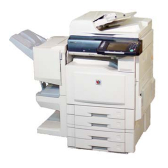
Page 48: External View
DP-C405/C305/C265 1.6. External View 1. Standard Configuration (For USA Only) Complies with FDA radiation performance standards, 21 CFR Subchapter J Manufacturer's Name and Address Factory ID Top View 32.5 in (826mm) 26.1 in (664 mm) Rear View Right View Left View Front View For USA, Canada and Europe For Other Destinations... - Page 49 DP-C405/C305/C265 2. With Optional System Console and Finisher Configuration 1-Bin Finisher (DA-FS402 / FS350 / FS320) Top View 14.84 in (377 mm) Left View Front View Right View Rear View 1-Bin Saddle-Stitch Finisher (DA-FS405 / FS356 / FS325) Top View 26.38 in (670 mm) Left View Front View...
- Page 50 DP-C405/C305/C265 3. Space Requirements With Options Main Unit 3.94 in (100 mm) 11.85 in 26.14 in (301 mm) (664 mm) 32.50 in (826 mm) 15.11 in (384 mm) 3.94 in (100 mm) 45.87 in (1165mm) Main Unit + Exit Tray (Outer) 3.94 in (100 mm) 3.46 in (88 mm)
- Page 51 Model Number and Destination Code (Main Unit) 3-Digit number or alphanumeric representation (Except Letters "I" and "O") For Example: (For USA and Canada) (For UK) = DP-C405-PU = DP-C405-PB = DP-C305-PU = DP-C305-PB = DP-C265-PB = DP-C265-PU = DP-C354-PU = DP-C354-PB = DP-C323-PU = DP-C323-PB...
-
Page 52: Control Panel
DP-C405/C305/C265 1.7. Control Panel Note 1: Model availability may differ as per destination. Please ask your sales company for details. Note 2: LCD Display Brightness Adjustment To adjust the brightness of the LCD display, press and while holding down the “Clear” key, keep pressing the “1”, or the “2”... -
Page 53: Fans
DP-C405/C305/C265 1.8. Fans Toner Bottle Fan IH Driver Fan Pressure Roller Fan IH Fan LVPS Fan Right Cover Fan LSU Fan 1.9. Motors ADF Paper Feed Motor ADF Feed Motor Scanning Motor Drum Motor 1 FTR and LSU Shutter Motor Fuser Motor Paper Transport Unit Motor... -
Page 54: Sensors
DP-C405/C305/C265 1.10. Sensors ADF Original Length Sensor 2 (401-03) Platen Cover (ADF) Angle Sensor (401-11) ADF Original Length Sensor 1 (401-04) Platen Cover (ADF) Open Sensor (401-12) ADF Original Width Sensor 2 (401-01) Fuser Unit Sensors (See Figure A) ADF Original Width Sensor 1 (401-02) Paper Path Sensor (ADU 0) (1819-38) ADF Exit Sensor (401-10) Inner Exit Sensor (1819-39) - Page 55 DP-C405/C305/C265 < Figure A > Fuser Pressure Release Sensor 1 (1819-17) IH Core Sensor 1 Fuser Pressure Release Sensor 2 (1819-16) (DP-C322 Series) IH Core Sensor 2 (DP-C322 Series) Thermistor (HR1) Fuser Entrance Sensor (1819-43) Thermistor (HR3) (DP-C322 Series) Thermistor (HR2) Thermistor (PR) (5031) Fuser Roller Rotating Encoder 1 (1819-19) Fuser Roller Rotating Encoder 2 (1819-18)
-
Page 56: Clutches And Switches
DP-C405/C305/C265 1.11. Clutches and Switches ADF Inverting Roller Clutch 2 Control Panel Power Switch ADF Inverting Roller Clutch 1 Right Upper Cover Interlock Switch 1 ADF Paper Feed Roller Clutch Right Upper Cover Interlock Switch 2 Right Upper Cover Detection Switch ADF Exit Roller Clutch ADF Registration Roller Clutch 1 2 WAY Ordinary Roller Clutch... -
Page 57: Disassembly Instructions
DP-C405/C305/C265 2 Disassembly Instructions 2.1. General Disassembly Pertinent Disassembly Instruction sections are shown below. i-ADF 2.2.1. STR Unit and Intermediate Transfer (IT) Unit Scanner Unit 2.2.10. 2.2.2. Process Unit Control Panel Unit 2.2.11. 2.2.3. Fuser Unit 2.2.12. 2.2.4. Paper Feed Module IH Unit 2.2.13. - Page 58 DP-C405/C305/C265 2.2. Disassembly Instructions 2.2.1. Inverting-Automatic Document Feeder (i-ADF) Unit (1) Lift the Original Tray Assembly. (2) Clean the Exit Roller (814). (3) Open the ADF Cover. (4) Clean the Pickup Roller (511), Paper Feed Roller (508), Separation Roller (610), and Registration Roller 1 (817) with a soft cloth, saturated with water.
- Page 59 DP-C405/C305/C265 (7) Remove the Paper Feed Roller Shaft Assembly by pulling in the arrow direction. (8) Remove the Paper Feed Roller (508). (9) Move the Pickup Bracket. (10) Remove 2 Snap Rings (H7). (11) Remove the Pickup Roller Shaft (510). (12) Remove the Pickup Roller (511).
- Page 60 DP-C405/C305/C265 (13) Remove 3 Screws (X8). (14) Remove the Lower Opening and Shutting Guide 1 (601). (15) Remove the Separation Roller Assembly. (16) Remove the Snap Ring (H6). Note: When reinstalling, make sure that the Snap Ring is installed properly as illustrated. Ver.
- Page 61 DP-C405/C305/C265 (17) Remove the Separation Roller Shaft (607). (18) Remove the Separation Roller (610). Note: When reassembling the Separation Roller, make sure that the Yellow Tooler's Die on the side of the roller is positioned as illustrated (facing the Front Frame).
- Page 62 DP-C405/C305/C265 (25) Remove 1 Screw (J2). (26) Loosen 3 Screws (S6). (27) Lift up the Original Tray Assembly. (28) Remove the ADF Rear Cover (627). (29) Remove 3 Screws (5M). (30) Remove the Front ADF Gear Bracket Assembly. (31) Remove the 16T Gear (825). (32) Remove 1 Screw (X5).
- Page 63 DP-C405/C305/C265 (34) Release the ADF Cover Arm (624). (35) Remove the ADF Cover Assembly. Note: When reinstalling the ADF Cover Assembly, make sure that the Vibration Guide Sheet 1 and 2 are reinstalled properly as illustrated. Note: When reinstalling the ADF Cover Assembly, make sure that the lever is positioned on the inside of the ADF Cover.
- Page 64 DP-C405/C305/C265 (38) Clean the Registration Roller 2 (818). (39) Remove the Snap Ring (G6). (40) Remove 1 Screw (X5). (41) Loosen 1 Screw. (42) Remove the Registration Limiter Bracket (829) as illustrated. (43) Remove the Limiter Joint (828). (44) Remove the Registration Roller Torque Limiter (827).
- Page 65 DP-C405/C305/C265 (46) Remove 2 Snap Rings (G6). (47) Remove the Clutch 1 (801). (48) Remove 2 D8 Bearings (822). (49) Remove the Registration Roller 2 (818). (50) Remove 2 Registration Guide Sheets 1 (1119), and 2 Registration Guide Sheets 2 (1120). Caution: Do not remove the illustrated 3 Screws.
- Page 66 DP-C405/C305/C265 Note: When reinstalling the Registration Guide Sheet 1 and 2, make sure that the Sheets are placed on the marks as illustrated. Mark Double Coated Registration Adhesive Tape Guide Sheet (51) Open the Lower Opening and Shutting Guide Assembly. (52) Lift the Original Tray Assembly.
- Page 67 DP-C405/C305/C265 (56) Remove 4 Screws (X5). (57) Remove the Lower Exit Guide (716). (58) Clean the Transport Roller (816). Ver. 1.1 FEB 2008...
-
Page 68: Scanner Unit
DP-C405/C305/C265 2.2.2. Scanner Unit (1) Open the ADF. <Cleaning the Scanner> (2) Clean the White Reference Sheet, and Scanning Pad with a soft cloth, saturated with isopropyl alcohol. (3) Clean the Scanning (S) Glass, and Platen (L) Glass with a soft cloth, saturated with isopropyl alcohol. - Page 69 DP-C405/C305/C265 (6) Remove the Glass Assembly. (7) Remove 1 Screw (X5). (8) Remove 2 Screws (X3). (9) Remove the Heat Sink Plate (1608). (10) Move the Scanning Lamp to a position where it can be easily replaced. (11) Remove 3 Screws (X5). (12) Release the Harness from the Clamp.
- Page 70 DP-C405/C305/C265 (14) Turn the Inverter PC Board Case upside down. (15) Disconnect the Flat Harness on the Inverter PC Board. (16) Remove the Inverter PC Board Assembly. (17) Disconnect the Lamp Harness. (18) Remove the Scanning Lamp (1615). (19) Remove 2 Screws (X8). (20) Remove the Inverter PC Board (1612).
- Page 71 DP-C405/C305/C265 <CCD Unit> (21) Remove 8 Screws (X5). (22) Remove the CCD Cover (1627). (23) Disconnect 2 Harnesses on the CCD PC Board. (24) Remove 2 Screws (Y23). (25) Remove the CCD Unit (1631). Important: Before proceeding, make a note of the position of the alignment pointer.
- Page 72 DP-C405/C305/C265 <AFE PC Board> (26) Remove 2 Screws (Y31). DP-C405 Series : PB and Other Destinations (Except PU / PT) (27) Remove 2 Metal Clamps on the AFE PC Board. (28) Disconnect all the Harnesses on the AFE PC Board. (29) Remove 4 Screws (Y31).
- Page 73 DP-C405/C305/C265 <Paper Size Sensor> (31) Remove 2 Screws (X5). (32) Disconnect 2 Harnesses from the Sensor. (33) Remove 2 Multi Beam Sensor 1 (1722). Note: 1. Do not touch the surface of the Sensors with your hands. 2. Clean any dirt or fingerprints with a Dry Cotton Swab.
- Page 74 DP-C405/C305/C265 (41) Clean the Mirror 1 (1602) with a soft cloth. Note: 1. Do not touch the surface of the Mirrors with your hands. 2. Clean any dirt or fingerprints with a Dry Cotton Swab. 3. Do not use Isopropyl Alcohol or any other Alcohol.
- Page 75 DP-C405/C305/C265 <Scanning Motor> (47) Remove 2 Screws (X5). (48) Remove the ADF Harness Holder (1517). (49) Disconnect the ADF Harness. Note: When reinstalling the ADF, take note of the connector position, and its keys. Insert it gently, and do not force the connector if it is facing the wrong way.
- Page 76 DP-C405/C305/C265 (56) Unhook, and remove the Motor Spring (1708). (57) Disconnect the Harness. (58) Remove 2 Screws (Y21). (59) Remove the Motor Bracket Assembly. (60) Remove the E-Ring (J7). (61) Remove the Reduction Gear (1711). (62) Remove 2 Screws (Y16). (63) Remove the Scanning Motor (1713).
- Page 77 DP-C405/C305/C265 <Home Position Sensor> (64) Disconnect the Harness. (65) Remove the Photo Sensor (401-13). <Platen Cover (ADF) Angle Sensor, Platen Cover (ADF) Open Sensor> (66) Disconnect the 2 Harnesses. (67) Remove 2 Photo Sensors (401-11, 401-12). Note: Ensure that the Sensor Harnesses are reinstalled properly as illustrated.
-
Page 78: Replacing The Battery
DP-C405/C305/C265 2.2.3. Control Panel Unit <Replacing the Battery> (1) Remove 1 Screw (X5). (2) Remove the Battery Holder (1306). (3) Replace the Battery (1330). (4) Reinstall the Battery Holder, and fasten it with 1 Screw. CAUTION Denotes hazards that could result in minor injury or damage to the machine. THIS PRODUCT CONTAINS A LITHIUM BATTERY. - Page 79 DP-C405/C305/C265 Avertissement CE PRODUIT CONTIENT UNE PILE AU LITHIUM. REMPLACEZ UNIQUEMENT AVEC LE MÊME TYPE DE PILE OU UN TYPE ÉQUIVALENT. UNE UTILISATION OU UN REMPLACEMENT IMPROPRE POURRAIT CAUSER UNE SURCHARGE, UNE RUPTURE OU UNE EXPLOSION RÉSULTANT EN DES BLESSURES OU UN INCENDIE.
- Page 80 DP-C405/C305/C265 For PB and Other Destinations (10) Remove 2 Screws (X5). (11) Adjust the Control Panel to the 2nd position. (12) Unhook, and remove the Damper Spring (1208). (13) Remove the Control Panel Unit by pulling the Release Lever as illustrated. (14) Disconnect the Harnesses on the PNL1 PC Board.
- Page 81 DP-C405/C305/C265 (15) Turn the Control Panel Unit upside down. (16) Remove 1 Screw (X8). (17) Remove the Battery Holder (1306). (18) Remove 1 Screw (X5). (19) Remove the Release Lever (1305). (20) Remove 2 Screws (X1). (21) Remove the Lower Panel Cover (1304). (22) Release the Harnesses from the 2 Harness Clamps.
- Page 82 DP-C405/C305/C265 (30) Remove 1 Screw (X8). (31) Remove the PNL 4 PC Board (1333). (32) Remove 2 Screws (X8). (33) Remove the PNL 3 PC Board (1332). (34) Remove 4 Screws (X8). (35) Remove the PNL 2 PC Board (1331). (36) Remove 4 Screws (X8).
- Page 83 DP-C405/C305/C265 (40) Disconnect the Harness on the SDI PC Board. (41) Remove 4 Screws (X5). (42) Remove the SDI Cover (1203), and SDI PC Board (1217). Ver. 1.1 FEB 2008...
-
Page 84: Fuser Unit
DP-C405/C305/C265 2.2.4. Fuser Unit (1) Open the Right Side Upper Cover. (2) Remove 1 Screw (X5). (3) Remove the Harness Cover 2 (4813). (4) Disconnect the Harness. (5) Loosen 2 Screws. (6) Remove the Fuser Unit (4815). Ver. 1.1 FEB 2008... - Page 85 DP-C405/C305/C265 (7) Unhook 2 Pressure Springs (5006). Caution: Don't use a plier for unlocking the Springs, Not to damage the spring. Ensure the Pressure Springs are unlock position when replace the Fuser Belt Unit. Caution: To unlock the Pressure Springs: Press the Energy Saver , and then turn off the Power Switch on the Left side of the machine.
- Page 86 DP-C405/C305/C265 (11) Remove 3 Black Screws (Y41). (12) Remove the Shaft Plate (4916). (13) Remove the worn-out Fuser Belt Unit (4926). <For DP-C322 Series> (16) Remove 1 Black Screw (Y41). (17) Remove the Harness Cover 3 (4921). (18) Disconnect 3 Harnesses. Ver.
- Page 87 DP-C405/C305/C265 (19) Remove 3 Black Screws (Y41). (20) Remove the Shaft Plate (4916). (21) Remove 3 Black Screws (Y41). (22) Remove the Shaft Plate (4916). (23) Disconnect 2 Harnesses. (24) Remove the worn-out Fuser Belt Unit (4926). Ver. 1.1 FEB 2008...
- Page 88 DP-C405/C305/C265 <Replacing the Fuser Belt Unit (4926) > (25) Remove all the tapes, and shipping material from the new Belt Unit. (26) Remove the 2 Bands. (27) Remove the Protective Paper, and Shipping Materials. (28) Remove 2 Pins. (29) Install the New Fuser Belt Unit on the Fuser Main Unit.
- Page 89 DP-C405/C305/C265 <For DP-C405 / C354 Series> Follow the steps below <For DP-C322 Series> Skip to step (39) (31) Reinstall 2 Black Screws. (32) ReInstall the Shaft Plate. (33) Reinstall 1 Black Screw. (34) Reinstall 2 Black Screws. (35) Reinstall the Shaft Plate. (36) Reinstall 1 Black Screw.
- Page 90 DP-C405/C305/C265 Note: When connecting, exercise care not to touch the Fuser Belt. Note: Ensure that the Harnesses are reinstalled properly as illustrated. <For DP-C322 Series> (39) Reinstall 2 Black Screws. (40) ReInstall the Shaft Plate. (41) Reinstall 1 Black Screw. (42) Reinstall 2 Black Screws.
- Page 91 DP-C405/C305/C265 (45) Connect 2 Harnesses. Note: Ensure that the Sensor Harnesses are reinstalled properly as illustrated. Red Harness : “R” Carved Sensor Black Harness : “BK” Carved Sensor (46) Remove the Shipping Cover. (47) Connect the 3 Harnesses. Note: When connecting, exercise care not to touch the Fuser Belt.
- Page 92 DP-C405/C305/C265 Note: Ensure that the Harnesses are reinstalled properly as illustrated. (48) Reinstall the Harness Cover 3 (4921). (49) Reinstall 1 Black Screw. <Install the Fuser Unit> (50) Install the Fuser Unit. (51) Secure 2 Screws. (52) Connect the Harness. (53) Reinstall the Harness Cover 2 (4813).
- Page 93 DP-C405/C305/C265 (58) Remove the Protective Paper, and Shipping materials. <Installing the Complete Fuser Unit> See the installation steps in this section. Note: When reinstalling the Complete Fuser Unit, reset the PM Counter. Perform “F8-26” Fuser Belt Counter Reset, and “F8-27” Fuser Main Counter Reset. (F7-02-65/85/ 86 Fuser Belt Remain Count, and F7-02-66/87/88 Fuser Main Remain Count are also initialized by this operation)
- Page 94 DP-C405/C305/C265 2.2.5. IH Unit (1) Remove 11 Screws (S6). (2) Remove the Rear Cover Assembly. (3) Remove 1 Screw (Y31). (4) Remove the CONE PC Board (3922). <Removing the SC PC Board Assembly> For DP-C405 Series PU / For DP-C354/C322 Series Follow steps (5) - (8) (5) Disconnect all the Harnesses on the SC PC Board (6401).
- Page 95 DP-C405/C305/C265 (10) Remove 1 Screw (X5), and Harness with the Metal Clamp. (11) Disconnect all the Harnesses on the SC PC Board (6401). (12) Remove the Harnesses from 4 Clamps. (13) Remove 13 Screws (X5). (14) Remove the SC PC Board Assembly by lifting, and turning to the left as illustrated.
- Page 96 DP-C405/C305/C265 (18) Disconnect all the Harnesses on the MOTDRV PC Board (6504). (19) Remove the Fan Harness from 2 Clamps. (20) Remove 2 Screws (X5). (21) Remove the IH Fan Assembly. (22) Remove 5 Screws (X5). (23) Remove the IH PCB Bracket (4004). (24) Remove 2 Screws (X5).
- Page 97 DP-C405/C305/C265 (27) Remove the Harness from 3 Mini Clamps, and 6 Clamps. (28) Remove 2 Screws. (29) Remove the Right Side Rear Cover (205). (See sect. 2.2.6.) (30) Open the Right Side Upper Cover. (See sect. 2.2.4.) (31) Remove the Fuser Unit. (See sect. 2.2.4.) (32) Remove 2 Screws (S6).
- Page 98 DP-C405/C305/C265 (35) Remove the Harness from 6 Clamps. <The Paper Transport Unit Option is installed> 1. Remove 5 Screws (X5, X9, Y46). 2. Remove the Bracket Assembly by lifting up the Paper Transport Unit. 3. Remove 1 Screw (X5) by pushing the Flap downward as illustrated.
- Page 99 DP-C405/C305/C265 6. Remove the Paper Transport Unit by pulling the Lock Lever as illustrated. (36) Remove 4 Screws (X5). (37) Remove the Paper Exit Unit. (38) Pull Tray 1, and Tray 2 half way out. (39) Open the Front Cover. (See sect. 2.2.11.) (40) Remove 2 Screws (Y13).
- Page 100 DP-C405/C305/C265 (42) Remove 2 Screws (S6). (43) Release the Lever Arm. (44) Unlock 2 Front Cover Attachment Pins (220) by turning them in the upward direction, and sliding to the right. (45) Remove the Front Cover. (46) Remove 2 Screws (S6). (47) Remove the Inner Rear Cover (201).
- Page 101 DP-C405/C305/C265 (50) Remove 4 Screws (S6). (51) Remove the Front Right Cover (209) by releasing the Latch on the Exit Cover (202). (52) Loosen 1 Thumb Screw. (53) Remove 1 Screw (S6). (54) Lift the Scanner Unit slightly, and remove the Exit Cover (202).
- Page 102 DP-C405/C305/C265 (56) Remove 2 Screws (X5). (57) Remove the IH Unit. Caution: When removing the IH Unit, pull it out gently. To prevent damaging the Harness, carefully guide it throughout the side of the frame. Ver. 1.1 FEB 2008...
- Page 103 DP-C405/C305/C265 <Remove the IH Brackets> Remove 2 Screws from both sides. Caution: When reinstalling the IH Unit, make sure that the IH Fan Duct is positioned inside of the IH Sheet. Ver. 1.1 FEB 2008...
- Page 104 DP-C405/C305/C265 2.2.6. Auto Duplex Unit (ADU) (1) Open the Jam Cover. (2) Open the Sheet Bypass Tray. (3) Remove 2 Screws (S6). (4) Remove the Right Side Front Cover (206). (5) Remove 3 Screws (S6). (6) Remove the Right Side Rear Cover (205). (7) Open the Upper Right Side Cover.
- Page 105 DP-C405/C305/C265 (8) Disconnect 3 Harnesses on the ADU PC Board (CN403, CN404, CN405) (9) Release 3 Harnesses from the Edge Saddle. (10) Remove the Lower Dumper Bracket (2114). (11) Remove the Dumper (2116). (12) Open the Lower Right Side Cover. (13) Remove 1 Snap Ring (G6).
- Page 106 DP-C405/C305/C265 (15) Remove the ADU. Note: When reinstalling the ADU, make sure that the Harnesses are reinstalled properly as illustrated. (16) Remove 1 Screw (X5). (17) Remove the Exit Guide Bracket (2308). Ver. 1.1 FEB 2008...
- Page 107 DP-C405/C305/C265 (18) Remove 1 Screw (X5). (19) Remove the Exit Guide Bracket (2308). (20) Remove 3 Screws (X8). (21) Remove the Guide Cover (2307). <Paper Path Sensor (ADU0)> (22) Disconnect the Harness. (23) Remove the Photo Sensor (1819-38) Assembly. (24) Remove 3 Screws (X8). (25) Remove the ADU Upper Guide (2207).
- Page 108 DP-C405/C305/C265 <Cleaning the ADU 1st Roller> Clean the ADU 1st Roller with a soft cloth, saturated with water. (26) Remove 1 Screw (X3). (27) Remove the Cover Knob (2202). (28) Remove 9 Screws (X8). (29) Remove the Coating Clip (2219). Ver.
- Page 109 DP-C405/C305/C265 (30) Remove the Harness Clamp (2218). Note: Make sure to reinstall the Harness Clamp properly as illustrated. (31) Remove the ADU Cover (2201). (32) Remove 5 Screws (X8). (33) Remove the Cover Plate (2203). (34) Remove the Spring Ground (2208). Ver.
- Page 110 DP-C405/C305/C265 (35) Remove 1 E-Ring (J7). (36) Remove the Latch (2210). (37) Remove the Left Latch Spring (2211). (38) Remove the Bushing (2213). (39) Remove the Latch Lever Shaft (2209) Assembly. (40) Release the Harness from the Clamps. (41) Remove 2 Screws (X4). (42) Remove the Right Cover Fan (2214).
- Page 111 DP-C405/C305/C265 Note: When reinstalling the Cover, make sure that the harness band is reinstalled properly as illustrated. Ver. 1.1 FEB 2008...
- Page 112 DP-C405/C305/C265 2.2.7. Paper Exit Transportation (1) Open the Right Side Upper Cover. (See sect. 2.2.4.) (2) Remove the Fuser Unit. (See sect. 2.2.4.) (3) Remove 2 Screws (S6). (4) Remove the Top Cover (207). (5) Disconnect 2 Harnesses on the ADU PC Board (CN401, and CN402), and the intermediate connector.
- Page 113 DP-C405/C305/C265 (10) Move the Paper Transport Unit slightly to the left by pulling the lock lever as illustrated. (11) Remove the Paper Exit Unit (see the previous step). <Paper Full Sensor> (12) Remove 1 Screw (X5). (13) Disconnect the Harness. (14) Remove the Photo Sensor (1918-02).
- Page 114 DP-C405/C305/C265 (20) Remove the Arm Spring (3227). (21) Remove 2 Screws (X5). (22) Remove 2 Screws (Y16). (23) Remove the Clutch Bracket (3226). (24) Remove the D Z27M1 Gear (3224). (25) Remove the Clutch Shaft (3225). <Inner Exit Sensor> (26) Remove 2 Screws (X5). (27) Remove the Sensor Cover Assembly.
- Page 115 DP-C405/C305/C265 <Cleaning the Exit Roller> (30) Remove 1 Screw (Y1). (31) Remove the Exit Guide (227). (32) Clean the Exit Roller (3302), and Upper Pinch Roller (3208), Lower Pinch Roller (3301) with a soft cloth, saturated with water. Ver. 1.1 FEB 2008...
- Page 116 DP-C405/C305/C265 2.2.8. Lower Right Side Cover Unit (1) Remove the Right Front Cover (See sect. 2.2.6.) (2) Remove the Right Rear Cover (See sect. 2.2.6.) (3) Remove the Sheet Bypass Tray Cover. (See sect. 2.2.9.) (4) Open the Lower Right Side Cover. (See sect.
- Page 117 DP-C405/C305/C265 <Cleaning the OHP Detection Reflector> Clean the OHP Detection Reflector with a soft cloth, saturated with isopropyl alcohol. Note: When reinstalling the Lower Right Side Cover Unit, pull the lock lever to the locked position in the direction illustrated by the arrow. (10) Remove 3 Screws (X5).
- Page 118 DP-C405/C305/C265 (13) Disconnect the Harness. (14) Remove 1 Screw (Y24). (15) Remove the Sensor Bracket (2825) Assembly. <Right Cover Open Sensor> (16) Remove the Photo Sensor (1819-06). (17) Remove 2 Screws (Y16). (18) Remove Guide Bracket Assembly. (19) Remove the STR Unit (2535) as illustrated. Ver.
- Page 119 DP-C405/C305/C265 (20) Remove 1 Screw (X8). (21) Remove the Plate Cover Bracket (2734). (22) Turn the Lower Right Side Cover Unit upside down. Note: Before turning the Unit upside down, make sure to remove the STR Unit, or the STR may get damaged.
- Page 120 DP-C405/C305/C265 (27) Remove 2 Screws (X8). (28) Remove the ADU Guide 2 (2824). (29) Disconnect the Harness. (30) Release the Harness from 2 latches. (31) Remove 2 Screws (X8). (32) Remove the ADU Sensor Base (2821) Assembly. <Paper Path Sensor (ADU2)> (33) Remove the Photo Sensor (1819-07).
- Page 121 DP-C405/C305/C265 (34) Disconnect the Harness on the ADU PC Board (CN407). (35) Remove 4 Screws (X5). (36) Remove the Registration Unit. <Cleaning the Registration Sensor 2 and Intermediate Roller Sensor (DP-C405 / C305 Only)> Clean the Registration Sensor 2 (1918-01) and Intermediate Roller Sensor (2130) with a Dry Cotton Swab.
- Page 122 DP-C405/C305/C265 (39) Disconnect the Harness on the ROHP PC Board. (40) Remove 2 Screws (F10). (41) Remove the ROHP PC Board (2110). (42) Disconnect 2 Harnesses. (43) Remove the Harness from 2 Clamps. (44) Remove 2 Screws (F10). (45) Remove the RI Sensor Plate (2131). For DP-C265, DP-C354 / C322 Series Follow steps (46) - (48) (46) Disconnect the Harness.
- Page 123 DP-C405/C305/C265 2.2.9. Sheet Bypass Unit (1) Open the Jam Cover. (See sect. 2.2.6.) (2) Open the Sheet Bypass Tray. (See sect. 2.2.6.) (3) Remove the Right Front Cover. (See sect. 2.2.6.) (4) Remove the Right Rear Cover. (See sect. 2.2.6.) (5) Remove the Sheet Bypass Tray Cover (2918) as illustrated.
- Page 124 DP-C405/C305/C265 (10) Lift the Sheet Bypass Tray as illustrated. (11) Remove the Tray Spring (2916). (12) Remove 1 Screw (X8). (13) Remove the Tray Plate Shaft (2917). (14) Remove the Tray Assembly. Note: When removing the Tray Assembly, carefully separate as illustrated. (15) Turn the Sheet Bypass Assembly upside down as illustrated.
- Page 125 DP-C405/C305/C265 (19) Remove 2 Screws (X8). (20) Remove the Arm Bracket Assembly. (21) Remove the DFP Roller (3111). <Cleaning DFP Roller> Clean the DFP Roller with a soft cloth, saturated with water. (22) Remove 3 Screws (X5). (23) Remove the Upper Plate (3008). (24) Remove 1 Screws (X5).
- Page 126 DP-C405/C305/C265 (26) Remove 2 Snap Rings (H6). (27) Remove 2 Stoppers (3007). (28) Remove 2 Spacers (3006). (29) Remove the Front Pickup Roller (3005). (30) Remove the Rear Pickup Roller (3012). <Cleaning Pickup Roller> Clean the Pickup Roller with a soft cloth, saturated with water.
- Page 127 DP-C405/C305/C265 2.2.10. STR Unit and Intermediate Transfer (IT) Unit (1) Open the Sheet Bypass Tray. (2) Open the Lower Right Side Cover. (3) Remove 2 Screws (Y16). (4) Remove the Guide Bracket Assembly. (5) Remove the STR Unit (2535). (6) Remove the Snap Ring (2714). (7) Remove the Support Arm Assembly.
- Page 128 DP-C405/C305/C265 (8) Push on the STR Guide to lock it in the down position. (9) Remove 2 Screws (Y45). <Pulling out the Intermediate Transfer (IT) Unit> (10) Push down the white latches on both sides, and pull on them to release the IT Unit from the locked position.
- Page 129 DP-C405/C305/C265 (12) While holding the IT Unit on both sides, release the lock by pushing the lever to the right. (13) Carefully pull the IT Unit (3420) out of the machine while holding it by both sides. Caution: Pull the IT Unit out straight and leveled (horizontal), or the IT Belt may get damaged, and the printing quality will be affected.
- Page 130 DP-C405/C305/C265 <Cleaning the Toner Density Registration Sensor, and the Toner Registration Sensor (Right/Left)> (15) Slide the Sensor Cover toward the front as illustrated. (16) While holding it in the open position, wipe the surface of the Toner Registration, and Toner Density Sensors through the frame holes.
- Page 131 DP-C405/C305/C265 (24) Unhook 4 Link Arm Springs (3408). (25) Set 4 Link Arms to the locked position as illustrated. (26) Remove 4 Black Screws (Y29) from the right side. Ver. 1.1 FEB 2008...
- Page 132 DP-C405/C305/C265 (27) Remove 4 Black Screws (Y29) from the left side. (28) Remove the Handle Plate Bracket Assembly. Caution: When Removing and Installing the Handle Plate Bracket Assembly, hold both side of the Bracket as illustrated, and don’t touch the IT Belt. (29) Remove 1 Black Screw (Y29).
- Page 133 DP-C405/C305/C265 (33) Place the IT Unit on its side with the side that has the belt position mark facing upward. (34) Bend the IT Unit at the bending point up to maximum bending position. Caution: Confirm that the IT Unit is at the maximum bending position for removing the IT Belt.
- Page 134 DP-C405/C305/C265 (37) Remove 4 Snap Rings (3545) securing the FTR by turning over the Protect Sheet as illustrated. Note: When removing snap rings, exercise care not to remove the Snap Ring holding the Backup Roller. (38) Remove 4 FTR (3546) by turning over the Protective Sheet as illustrated.
- Page 135 DP-C405/C305/C265 (41) Remove 2 Black Screws (Y29). (42) Remove the Drive Roller Brush Assembly (3635). <Cleaning the Bias Roller, Initial Point Sensor Roller, Adjustment Roller, and Drive Roller> (43) Clean the Bias Roller, Initial Point Sensor Roller, Adjustment Roller, and Drive Roller with a soft cloth, saturated with isopropyl alcohol, and then wipe them with a soft dry cloth.
- Page 136 DP-C405/C305/C265 (46) Remove 2 Adjust Bushings (3419). Note: Use the Adjustment Bushings enclosed with the new IT Belt to accommodate for the belt length variations. (47) Install 1 (new) Adjustment Bushing (3419) to the Right Side. (48) Install 1 (new) Adjustment Bushing (3419) to the Left Side.
- Page 137 DP-C405/C305/C265 Note: When reinstalling the Snap Ring, use a pair of pliers as illustrated. (50) Reinstall the 4 FTR. Note: Reinstall the FTR by turning over the Protective Sheet. Note: When reinstalling the FTR, the direction is not critical, and it can be installed in either direction as illustrated.
- Page 138 DP-C405/C305/C265 Caution: When Removing and installing the IT Belt, hold the side band of the IT Belt as illustrated. Don’t touch the center of the belt, or the printing quality will be affected. Caution: When installing the IT Belt, align the position of roller steps, and belt projections as illustrated.
- Page 139 DP-C405/C305/C265 (53) Straighten the IT Unit to its original shape as illustrated. Note: Take your time during the installation, and proceed cautiously. (54) Reinstall the Left Position Plate. (55) Reinstall the Handle Plate Bracket Assembly. (56) Hook 4 Springs. (57) Reinstall the Upper Paper Guide. (58) Reinstall the Lower Paper GUide.
- Page 140 DP-C405/C305/C265 (62) Using a pair of pliers as illustrated, reinstall the Left Position Plate (3416). (63) Reinstall 1 Black Screw (Y29). (64) Reinstall the Handle Plate Bracket Assembly. (65) Reinstall 4 Black Screws (Y29) from the left side. Caution: When Removing and Installing the Handle Plate Bracket Assembly, hold both sides of the Bracket as illustrated, and don’t touch the IT Belt.
- Page 141 DP-C405/C305/C265 (67) Release 4 Link Arms from the locked position as illustrated. (68) Hook 4 Link Arm Springs (3408). (69) Reinstall the Upper Paper Guide (3411). (70) Reinstall 2 Black Screws (Y29). (71) Reinstall the Lower Paper Guide (3412). (72) Reinstall 2 Black Screws (Y29). Ver.
- Page 142 DP-C405/C305/C265 (73) Reinstall the Cleaning Unit (3418). (74) Reinstall 2 Black Screws (Y29). <Reinstalling the IT Unit> (75) Maintain the IT Unit leveled by holding it on both sides while installing it into the machine. Note: When installing, ensure that the STR Bracket locks in place.
- Page 143 DP-C405/C305/C265 (77) Unlock the STR Guide. Caution: When unlocking, exercise care not to pinch your fingers with the STR Guide. (78) Install the STR Unit. Note: During the installation ensure that the hook is properly attached. (79) Reinstall the Guide Bracket. Note: When reinstalling, make sure that the convex is in the hole as illustrated.
- Page 144 DP-C405/C305/C265 2.2.11. Process Unit <Replacing the Developer Unit > <Replacing the Developer Unit> Note: The procedure below describes how to replace the Developer Unit for the Cyan Color. (1) Open the Front Cover. Caution: When the windows shown by the arrow are Yellow, close all of the doors, and turn the Main Power Switch OFF, and ON again.
- Page 145 DP-C405/C305/C265 (5) Unlock the Drum Units (Cyan and Magenta) by turning the Drum Release Knob counterclockwise. Note: To remove the Hopper Unit in Step 16, the Drum Unit(s) relevant to the Developer Unit being replaced must be unlocked, and removed first. (See the Table below) Developer Unit Unlock...
- Page 146 DP-C405/C305/C265 (8) Remove 2 Screws (Y13). (9) Remove the Inner Stack Cover (203). <Cleaning the Toner Supply Cylinder> (10) Clean the Toner Supply Cylinder with a Vacuum cleaner. (11) Remove 6 Screws (Y33). (12) Remove the Pipe Cover (4421). (13) Place a clean sheet of paper (i.e. Ledger or A3) on top of the Front Cover to catch any toner spill.
- Page 147 DP-C405/C305/C265 (14) Lock the Drum Unit by turning the Drum Release Knob clockwise. Note: This step eases the removal of the Hopper Unit in the next step. (15) Remove 1 Screw (Y13). (16) Remove the Hopper Unit as illustrated. Note: Pull the bottom portion out by clasping with the left forefinger.
- Page 148 DP-C405/C305/C265 (18) Clean the Toner Entrance with a Vacuum cleaner. (19) Release the Lever Arm. (20) Remove 2 Screws (Y1). (21) Remove the WTC Lower Cover (4401). (22) Release 2 Harness Clamps. (23) Disconnect the Developer Harness. Ver. 1.1 FEB 2008...
- Page 149 DP-C405/C305/C265 (24) Remove 3 Screws (X5). (25) Remove the Developer Front Bracket (4422). <Cleaning the Developer Cover> (26) Clean the Developer Front Bracket (4422) with a Vacuum cleaner. (27) Pull the Developer Unit (Cyan) (5443) out. Note: Do not open the shutter, or Toner will spill out. Note: Ensure the Lever Arm is at the maximum down position, or Drum may get damaged.
- Page 150 DP-C405/C305/C265 (30) Gently peel the Tape off in the direction of the arrow. (31) Remove 2 Screws (X8). (32) Remove the Developer Cover (5401) by releasing 4 latches. <Replacing the Developer> Note: Only if a problem occurs, perform the step below. If there is no problem, skip to the step (34).
- Page 151 DP-C405/C305/C265 (34) Shake the Developer Bottle a few times to loosen its contents. (35) Carefully pour the developer evenly into the developer unit while turning the Gear as illustrated. Make sure to empty the bottle. (36) Reinstall the Developer Cover. (37) Install the new Developer Unit.
- Page 152 DP-C405/C305/C265 (41) Reinstall the Hopper Unit. Note: 1. When reinstalling, make sure that the 2 projections on the Hopper Unit are seated in the 2 Holes firmly, and at the same time, the supply cylinder is properly positioned as illustrated. 2.
- Page 153 DP-C405/C305/C265 (50) Turn the Toner Cartridge upside down as illustrated, then reinstall the Toner Cartridge. (51) Reinstall the Toner Waste Container. <Resetting the PM Counters> Note: Do not close the Front Cover. (52) Plug the AC Power Cord. (53) Turn the Main Power Switch on the Back, and the Power Switch on the Left Side of the machine to the ON position.
- Page 154 DP-C405/C305/C265 2.2.12. LSU (1) Open the Front Cover. (2) Pull the 2nd Paper Tray out. (3) Remove 5 Screws (S6). (4) Remove the Left Cover. For DP-C405 Series : PB and Other Destinations (5) Loosen 4 Screws. (6) Remove the Bracket. Caution: Gasket Hole...
- Page 155 DP-C405/C305/C265 (7) Remove 1 Screw (Y45). (8) Remove the Ground Harness. (9) Remove 1 Screw (Y33). (10) Remove the LSU Fan (4302). (11) Disconnect 3 Harnesses on the LSU PC Board. Important: Before proceeding, make a note of the alignment pointer position.
- Page 156 DP-C405/C305/C265 2.2.13. Paper Feed Module (1) Remove the Sheet Bypass Tray. (See sect. 2.2.9.) (2) Remove the Lower Right Side Cover Unit. (See sect. 2.2.8.) (3) Disconnect the Harness on the ADU PC Board (CN408, CN409). (4) Release the Harness from 2 Clamps. (5) Pull the 1st Paper Tray out.
- Page 157 DP-C405/C305/C265 (8) Remove the Snap Ring (H7), and Pickup Roller (1926) while pushing the solenoid as illustrated to lift the shaft of the Pickup Roller, for easy removal. <Cleaning the Pickup Roller> Clean the Pickup Roller surface with a soft cloth, saturated with water.
- Page 158 DP-C405/C305/C265 (13) Remove the Bushing (1915). (14) Remove the One Way Clutch (1923). (15) Remove the Feed Roller (1922). <Cleaning the Feed Roller> Clean the Feed Roller with a soft cloth, saturated with water. (16) Disconnect the Harnesses. (17) Remove 2 Sensors (401-14, 401-15).
- Page 159 DP-C405/C305/C265 (20) Disconnect the Harness. (21) Remove 1 Screw (Y19). (22) Remove the 2nd Paper Feed Module. Note: Follow the instructions of steps (8) - (17) for the 1st Paper Feed Module. <Cleaning the Intermediate Roller> (23) Remove the Sheet Bypass Tray. (See sect.
- Page 160 DP-C405/C305/C265 2.2.14. System Console (1) Open the Jam Cover. (2) Pull the 3rd Paper Tray out. (3) Remove 2 Screws (S6). (4) Remove the Right Side Rear Cover (6704). (5) Remove 1 Screw (Y19). (6) Remove the Cover Belt (6715). (7) Remove the Jam Cover while pushing the release button.
- Page 161 DP-C405/C305/C265 (8) Disconnect the Harness. (9) Release the Harness from the clamp. (10) Remove 1 Screw (Y19). (11) Remove the 3rd Paper Feed Module. Note: Follow the instructions for steps (8) - (17) of the 1st Paper Feed Module. (See sect. 2.2.13.) (12) Pull the 4th Paper Tray out.
- Page 162 DP-C405/C305/C265 (15) Remove 1 Screw (Y19). (16) Remove the 4th Paper Feed Module. Note: Follow the instructions for steps (8) - (17) for the 1st Paper Feed Module. (See sect. 2.2.13.) <Cleaning the Intermediate Roller> (17) Open the Jam Cover. (18) Clean the 3rd/4th Intermediate Roller with a soft cloth, saturated with water.
- Page 163 DP-C405/C305/C265 2.2.15. PC Boards, HVPS, HDD (1) Remove 11 Screws (S6). (2) Remove the Rear Cover Assembly. (3) Remove 1 Screw (Y31). (4) Remove the CONE PC Board (3922). (5) Disconnect all Harnesses on the SC PC Board. (6) Remove 10 Screws (Y31). (7) Remove the SC PC Board (6401).
- Page 164 DP-C405/C305/C265 (11) Remove 3 Screws (X5). (12) Remove the Left EC PCB Bracket (3909). For DP-C405 Series : PU Follow steps (13) - (15) (13) Remove the Harnesses from all Clamps on the SC PCB Bracket (3901). (14) Remove 12 Screws (X5). (15) Remove the SC PCB Bracket (3901).
- Page 165 DP-C405/C305/C265 For DP-C354 / C322 Series Follow steps (20) - (24) (20) Remove the Harnesses from all Clamps on the SC PCB Bracket (3901). (21) Remove 12 Screws (X5). Note: For PB and Other Destinations Remove the additional 13th Screw (X5), illustrated as Screw A.
- Page 166 DP-C405/C305/C265 (29) Remove 7 Screws (X5). (30) Remove the EC PCB Bracket (3908). (31) Disconnect all Harnesses on the HVPS2 PC Board. (32) Remove 8 Screws (Y31). (33) Remove the HVPS2 PC Board (4015). (34) Remove 3 Screws (X5). (35) Pull the HVPS1 PC Board Assembly out. Ver.
- Page 167 DP-C405/C305/C265 (36) Remove 12 Screws (X5). (37) Remove 2 HVPS1 PC Boards (4014). (A) : For Yellow / Magenta (B) : For Cyan / Black (38) Remove 4 Screw (X5). (39) Pull the HVPS2 PCB Bracket (4003) out. <Removing the Motor Assemblies> (40) Open the Front Cover.
- Page 168 DP-C405/C305/C265 (45) Disconnect the Harness on the Motor PC Board Assembly. (46) Remove 3 Screws (X5). (47) Remove the Motor Assembly. Note: These procedures are for Motor Assemblies No. 1 (5901), No. 3 (5903), No. 4 (5905), and No. 6 (6126) shown in the illustration of step (44).
- Page 169 DP-C405/C305/C265 (51) Disconnect all the Harnesses on the MOTDRV PC Board. (52) Release 3 PCB Spacers (4006). (53) Remove the MOTDRV PC Board (6504). (54) Release the Harness from 2 Clamps. (55) Remove 2 Screws (X5). (56) Remove the Fan Assembly. (57) Remove 5 Screws (X5).
- Page 170 DP-C405/C305/C265 (60) Remove 3 Screws (X5). (61) Release 2 PCB Spacers (4016). (62) Remove the IH PC Board (4020). <Removing the Hard Disk Drive Unit (DP-C405 Series Only)> (63) Remove the DC12 Harness and the SATA Harness from Harness Clamps. (64) Disconnect the HD2 Harness from the HDD Connector.
- Page 171 DP-C405/C305/C265 (71) Remove the DC12 Harness and the HD2 Harness from Harness Clamps. (72) Disconnect the DC12 Harness on the DC12 PC Board (CN141 and CN142). (73) Disconnect the HD2 Harness on the DC12 PC Board (CN143). Caution: When reinstalling 2 Harnesses, the Tie Wrap should be located on the right side of the Harness Clamp as illustrated.
- Page 172 DP-C405/C305/C265 2.2.16. Drive Unit (1) Open the Front Cover (2) Remove the Toner Waste Container. (3) Pull all the Drum Units out approximately 20 mm (0.79 in). (4) Remove the 2 Screws (X5). (5) Remove the SC Support Bracket (3903). (6) Release the Harnesses from 11 Clamps, and the Drive Unit.
- Page 173 DP-C405/C305/C265 (9) Remove 7 Screws (X5). (10) Remove 1 Screw (Y30). (11) Remove the Gear Box Cover (5912). (12) Remove 4 Snap Rings (H6). (13) Remove the E-Ring (J6). (14) Remove 6 FTR Coupling Gears (5906). Caution: When reinstalling, align the Gear holes and Frame holes as illustrated.
- Page 174 DP-C405/C305/C265 (18) Remove the Belt (6130). (19) Remove the Upper Gear (6131). (20) Remove the Upper Clutch (6129). (21) Remove the Lower Gear (6131). DP-C405 / C305 Only (22) Remove the Lower Clutch (6128). (23) Release the Harness from Harness Clamp. (24) Disconnect the Motor Harness.
- Page 175 DP-C405/C305/C265 (31) Disconnect the Lift Up Motor Harness on the SC PCB. (32) Release the Harness from 2 Harness Clamps. (33) Remove 3 Screws (X5). (34) Remove the Lift Up Motor Assembly. (35) Remove 2 Screws (X5). (36) Remove the Lift Up Motor Bracket Assembly. (37) Remove 2 Photo Sensors (1819-04, 1819-05).
- Page 176 DP-C405/C305/C265 2.2.17. LVPS Unit (1) Remove the Rear Cover Assembly. (See sect. 2.2.15.) (2) Disconnect 5 Harnesses; (CN52, and CN53) on the SC PCB, (CN519, and CN520) on the EC PCB, and the Intermediate Connector. (3) Release the Harnesses from 14 Harness Clamps.
- Page 177 DP-C405/C305/C265 (10) Disconnect the Harness. (11) Remove 2 Screws (X5). (12) Remove the NFL PCB Assembly (4116). (13) Release the Harnesses from the Edge Saddle. (14) Remove 2 Screws (X5). (15) Remove the LVPS Duct Cover (4106). (16) Release the Harnesses from Harness 5 Clamps.
- Page 178 DP-C405/C305/C265 (17) Remove 6 Screws (X5). (18) Remove 3 Screws (Y16). (19) Remove the LVPS Bracket (4102). (20) Disconnect the Fan Harness. (21) Release the Harness from Harness Clamp. (22) Remove 2 Screws (4104). (23) Remove the LVPS Fan (4103). (24) Disconnect all the Harnesses on the LVPS.
-
Page 179: Hardware Identification Template
DP-C405/C305/C265 2.3. Hardware Identification Template Ref. No. Part No. Figure Remark XTB3+12GFJ Screw (M3 x 12) XYN3+F4FJ Screw (M3 x 4) FFPFJ0039B Snap Ring XTB4+10GFN Silver Screw FFPFJ0033B Snap Ring FFPFJ0041B Snap Ring FFPFA01632 Shoulder Screw XTT4+8HFN Silver Screw XUC3VM E-Ring XUC4VM E-Ring... - Page 180 DP-C405/C305/C265 Ref. No. Part No. Figure Remark XTW3+8PFJ Screw (M3 x 8) XTW4+10PFJ Screw (M4 x 10) DZPA000098 Shoulder Screw DZPA000086 Screw XTB3+10GFJ Screw XYN3+F8FJ Screw XTB3+20GFJ Screw XTB3+6FFJ Screw XTB3+8GFJ Screw XTB3+8FFJ Screw XTW3+8PFJ Screw XTB3+6FFJ-RP Screw XTW3+6LFJ Screw XYN4+F6FJ Screw XTW3+8LFJ...
- Page 181 DP-C405/C305/C265 Ref. No. Part No. Figure Remark XYN4+F8FJ Screw XTB4+10GFJ Screw XYN26+F6FJ Screw XYN3+F4FJ Screw XUC8VM E-Ring XTW4+10PFJ Screw XSB3+8FJK Screw XSB3+6FJ Screw XYA3+FF8FJ Screw XSB23+10FJ Screw XTB4+10FFJ Screw XTB2+6GFJ Screw XTW3+8PFJR Screw Screw XTW3+12QFJ XTB3+6GFJ Screw XYC3+FG10FJ Screw XTB4+8HFJ Screw XTN5+10FFJ Screw...
- Page 182 DP-C405/C305/C265 Ref. No. Part No. Figure Remark XTB3+12GFJ Screw DZPA000098 Shoulder Screw XYN4+F10FJ Screw XTB3+12FFJ Screw XST3+4FJ Screw XTB3+4FFJ Screw Ver. 1.1 FEB 2008...
-
Page 183: Preventive Maintenance
DP-C405/C305/C265 3 Maintenance, Adjustments and Check Points 3.1. Preventive Maintenance Preventive maintenance is performed at specific intervals, and consists of machine cleaning, and parts replacement. It is essential to perform these service activities properly, and at the specified intervals for customer satisfaction. - Page 184 DP-C405/C305/C265 3.1.5. Data Security Precautions 1. The Service Mode Password is essential to maintaining the security of the machine. Service technicians must change the factory default password using the Service Mode “F7-14: Service Mode Password”, record the new password and store it in a safe place out of the reach of others.
-
Page 185: Required Tools
DP-C405/C305/C265 3.2. Required Tools Tools Tools Personal Notebook Computer 10 Pliers Cables (USB Cable, Crossover LAN 11 Nipper Cable, etc.) SD Memory Card (128 MB - 1GB) 12 Cutter Soft Cloth 13 Vacuum Cleaner Isopropyl Alcohol 14 Cotton Swab Phillips Screwdriver (#2) 15 Brush KS-660 - Conductive Grease Stubby Phillips Screwdriver (#2) -
Page 186: Preventive Maintenance Points
DP-C405/C305/C265 3.3. Preventive Maintenance Points 22, 23 50, 52 38, 39, 40, 41 No. 36, 37 : DP-C405 / C305 Only Ver. 1.1 FEB 2008... -
Page 187: Preventive Maintenance Check List
DP-C405/C305/C265 3.4. Preventive Maintenance Check List The chart outlined below is a general guideline for maintenance. Replacement/ Cleaning Adjustment Mechanical Parts Ref. No. Ref. Counter Cycle Cycle Method Procedure (Sheets) (Sheets) i-ADF Unit Pickup Roller 120K 240K Water Paper Feed Roller 120K 240K Water... - Page 188 DP-C405/C305/C265 Replacement/ Cleaning Adjustment Mechanical Parts Ref. No. Ref. Counter Cycle Cycle Method Procedure (Sheets) (Sheets) Toner Density Dry Cotton F7-02-51 Registration 3821 120K Swab Refer to Transfer Belt Sensor Sect 2.2.10. Life Count Toner Registration Dry Cotton Down 3820 120K Sensor (Right / Left) Swab...
- Page 189 To verify the counter information, print the Total Counter List using the Service Mode: F7 - Electronic Counter - 00 (List Print). 3. Cleaning, Replacement, and Adjustment Cycle (Sheet) are based on using Panasonic's recommended standard paper and supplies. Ratio: Color vs. Black = 2 : 8, LT/A4, 1-Sided, 4 pages/job. These cycles may vary with the kind of paper used, Paper size, orientation, print duty, continuous/interval print and/ or ambient conditions.
-
Page 190: Resetting The Preventive Maintenance Counter
DP-C405/C305/C265 3.5. Resetting the P/M (Preventive Maintenance) Counter When the machine reaches the preset P/M Cycle, it will show “Call for P/M” on the LCD Display. The PM Counter can be reset by following the procedures below. 1. Perform the P/M (Preventive Maintenance), refer to sections 3.3. and 3.4. 2. - Page 191 DP-C405/C305/C265 Replace Ref. Ref. Replace Reset Mechanical Parts Cycle Counter Alarm Counter (Sheets) F7-02-52 120K: 24 Cleaning Unit 3418 120K STR Life Alarm Perform “F8-32 STR Counter Count Reset”. Automatic Duplex Unit (Lower) (Machine (F7-02-52 STR Life Count is also F7-02-52 Continues initialized by this operation)
-
Page 192: Lubrication Point
DP-C405/C305/C265 3.6. Lubrication Point Please refer to the Preventive Maintenance (PM) list to ensure the highest degree of reliability. The inspection interval is usually 120K copies or more, however this interval may be reduced due to environmental conditions. 3.7. Easy Maintenance (DP-C405 Series) 3.7.1. - Page 193 DP-C405/C305/C265 3.7.3. Procedure 1. Initial Registration when the machine is installed. < Stand by > Stand by < Press"Function"> + <"Copy"> + <"3"> + <Input Password> to enter the Service Mode < Installation Date > < Cancel Confirmation > < Service Mode > <"No">...
- Page 194 DP-C405/C305/C265 2. Service History 2.1. Register Service History (Servicing this unit the 1st time of the day) Register required information before exiting the Service Mode. Registration Items: Date of the visit, service details. If the unit is visited the 2nd time on the same day, the visit is treated as a Call Back. Call Back confirmation screen displays if the initial registration is completed.
- Page 195 DP-C405/C305/C265 2.2. Register Service History (2nd visit on the unit on the same day) Register required information before exiting the Service Mode. < Service Mode > Confirm that it is a Call Back. If it is a call back, register the Service Action.
- Page 196 DP-C405/C305/C265 2.3. Change Service History Check and/or change registered Service History using < Service Mode F9 > Service Mode F9-23-01. Up to 200 Service History records can be saved. Upon reaching 200 records, as New record is created, the oldest one is automatically deleted. Service History is displayed and printed starting with the latest first.
- Page 197 DP-C405/C305/C265 3. Maintenance Information List Print Print the list for each maintenance function using < Service Mode F9 > Service Mode F9-22. 00 Simulated List: 1 month 01 Simulated List: All 02 Machine Usage List 03 Machine Diagnostic List 04 Maintenance List Print the Service History The printout Lists can be selected to be either 1-Sided or 2-Sided.
- Page 198 DP-C405/C305/C265 <Print Example (Simulated List) > Select which list to print; either for the last 1 month or All (Last 6 months) F9-22-00 : Simulated List : 1 month F9-22-01 : Simulated List : All Print collective data from each month (1st -last day) Black and Color printing data is collected separately Output paper size and Simulated cover range for A4 or 8.5x11"...
- Page 199 DP-C405/C305/C265 <Print Example (Machine Usage List) > Print Counter Value of Unit using F9 Service Mode F9-22-02 : Machine Usage List. Counter increments by one for each paper feed regardless of paper size. Service Mode printouts are also counted. List Contents: (1) Category of Business, Installation Date, and Serial Number (2) Counter Value of Unit (Paper Size, Media Type) (3) Job Counter (Total, Paper Size)
- Page 200 DP-C405/C305/C265 <Print Example (Machine Diagnostic List) > F9-22-03 : Machine Diagnostic List Print Jam and Machine error. Print PM unit usage and its estimate replacement time List Contents: (1) Category of Business, Installation Date, and Serial Number (2) Job Error History Top 10 (Paper JAM, Machine Error) (3) PM Part Counter, Main PM parts replacement estimate (4) Service History (MCBV, MCBSC, MTBF, AMV, MCBJ) Ver.
- Page 201 DP-C405/C305/C265 <Print Example (Maintenance List) > F9-22-04 : Maintenance List Print up to 200 Service History Items List Contents: (1) Category of Business, Installation Date&Time, Serial Number, Total Number of Visit, Total Number of Repair (2) Service Date&Time, Service Action, Counter Data If the Service History has been changed, an asterisk (*) is printed before the number.
- Page 202 DP-C405/C305/C265 4. Maintenance Info. Clear < Service Mode F9 > Initialize Maintenance Information: F9-06-08 : Maintenance Info. Clear Items initialized : Counter Data, Service History, Initial Registration Select "RAM Initialize" <"Close"> < F9-06:RAM Initialize > Select "Maintenance <"Close"> Info. Clear" <...
- Page 203 DP-C405/C305/C265 5. Maintenance Information Manager 5.1. Change Category of Business < Service Mode F9 > Change the Category of Business that was set during the initial registration using F9-23-03 : Category of Business Category of Business is printed on each list. Select "Maint.
- Page 204 DP-C405/C305/C265 5.2. Service History Function Change the Service History Function setting. < Service Mode F9 > Change setting to Yes/No using F9-23-04 : Service History Function When the Service History Function is set to "No", there is no prompting for the registration process before exiting the Service Mode.
- Page 205 DP-C405/C305/C265 6. Structure of Maintenance Function The items for Maintenance Function are located in the F9 Service Mode. • F9 Service Mode (Related Items) F9 Unit Maintenance 06 RAM Initialize 08 Maintenance Info. Clear 22 Print Maintenance Info. 00 Simulated List: 1 month 01 Simulated List: All 02 Machine Usage List 03 Machine Diagnostic List...
-
Page 206: Counter / Parameter Auto Backup
DP-C405/C305/C265 3.8. Counter / Parameter Auto Backup The Counter Information can be backed up by installing an SD Memory Card into the SD Card Slot (CN70) on the SC PC Board. This prevents losing Counter Information due to an error in the System Control (SC) PC Board, or when replacing the SC PC Board. -
Page 207: Counter / Parameter Backup To Sd Card In The Front Slot
DP-C405/C305/C265 3.9. Counter / Parameter Backup to SD Card in the Front Slot The Counter / Parameter Information can also be backed up by installing an SD Memory Card into the Front SD Card Slot. This prevents losing the Counter / Parameter Information when replacing the SC/EC PC Board (New feature for DP-C405 Series). - Page 208 DP-C405/C305/C265 3.10. Power on Display Change (F9-19) To change the startup Panel Display (when the Power Switch on the Left Side is turned ON) follow the procedure below. This feature is useful if a Dealer wants to personalize the machine with its own company's Logo or Picture (New feature for DP-C405 Series).
- Page 209 DP-C405/C305/C265 3.11. Updating the Firmware (DP-C405 Series) 3.11.1. Firmware Configuration A. Hardware Configuration This machine is controlled by a Main CPU which is located on the System Control (SC) PC Board, and other sub CPUs on the other PCBs. The Firmware of SC PCB, Engine Control (EC) PCB, Scanner Control (SCN) PCB, and Fax Control (FCB) PCB can be updated using a PC, or an SD Memory Card.
- Page 210 DP-C405/C305/C265 (2)USB Port The machine's Firmware can be updated using your Notebook PC via an USB Port. This method is convenient when you brought a Notebook PC into the customer's site for the purpose of updating the firmware. Refer to the Firmware Update Operating Instructions, and Section 3.11.3. for additional details. (3)SD Memory Card (New Method: Convenient Method without a PC) The machine's Firmware can be updated using the Master SD Memory Card in the SD Card Slot in Front of the machine (not the SD Card Slot on the SC PCB).
- Page 211 4) Upgrading the Main Unit's Firmware Code Start the Network Firmware Update Tool, and select the following Parent Firmware File Folder in the C:\Panasonic\Panasonic-FUP\Data folder. The Firmware Type window appears, and proper Firmware Files are selected automatically by selecting the Firmware Type.
- Page 212 Firmware Code File: C405_C305_C265_xx_xxxxxxxx_xx.exe Firmware Data Folder: C:\ Panasonic \ Panasonic-FUP \ Data 3) Preparing the Main Unit for the Firmware Upgrade Before starting, print the F5/F6 Parameters List (Copy Service Mode F9-03-00). Important: DO NOT connect the USB Cable yet.
- Page 213 4) Upgrading the Main Unit's Firmware Code Start the Local Firmware Update Tool, and select the following Parent Firmware File Folder in the C:\Panasonic\Panasonic-FUP\Data folder. The Firmware Type window appears, and proper Firmware Files are selected automatically by selecting the Firmware Type.
- Page 214 Firmware Code File: C405_C305_C265_xx_xxxxxxxx_xx.exe Firmware Data Folder: C:\ Panasonic \ Panasonic-FUP \ Data 3) Preparing the Master Firmware SD Memory Card 1. Insert the SD Memory Card (128 MB to 4 GB) into the SD Memory Card Slot. 2. Perform the SD Memory Card Firmware Writing Tool.
- Page 215 DP-C405/C305/C265 The SD Memory Card is now ready to use for firmware update. (Refer to the SD Memory Card Firmware Writing Tool Readme File.) 3.11.6. Notice after installing the HDD option After the Hard Disc Drive Unit is installed, to prevent a Disc Scan Function from being performed (similar to when the power is abruptly interrupted to the PC), it is important to follow the step sequence below when turing OFF the Power Switches on the machine.
-
Page 216: Firmware Version
DP-C405/C305/C265 3.11.8. Firmware Version CMFP25SC A A Vxxxxx PU Destination Code PU : USA/Canada PB : UK etc. Firmware Version (Vxxxxx) Language Code A : A-English, C-French & Spanish b : English, French & Spanish etc. Firmware Type A : Standard D : PS Option Model Number CMFP1_SC : DP-C322/C262... - Page 217 DP-C405/C305/C265 CMFP1FCB A A Vxxxxx AU Destination Code (FAX) AU : Overseas Firmware Version (Vxxxxx) Language Code A : Overseas Firmware Type A : Standard Model Number Ver. 1.1 FEB 2008...
-
Page 218: Adjusting Copy Quality
DP-C405/C305/C265 3.12. Adjusting Copy Quality 3.12.1. Manual Copy Quality Adjustment 1. Press the “Function” key on the Control Panel. 2. Select “General Settings” on the Touch Panel display. 3. Select “01 Manual Copy Quality Adj” on the Touch Panel display. 4. - Page 219 DP-C405/C305/C265 14. Press the “Reset” key twice on the Control Panel to exit to the initial screen of the F2 Service Mode. 15. Press the “Function”, and the “C (Clear)” keys simultaneously on the Control Panel to exit the Service Mode. 3.12.3.
- Page 220 DP-C405/C305/C265 Color Test Chart 101 (P/N PJQRC0119Z : LDR, PJQRC0120Z : A3) Ver. 1.1 FEB 2008...
- Page 221 DP-C405/C305/C265 3.12.4. Copy Quality Adjustment Procedure (Order) Ver. 1.1 FEB 2008...
-
Page 222: Lsu Image Side To Side Color Registration
DP-C405/C305/C265 3.13. Adjusting the Printer Registration, LSU Image Side to Side, Color Registration After installing the System Console option, the following LSU Image Side to Side adjustment must be performed. The Printer registration is adjusted at the factory. If copy image is abnormal, adjust it by the following procedure. -
Page 223: Color Registration
DP-C405/C305/C265 6. Press the “Reset” key on the Control Panel to exit to the initial screen of the F1 Service Mode. 7. Press the “6” key on the Control Panel, and then press the “Start” key to enter the F6 Service Mode. -
Page 224: Calibrating The Lcd
DP-C405/C305/C265 3.14. Calibrating the LCD 1. Turn the Main Power Switch on the Back of the machine to the OFF position, and leave the Power Switch on the Left Side of the machine in the ON ( I ) position. 2. -
Page 225: Adjusting Scanner Skew
DP-C405/C305/C265 3.16. Adjusting Scanner Skew Note: Before adjusting Scanner, proceed the Printer Registration first. Refer to sect. 3.13. <Leading Edge> 1. Remove the Glass Assembly, refer to Section 2.2.2. 2. When the printed image is skewed to the left as illustrated. a. -
Page 226: Lsu Replacement And Color Skew Adjustment Instructions
DP-C405/C305/C265 3.17. LSU Replacement and Color Skew Adjustment Instructions 1. Model & Part Number Model LSU Part Number LSU Number DP-C405/C305/C265 PJWBF3310PU LPA3623F DP-C264/C263/C213/C262 PJWBF2171PU LPA3622F DP-C354/C323/C322 PJWBF2170PU LPA3621F 2. Contents • LSU : 1 • Tool (Jig) ; “PJZXF2170PU” : 1 •... - Page 227 DP-C405/C305/C265 5. Adjustment of Skew a. Open the Front Cover. b. Remove the Toner Waste Container. Locate the 3 adjustment holes for the Yellow, Magenta, and Cyan, as illustrated. c. Insert the Tool (Jig) into the corresponding color's adjustment hole, as illustrated. d.
-
Page 228: It Belt Replacement
DP-C405/C305/C265 3.18. IT Belt Replacement <Important Notice> 1. When replacing the IT Belt, clean all the Metal Rollers, such as Bias Roller, and Feed Rollers with a soft cloth saturated with Alcohol first. Toner stuck on the Rollers will affect the Print quality, and may reduce the life of the IT Belt. -
Page 229: It Belt "Cleaning Unit" Replacement
DP-C405/C305/C265 3.19. IT Belt “Cleaning Unit” Replacement (1) Remove the Cleaning Unit. 1. Remove the IT Belt Unit from the Main Unit. 2. Place a clean sheet of paper (i.e. Ledger or A3) to catch any toner spill. 3. Remove 2 Black Screws. 4. - Page 230 DP-C405/C305/C265 (4) Fold one Cotton Sheet to 1/4 as illustrated. (Save the other Cotton Sheet as a spare) (5) Lightly pat the Cotton sheet on the powder. (6) Generously apply the Setting Powder onto the surface of the IT Belt, by lightly and uniformly patting the Belt from left to right.
- Page 231 DP-C405/C305/C265 (7) Install the New Cleaning Unit. (8) Turn the White Drive Gear Clockwise 5 times to make sure the IT Belt is turning smoothly. Note: * Do Not turn it Counter-Clockwise. * If the IT Belt is Not turning smoothly, remove the Cleaning Unit, and repeat steps 5 and 6 again.
- Page 232 DP-C405/C305/C265 3.20. 720K PM Kit (DQ-M35S72 / DQ-M32N72) Ver. 1.1 FEB 2008...
- Page 233 DP-C405/C305/C265 3.20.1. Replacement CAUTION! Turn the Power Switch on the Left Side, and the Main Power Switch on the Back of the machine to the OFF position, and then unplug the AC Power Cord before beginning installation. 3.20.1.1. Fuser Unit, Fuser Drive Unit, Intermediate Rollers, and Exit / Feed Rollers (1) Remove 11 Screws (S6).
- Page 234 DP-C405/C305/C265 (9) Open the Lower Right Side Cover. (10) Remove 3 Screws (S6). (11) Remove the Right Side Rear Cover. (12) Remove 3 Screws (X5). (13) Remove the Interlock Assy. (14) Remove the Interlock Switch Unit. Caution: When reinstalling the Interlock Switch Unit, insert the Lever first as illustrated.
- Page 235 DP-C405/C305/C265 (15) Remove 1 Screw (X5). (16) Remove the Exit Pulley Plate. (17) Remove the Belt. <Replacing the Fuser Unit> (18) Loosen 2 Screws. (19) Pull the Fuser Unit out. (20) Remove 3 Screws (X5). (21) Remove the Exit Roller Assembly. Ver.
- Page 236 DP-C405/C305/C265 <Replacing the Fuser Drive Unit> (22) Disconnect the Harness. (23) Remove 4 Screws (X5). (24) Lift, and remove the Fuser Drive Unit in the direction shown by the arrow. DP-C354/C322 Series (25) Release the Harness from 9 Clamps, and 1 Edge Saddle.
- Page 237 DP-C405/C305/C265 (33) Remove 1 Screw. (34) Pull out the Handle. (35) Lift, and remove the Handle Assembly in the direction shown by the arrow. (36) Release the Harness from the Harness Clamp. (37) Remove the Upper Snap Ring. (38) Remove the Lower Snap Ring. Note: For DP-C405/C305 Only with the Lower Clutch.
- Page 238 DP-C405/C305/C265 (42) Remove the Lower Gear. DP-C405/C305 Only (43) Remove the Lower Clutch. (44) Remove 2 Screws (S6). (45) Remove the Right Side Front Cover. (46) Open the Sheet Bypass Tray. (47) Remove the Sheet Bypass Tray Cover (2918) as illustrated. (48) Release the Harnesses from the Harness Clamps.
- Page 239 DP-C405/C305/C265 (49) Disconnect 6 Connectors (CN406, CN407, CN408, CN409, CN410, and CN411). (50) Release the Harnesses from the Harness Clamps. (51) Open the Lower Right Side Cover. (52) Remove the Snap Ring. (53) Release the Latch. (54) Release the Lock Lever by pushing it in the direction shown by the arrow.
- Page 240 DP-C405/C305/C265 (55) Remove the Lower Right Side Cover Unit by pushing the lock lever in the direction shown by the arrow. (56) Remove 2 Screws (X8). (57) Remove the Tray Cover. (58) Remove 4 Screws (X5). (59) Remove the Registration Guide.
- Page 241 DP-C405/C305/C265 (61) Pull Tray 1, and Tray 2 half way out. (62) Remove 2 Screws. (63) Release 2 Harness Clamps. (64) Disconnect the Harness. (65) Remove the Upper Unit, and Lower Unit by turning to the left. (66) Open the Front Cover. (67) Remove 2 Screws.
- Page 242 DP-C405/C305/C265 (69) Unlock 2 Levers by turning in the upward direction, and sliding to the right. (70) Remove the Front Cover. (71) Remove 4 Screws (S6). (72) Remove the Mechanical Counter Cover. (73) Open the Upper Right Cover, and remove 1 Screw.
- Page 243 DP-C405/C305/C265 (83) Pull the Handle out. <Replacing the Upper Intermediate Roller> (84) Remove the Snap Ring. (85) Remove the Bearing. (86) Remove the Upper Intermediate Roller by sliding to the left first, and then pulling the right side out. (87) Remove the Gear. (88) Replace the Upper Intermediate Roller.
- Page 244 DP-C405/C305/C265 (2) Remove 3 Screws. (3) Remove 2 Screws on both sides. (4) Remove 2 Metal Parts on both sides. (5) Remove the Fuser Exit Guide. Ver. 1.1 FEB 2008...
- Page 245 DP-C405/C305/C265 (6) Remove the Snap Ring. (7) Remove 2 E-Rings on the front side. (8) Remove 4 Bushings on the both sides. (9) Remove the Gears. <Replacing the Exit Roller> (10) Remove the Exit Roller by sliding to the Right first, and then pulling the Left side out.
- Page 246 DP-C405/C305/C265 3.20.1.2. IT Drive Gear (Removing the PC Board, and the Drive Unit) <Removing the PC Boards> (1) Remove 11 Screws (S6). (2) Remove the Rear Cover Assembly. (3) Remove 1 Screw (Y31). (4) Remove the CONE PC Board (3922). (5) Remove 12 Screws (X5).
- Page 247 DP-C405/C305/C265 (9) Remove 6 Screws (Y31). (10) Release the Harness from 3 Harness Clamps. (11) Remove the Center Bracket. (12) Remove 4 Screws (X5). (13) Remove the Left EC PCB Bracket (3909). (14) Remove the Harnesses from the EC PC Board Assembly.
- Page 248 DP-C405/C305/C265 (17) Remove all the Harnesses from HVPS2 PC Board, and Bracket. (18) Remove 4 Screws (X5). (19) Pull the HVPS2 PCB Assembly out. (20) Remove 3 Screws (X5). (21) Pull the HVPS1 PC Board Assembly out. <Removing the Motor Drive Unit> (1) Open the Front Cover.
- Page 249 DP-C405/C305/C265 (7) Release the Harnesses from 11 Clamps, and the Drive Unit. (8) Remove the Main Drive Unit (5811). (9) Remove 12 Screws (Y19). <Replacing the IT Drive Gear> (10) Remove 1 E-Ring. (11) Replace the IT Drive Gear (6007). Ver.
- Page 250 DP-C405/C305/C265 3.20.1.3. VOC Filter (For Germany / Italy only with DQ-M35S72-PM) : DP-C354 Series Only (1) Loosen 11 Screws (S6). (2) Remove the Rear Cover Assembly. (3) Remove the IH VOC Filter (3927) by turning to the right. (4) Install the New IH VOC Filter. (5) Remove the Toner VOC Filter (3928).
- Page 251 DP-C405/C305/C265 (8) Open the Right Side Upper Cover. (9) Remove 10 Screws, and 1 Fixing Metal Plate. (10) Remove the ADU Upper Guide. (11) Remove 1 Screw. (12) Remove the Release Lever. Ver. 1.1 FEB 2008...
- Page 252 DP-C405/C305/C265 (13) Remove 2 Screws. (14) Remove the Right Side Cover. (15) Replace the Exit VOC Filter (234). (16) Install the Right Side Cover by lifting the Lever Ver. 1.1 FEB 2008...
- Page 253 DP-C405/C305/C265 (17) Reinstall the Release Lever as illustrated. Caution: If NOT reinstalling the Lever, the Cover cannot be opened. (18) Secure with 1 Screw. (19) Reinstall the Harness Fastening Metal Plate as illustrated. Ver. 1.1 FEB 2008...
- Page 254 DP-C405/C305/C265 3.20.1.4. STR Unit, and Intermediate Transfer (IT) Unit (1) Open the Sheet Bypass Tray. (2) Open the Lower Right Side Cover. (3) Remove 2 Screws (Y16). (4) Remove the Guide Bracket Assembly. (5) Remove the STR Unit (2535). (6) Remove the Snap Ring (2714). (7) Remove the Support Arm Assembly.
- Page 255 DP-C405/C305/C265 (8) Push on the STR Guide to lock it in the down position. (9) Remove 2 Screws (Y45). <Pulling the Intermediate Transfer (IT) Unit out> (10) Push down the white latches on both sides, and pull on them to release the IT Unit from the locked position.
- Page 256 DP-C405/C305/C265 (12) While holding the IT Unit on both sides, release the lock by pushing the lever to the right. (13) Carefully pull the IT Unit (3420) out of the machine while holding it by both sides. Caution: Pull the IT Unit out straight, and leveled (horizontal), or the IT Belt may get damaged, and the printing quality will be affected.
- Page 257 DP-C405/C305/C265 <Cleaning the Color Registration, and the Toner Density Sensor> (15) Slide the Sensor Cover toward the front as illustrated. (16) While holding it in the open position, wipe the surface of the Color Registration, and of the Toner Density Sensors through the frame holes.
- Page 258 DP-C405/C305/C265 (19) Unlock the STR Guide. Caution: When unlocking, exercise care not to pinch your fingers with the STR Guide. (20) Install the STR Unit. Note: During the installation ensure that the hook is properly attached. (21) Reinstall the Guide Bracket. Note: When reinstalling, make sure that the convex is in the hole as illustrated.
-
Page 259: Signal Waveform
DP-C405/C305/C265 3.21. Signal Waveform 3.21.1. Glossary of Electrical Abbreviations Glossary of Electrical Abbreviations Signal Name Function Sub Motor Phase A Sub Motor Phase B +10V +10V DC Power Supply +2.5V +2.5V DC Power Supply +24V +24V DC Power Supply +24V_1 +24V DC Power Supply +24V_2 +24V DC Power Supply... - Page 260 DP-C405/C305/C265 Glossary of Electrical Abbreviations Signal Name Function A[2] Address Bus Bit 2 A[3] Address Bus Bit 3 A[4] Address Bus Bit 4 A[5] Address Bus Bit 5 A[6] Address Bus Bit 6 A[7] Address Bus Bit 7 Address Address A10/AP Address Address...
- Page 261 DP-C405/C305/C265 Glossary of Electrical Abbreviations Signal Name Function ATCS1 Primary HDD Selection Signal ATD0 HDD Data Bus ATD1 HDD Data Bus ATD10 HDD Data Bus ATD11 HDD Data Bus ATD12 HDD Data Bus ATD13 HDD Data Bus ATD14 HDD Data Bus ATD15 HDD Data Bus ATD2...
- Page 262 DP-C405/C305/C265 Glossary of Electrical Abbreviations Signal Name Function BMA6 Address BMA7 Address BMA8 Address BMA9 Address BMD0 Data BMD1 Data BMD10 Data BMD11 Data BMD12 Data BMD13 Data BMD14 Data BMD16 Data BMD17 Data BMD18 Data BMD19 Data BMD2 Data BMD20 Data BMD21...
- Page 263 DP-C405/C305/C265 Glossary of Electrical Abbreviations Signal Name Function No Connection No Connection CBTMCLK Belt Motor Clock CBTMGAIN Belt Motor Gain CCDASICLK- CCD-ASIC System Clock - CCDASICLK+ CCD-ASIC System Clock + CD/DAT3 Data Clock Clock Clock CKE0 Clock Enable CKE1 Clock Enable Latch Signal Shift Clock Clock...
- Page 264 DP-C405/C305/C265 Glossary of Electrical Abbreviations Signal Name Function DASP HDD Activation Signal DATA_C Image Data (C) + DATA_K Image Data (K) + DATA_M Image Data (M) + DATA_Y Image Data (Y) + DATA0 Data DATA1 Data DATA2 Data DCLKC Data Clock C DCLKK K Data Clock DCLKM...
- Page 265 DP-C405/C305/C265 Glossary of Electrical Abbreviations Signal Name Function Data DQ20 Data DQ21 Data DQ22 Data DQ23 Data DQ24 Data DQ25 Data DQ26 Data DQ27 Data DQ28 Data DQ29 Data Data DQ30 Data DQ31 Data DQ32 Data DQ33 Data DQ34 Data DQ35 Data DQ36...
- Page 266 DP-C405/C305/C265 Glossary of Electrical Abbreviations Signal Name Function DQ62 Data DQ63 Data Data Data Data DQS0 Data DQS1 Data DQS2 Data DQS3 Data DQS4 Data DQS5 Data DQS6 Data DQS7 Data DQS8 Data ECDI1 SC Data Input 1 Signal ECDI2 SC Data Input 2 Signal ECDO1 SC Data Output 1 Signal...
- Page 267 DP-C405/C305/C265 Glossary of Electrical Abbreviations Signal Name Function GLK(GND) Green LED Cathode Signal Ground GND_1 Ground GND_2 Ground GND_3 GND_4 GND_5 GND_6 GND_7 GND_8 GND_9 GREENSCLK- Green AFE Serial Interface Shift Register Clock + GREENSCLK+ Green AFE Serial Interface Shift Register Clock + HSYNCC C Horizontal Synchronized Signal HSYNCK...
- Page 268 DP-C405/C305/C265 Glossary of Electrical Abbreviations Signal Name Function LDCST1b Tray 1 Sensor b Power Supply LDCST2a Tray 2 Sensor a Power Supply LDCST2b Tray 2 Sensor b Power Supply LDCST3 +5V DC Power Supply LDCST4 +5V DC Power Supply LDFTR1 FTR 1 Sensor Power Supply LDFTRÇQ FTR 2 Sensor Power Supply...
- Page 269 DP-C405/C305/C265 Glossary of Electrical Abbreviations Signal Name Function LED24V-2 LED Power Supply LED3 LED 3 Activation Signal LED4 LED 4 Activation Signal LED5 LED 5 Activation Signal LED6 LED 6 Activation Signal LED7 LED 7 Activation Signal LED8 LED 8 Activation Signal LEDPGND LED Control Live...
- Page 270 DP-C405/C305/C265 Glossary of Electrical Abbreviations Signal Name Function nBCKE Clock Enable nBCS2 Select for IC 1, 2 nBCS3 Select for IC 3, 4 nBCS4 Select for IC 5, 6 nBCS5 Select for IC 7, 8 nBDQMH Data Mask H Bite nBDQML Data Mask L Bite nBID0...
- Page 271 DP-C405/C305/C265 Glossary of Electrical Abbreviations Signal Name Function nERSLED_Y Discharge LED Y Activation Signal Neutral 100V-240V AC Power Supply nFAXRING Fax Received Detection Signal nFCCT Full Color Count nFDOPSN Front Door Open Detection Signal nFEEDCT Paper Feed Signal nFTRMCLK FTR Motor Clock nFTRSN1 FTR 1 Sensor nFTRSN2...
- Page 272 DP-C405/C305/C265 Glossary of Electrical Abbreviations Signal Name Function nLEDALM1 Alarm LED (Red) Activation Signal nLEDALM2-1 Alarm 1 LED (Orange) Activation Signal nLEDALM2-2 Alarm 2 LED (Orange) Activation Signal nLEDDAT Print Data LED (Green) Activation Signal nLEDSLP Energy Saver LED Activation Signal nLFTSN Transfer Roller Unit Cover Sensor nLPCNT...
- Page 273 DP-C405/C305/C265 Glossary of Electrical Abbreviations Signal Name Function nPESN2 Tray 2 Paper Empty Sensor Signal nPESN3 Tray 3 Paper Empty Sensor Signal nPESN4 Tray 4 Paper Empty Sensor Signal nPEWSN3 Tray 3 Paper Empty Sensor Warning Signal nPEWSN4 Tray 4 Paper Empty Sensor Warning Signal nPEXFRDY Paper Exit Fan Lock Detection nPFCL1...
- Page 274 DP-C405/C305/C265 Glossary of Electrical Abbreviations Signal Name Function nSHIN Shading Interrupt Signal nSHTSN Open and Close Shutter Detection Sensor nSHTSOL Shutter Solenoid nSIZE0 Paper Size Signal 0 nSIZE1 Paper Size Signal 1 nSIZE2 Paper Size Signal 2 nSIZE3 Paper Size Signal 3 nSLPKY Sleeve Return Signal nSOLCNT1...
- Page 275 DP-C405/C305/C265 Glossary of Electrical Abbreviations Signal Name Function nVEN Vertical Enable Signal nVGB Voice Guidance PCB Detection nVREQ Vertical Request Signal nWAKE ADF Wake Up Signal Write nWTBSN Presence of Waste Toner Bottle nZCROS Zero Cross Input OPC1CLK OPC Drum Unit Motor 1 Clock OPC1DIR OPC Drum Unit Motor 1 Rotation Direction Switch OPC1GAIN...
- Page 276 DP-C405/C305/C265 Glossary of Electrical Abbreviations Signal Name Function pPRFCNT Pressure Roller Fan Activation Signal pRESSN Registration Sensor Signal pRRSN Registration Sensor Signal pRSTMO Reset pSENTIM Scanner LSYNC pSLSYNC1 CCD Activation Control Signal pSLSYNC2 CCD Activation Control Signal pUDOPSN Open and Close Jam Release Upper Door Detection Sensor pULSN2 Tray 2 Upper Limit of Paper Sensor pVREQ...
- Page 277 DP-C405/C305/C265 Glossary of Electrical Abbreviations Signal Name Function SLSYNC1 CCD Drive Control Signal SLSYNC2 CCD Drive Control Signal SOUT Output Serial Data SPEED0 Model Identifying Signal 1 SPEED1 Model Identifying Signal 2 STRCLK STR Motor Clock STRMON STR Current Monitor TDCDT_C Toner Density Sensor Connection Signal C TDCDT_K...
- Page 278 DP-C405/C305/C265 Glossary of Electrical Abbreviations Signal Name Function TXOUT1+ Digital Video Data (TXOUT1+) TXOUT2- Digital Video Data (TXOUT2-) TXOUT2+ Digital Video Data (TXOUT2+) TXOUT3- Digital Video Data (TXOUT3-) TXOUT3+ Digital Video Data (TXOUT3+) TXOUT4- Digital Video Data (TXOUT4-) TXOUT4+ Digital Video Data (TXOUT4+) VBUS +5 VDC Power Supply VCON...
-
Page 279: Sc Pc Board
DP-C405/C305/C265 3.22. SC PC Board SC PCB - CN51 Refer to SCN PC Board. SC PCB - CN52 Refer to LVPS. SC PCB - CN53 Refer to LVPS. SC PCB - CN54 (DP-C354/C322 Series Only) SC PCB Signal Name Destination Signal Waveform Function Pin No. - Page 280 DP-C405/C305/C265 SC PCB Signal Name Destination Signal Waveform Function Pin No. +2.5V DCC PCB CN54-11 +2.5V +2.5V DC Power Supply CN143-15 SC PCB - CN55 SC PCB Signal Name Destination Signal Waveform Function Pin No. +24V DCB PCB CN55-1 +24V +24V DC Power Supply CN141-3 DCB PCB...
- Page 281 DP-C405/C305/C265 SC PCB Signal Name Destination Signal Waveform Function Pin No. CRI PCB CN63-3 CSSRXD Input CSS RXD CN1-2 CRI PCB CN63-4 Ground CN1-1 SC PCB - CN64 SC PCB Signal Name Destination Signal Waveform Function Pin No. FCB PCB CN64-1 Ground CN352-6...
- Page 282 DP-C405/C305/C265 SC PCB - CN71 (DP-C354/C322 Series Only) Hardware Key I/F SC PCB - CN12 (DP-C405 Series Only) Hardware Key I/F SC PCB - CN72 (DP-C354/C322 Series Only) Hardware Key I/F SC PCB - CN13 (DP-C405 Series Only) Hardware Key I/F SC PCB - CN73 (DP-C354/C322 Series Only) Hardware Key I/F SC PCB - CN99 (DP-C405 Series Only)
- Page 283 DP-C405/C305/C265 SC PCB Signal Name Destination Signal Waveform Function Pin No. CN74-9 ATD 4 HDD Data Bus CN74-10 ATD 11 HDD Data Bus CN74-11 ATD 3 HDD Data Bus CN74-12 ATD 12 HDD Data Bus CN74-13 ATD 2 HDD Data Bus CN74-14 ATD 13 HDD Data Bus...
- Page 284 DP-C405/C305/C265 SC PCB Signal Name Destination Signal Waveform Function Pin No. CN74-22 Ground CN74-23 ATIOWR HDD Data Write Signal PULSE CN74-24 Ground CN74-25 ATIORD HDD Data Read Signal PULSE CN74-26 Ground CN74-27 ATIORDY HDDRW Ready Signal PULSE CN74-28 N.C. No Connection CN74-29 N.C.
- Page 285 DP-C405/C305/C265 SC PCB Signal Name Destination Signal Waveform Function Pin No. CN74-35 ATA0 HDD Address Bus CN74-36 ATA2 HDD Address Bus Primary HDD Selection CN74-37 ATCS1 Signal PULSE Second HDD Selection CN74-38 ATCS0 Signal PULSE CN74-39 DASP HDD Activation Signal PULSE CN74-40 Ground...
- Page 286 DP-C405/C305/C265 SC PCB - CN94 (Japan Specification Only) SC PCB Signal Name Destination Signal Waveform Function Pin No. +24V VGB PCB CN94-1 +24V +24V DC Power Supply CN1-5 VGB PCB CN94-2 Ground CN1-4 +3.3V VGB PCB CN94-3 +3.3V +24V DC Power Supply CN1-3 VGB PCB CN94-4...
-
Page 287: Ec Pc Board
DP-C405/C305/C265 3.23. EC PC Board EC PCB - CN501 EC PCB Signal Name Destination Signal Waveform Function Pin No. CN501- Ground 1~44 SC PCB CN501-45 Ground CN61-1 SC PCB CN501-46 DNLDCL Download Clock CN61-2 SC PCB CN501-47 DNLDDT Download Data CN61-3 SC PCB CN501-48... - Page 288 DP-C405/C305/C265 EC PCB Signal Name Destination Signal Waveform Function Pin No. SC PCB CN501-56 ECDI2 SC Data Input 2 Signal CN61-12 SC PCB CN501-57 ECDO2 SC Data Output 2 Signal CN61-13 SC PCB Front Door Open Detection CN501-58 nFDOPSN CN61-14 Signal SC PCB CN501-59...
- Page 289 DP-C405/C305/C265 EC PCB Signal Name Destination Signal Waveform Function Pin No. +3.3V SC PCB CN501-69 NVDC1 C Data 1 CN61-25 +3.3V SC PCB CN501-70 NVDC2 C Data 2 CN61-26 +3.3V SC PCB CN501-71 NVDC3 C Data 3 CN61-27 +3.3V SC PCB CN501-72 NVDK0 K Data 0...
- Page 290 DP-C405/C305/C265 EC PCB Signal Name Destination Signal Waveform Function Pin No. +3.3V SC PCB C Horizontal Synchronized CN501-82 HSYNCC CN61-38 Signal +3.3V SC PCB K Horizontal Synchronized CN501-83 HSYNCK CN61-39 Signal +3.3V SC PCB Y Vertical Synchronized CN501-84 VSYNCY CN61-40 Signal +3.3V SC PCB...
- Page 291 DP-C405/C305/C265 EC PCB Signal Name Destination Signal Waveform Function Pin No. Fuser Pressure CN502-6 nPRSN1 Pressure Roller Sensor 1 Release Sensor 1 Fuser Roller Fuser Rotor Sensor 1 Power CN502-7 LDFURT1 Rotating Supply Encoder 1 Fuser Roller CN502-8 GND_3 Rotating Ground Encoder 1 Fuser Roller...
- Page 292 DP-C405/C305/C265 EC PCB Signal Name Destination Signal Waveform Function Pin No. Belt Home +5V DC Power Supply for CN502-19 +5V_HOME Position Belt Home Position Sensor Sensor CN502-20 N.C. No Connection IH Core IH Core Sensor 1 Power CN502-21 LDIHC1 Sensor 1 Supply IH Core CN502-22...
- Page 293 DP-C405/C305/C265 EC PCB Signal Name Destination Signal Waveform Function Pin No. CN502-32 TH3B Thermistor 3 Thermistor 3 B CN502-33 TH4A Thermistor 4 Thermistor 4 A CN502-34 TH4B Thermistor 4 Thermistor 4 B CN502-35 N.C. No Connection CN502-36 N.C. No Connection CN502-37 N.C.
- Page 294 DP-C405/C305/C265 EC PCB Signal Name Destination Signal Waveform Function Pin No. +24V Bottle Motor Bottle Motor C Activation CN503-6 nBTM_C Signal Bottle Lock Bottle Motor Lock Detection CN503-7 LDBL_Y Detection Signal Y Power Supply Sensor_Y Bottle Lock CN503-8 GND_1 Detection Ground Sensor_Y Bottle Lock...
- Page 295 DP-C405/C305/C265 EC PCB Signal Name Destination Signal Waveform Function Pin No. CN503-19 N.C. No Connection CN503-20 N.C. No Connection FTR Cam CN503-21 LDFTR1 FTR 1 Sensor Power Supply Sensor 1 FTR Cam CN503-22 GND_5 Ground Sensor 1 FTR Cam CN503-23 nFTRSN1 FTR 1 Sensor Sensor 1...
- Page 296 DP-C405/C305/C265 EC PCB Signal Name Destination Signal Waveform Function Pin No. STR Cam CN503-32 nSTRSN2 STR 2 Sensor Sensor 2 CN503-33 PGND IH Fan Power Ground CN503-34 nIHRDY IH Fan IH Fan Lock Detection +24V CN503-35 pIHFCNT IH Fan IH Fan Activation Signal CN503-36 +24V Bottle Motor...
- Page 297 DP-C405/C305/C265 EC PCB - CN504 (DP-C405 Series Only) EC PCB Signal Name Destination Signal Waveform Function Pin No. CN504-1 Y_LED Ground New OPC Drum Detection CN504-2 nOPCNEW_Y Y_LED Signal Y New OPC Drum Detection CN504-3 LDOPC_Y Y_LED Sensor Y Power Supply Discharge LED Y Activation CN504-4 nERSLED_Y Y_LED...
- Page 298 DP-C405/C305/C265 EC PCB Signal Name Destination Signal Waveform Function Pin No. Front Cover CN504-14 Detection Ground Switch CN504-15 N.C. No Connection CN504-16 N.C. No Connection CN504-17 C_LED Ground New OPC Drum Detection CN504-18 nOPCNEW_C C_LED Signal C New OPC Drum Detection CN504-19 LDOPC_C C_LED...
- Page 299 DP-C405/C305/C265 EC PCB Signal Name Destination Signal Waveform Function Pin No. +24V Discharge LED K Power CN504-27 LD_ERS_K1 K_LED Supply 1 +24V Discharge LED K Power CN504-28 LD_ERS_K2 K_LED Supply 2 +24V Mechanical Total Counter Color CN504-29 nTCT_CL Counter 2 Activation Signal +24V Mechanical...
- Page 300 DP-C405/C305/C265 EC PCB Signal Name Destination Signal Waveform Function Pin No. CN504-7 M_LED Ground nOPCNEW_ New OPC Drum Detection CN504-8 M_LED Signal M New OPC Drum Detection CN504-9 LDOPC_M M_LED Sensor M Power Supply Discharge LED M Activation CN504-10 nERSLED_M M_LED Signal +24V Discharge LED M Power...
- Page 301 DP-C405/C305/C265 EC PCB Signal Name Destination Signal Waveform Function Pin No. New OPC Drum Detection CN504-20 nOPCNEW_K K_LED Signal K New OPC Drum Detection CN504-21 LDOPC_K K_LED Sensor K Power Supply Discharge LED K Activation CN504-22 nERSLED_K K_LED Signal +24V Discharge LED K Power CN504-23 LD_ERS_K1 K_LED...
- Page 302 DP-C405/C305/C265 EC PCB Signal Name Destination Signal Waveform Function Pin No. +24V Mechanical Total Counter Color CN504-33 nTCT_CL Counter 2 Activation Signal +24V Mechanical CN504-34 +24VF +24V DC Power Supply Counter 2 +24V Mechanical Total Counter BK Activation CN504-35 nTCT_BK Counter 1 Signal +24V...
- Page 303 DP-C405/C305/C265 EC PCB Signal Name Destination Signal Waveform Function Pin No. Paper Feed CN505-9 GND_1 Ground Motor Paper Feed CN505-10 +5V_1 +5V DC Power Supply Motor EC PCB - CN506 EC PCB Signal Name Destination Signal Waveform Function Pin No. +24V Drum CN506-1...
- Page 304 DP-C405/C305/C265 EC PCB Signal Name Destination Signal Waveform Function Pin No. Drum CN506-11 +5V DC Power Supply Motor 1 CN506-12 N.C. No Connection CN506-13 N.C. No Connection CN506-14 N.C. No Connection LDSTACKFU Inner Upper Inner Upper Limit Sensor CN506-15 Limit Sensor Signal Inner Upper CN506-16...
- Page 305 DP-C405/C305/C265 EC PCB Signal Name Destination Signal Waveform Function Pin No. Developer CN507-6 DEV2CLK Developer Motor 2 Clock Motor 2 Developer CN507-7 DEV2GAIN Developer Motor 2 Gain Motor 2 Developer Developer Motor 2 Lock CN507-8 nDEV2RDY Motor 2 Detection CN507-9 N.C.
- Page 306 DP-C405/C305/C265 EC PCB Signal Name Destination Signal Waveform Function Pin No. Drum OPC Drum Unit Motor 2 CN507-18 OPC2CLK Motor 2 Clock Drum OPC Drum Unit Motor 2 CN507-19 OPC2GAIN Motor 2 Gain Drum OPC Motor 2 Lock CN507-20 nOPC2RDY Motor 2 Detection Drum...
- Page 307 DP-C405/C305/C265 EC PCB Signal Name Destination Signal Waveform Function Pin No. TRU PCB CN508-4 TRULT Serial Interface Latch Signal CN611-10 TRU PCB CN508-5 TRUSIDI Input Serial Data CN611-9 TRU PCB CN508-6 TRUSICLK SI Clock CN611-8 TRU PCB CN508-7 TRUSIDO Output Serial Data CN611-7 TRU PCB CN508-8...
- Page 308 DP-C405/C305/C265 EC PCB Signal Name Destination Signal Waveform Function Pin No. IH PCB Fuser Rotor Encoder Output CN508-17 IH_ROTSN2 CN6-10 +24V IH PCB IH Power Fan Relay CN508-18 nIHRELAY CN6-9 Activation Signal IH PCB CN508-19 IH CUR PLS IH Current Puls CN6-7 IH PCB CN508-20...
- Page 309 DP-C405/C305/C265 EC PCB Signal Name Destination Signal Waveform Function Pin No. TRU PCB CN508-3 TRULD Serial Interface Load Signal CN611-11 TRU PCB CN508-4 TRULT Serial Interface Latch Signal CN611-10 TRU PCB CN508-5 TRUSIDI Input Serial Data CN611-9 TRU PCB CN508-6 TRUSICLK SI Clock CN611-8...
- Page 310 DP-C405/C305/C265 EC PCB Signal Name Destination Signal Waveform Function Pin No. IH PCB Fuser Rotor Encoder Output CN508-16 IH_ROTSN2 CN6-10 +24V IH PCB IH Power Fan Relay CN508-17 nIHRELAY CN6-9 Activation Signal IH PCB IH AD Converter Date CN508-18 IHADIN CN6-8 Output IH PCB...
- Page 311 DP-C405/C305/C265 EC PCB Signal Name Destination Signal Waveform Function Pin No. MOTDRV nRESERVCL CN509-2 Sub Motor Clock CN550-15 MOTDRV CN509-3 nSTRCLK STR Motor Clock CN550-14 MOTDRV CN509-4 nFTRMCLK FTR Motor Clock CN550-13 MOTDRV CN509-5 nFUMCLK Fuser Motor Clock CN550-12 MOTDRV Motor Driver Serial Data CN509-6 MOTSIOUT...
- Page 312 DP-C405/C305/C265 EC PCB Signal Name Destination Signal Waveform Function Pin No. MOTDRV +24V CN509-15 +24VM_1 +24V DC Power Supply CN550-2 MOTDRV +24V CN509-16 +24VM_2 +24V DC Power Supply CN550-1 EC PCB - CN510 EC PCB Signal Name Destination Signal Waveform Function Pin No.
- Page 313 DP-C405/C305/C265 EC PCB Signal Name Destination Signal Waveform Function Pin No. Toner Bottle CN510-11 PGND_3 Ground Right Lower Open and Close Jam +24V Cover CN510-12 pLDOPSN Release Lower Door Detection Detection Sensor Switch Right Lower Cover CN510-13 GND_1 Ground Detection Switch Right Upper Open and Close Jam...
- Page 314 DP-C405/C305/C265 EC PCB Signal Name Destination Signal Waveform Function Pin No. Developer Developer Motor 1 Lock CN511-8 nDEV1RDY Motor 1 Detection CN511-9 N.C. No Connection Developer CN511-10 GND_1 Ground Motor 1 CN511-11 Developer (DP-C405 GND_2 Ground Motor 1 Series Only) CN511-11 (DP-C354/ Belt Motor...
- Page 315 DP-C405/C305/C265 EC PCB Signal Name Destination Signal Waveform Function Pin No. Belt Motor Rotation CN511-20 BTMDIR Belt Motor Direction Switch CN511-21 (DP-C405 GND_3 Belt Motor Ground Series Only) CN511-21 (DP-C354/ GND_2 Belt Motor Ground C322 Series Only) CN511-22 (DP-C405 GND_4 Belt Motor Ground Series Only)
- Page 316 DP-C405/C305/C265 EC PCB Signal Name Destination Signal Waveform Function Pin No. Developer Bias AC Clock CN513-4 D_CLK_nYM HVPS (YM) Developer Bias AC Clock CN513-5 D_CLK_YM HVPS (YM) CN513-6 SDHV_CK HVPS DAC0 Serial Data (CK) AC0 Serial Data Latch CN513-7 LDHV_YM HVPS Signal (YM) CN513-8...
- Page 317 DP-C405/C305/C265 EC PCB Signal Name Destination Signal Waveform Function Pin No. DAC0 Serial Data Latch CN513-17 LDHV_CK HVPS Signal (CK) CN513-18 SDHV_CK HVPS DAC0 Serial Data (CK) DAC0 Serial Data Latch CN513-19 SCLKHV_CK HVPS Signal (CK) Bias Charge AC Output CN513-20 C_CLK_CK HVPS...
- Page 318 DP-C405/C305/C265 EC PCB Signal Name Destination Signal Waveform Function Pin No. CN514-9 N.C. No Connection DAC0 Serial Data Latch CN514-10 LDHV_T HVPS2 Signal CN514-11 SDHV_T HVPS2 DAC0 Serial Data DAC0 Serial Data Clock CN514-12 SCLKHV_T HVPS2 Signal EC PCB - CN514 (DP-C354/C322 Series Only) EC PCB Signal Name Destination Signal Waveform...
- Page 319 DP-C405/C305/C265 EC PCB Signal Name Destination Signal Waveform Function Pin No. +14V CN514-9 FTRMON_Y HVPS2 FTR Voltage Monitor Y DAC0 Serial Data Latch CN514-10 LDHV_T HVPS2 Signal CN514-11 SDHV_T HVPS2 DAC0 Serial Data DAC0 Serial Data Clock CN514-12 SCLKHV_T HVPS2 Signal EC PCB - CN515 EC PCB...
- Page 320 DP-C405/C305/C265 EC PCB Signal Name Destination Signal Waveform Function Pin No. CN516-2 (DP-C405 GND_2 Laser Gain (Y, M) CN1-21 Series Only) CN516-2 (DP-C354/ GAIN_Y Laser Gain (Y, M) CN1-21 C322 Series) CN516-3 SPEED1 Model Identifying Signal 2 CN1-20 CN516-4 SPEED0 Model Identifying Signal 1 CN1-19 Horizontal Synchronizing...
- Page 321 DP-C405/C305/C265 EC PCB Signal Name Destination Signal Waveform Function Pin No. Laser Sample Hold Control CN516-14 nSH_Y CN1-9 CN516-15 nLDENB LSU Enable CN1-8 LSU DA Converter Data CN516-16 LSUDAOUT CN1-7 Output CN516-17 LSUDACK LSU DA Converter Clock CN1-6 CN516-18 LSUDALD LSU DA Converter Load CN1-5 CN516-19...
- Page 322 DP-C405/C305/C265 EC PCB Signal Name Destination Signal Waveform Function Pin No. CN517-4 GND_2 Ground CN2-9 1.55V CN517-5 nDATA_C Image Data (C) + 1.2V CN2-8 0.85v 1.55V CN517-6 DATA_C Image Data (C) + 1.2V CN2-7 0.85v CN517-7 GND_3 Ground CN2-6 1.55V CN517-8 nDATA_M Image Data (M) +...
- Page 323 DP-C405/C305/C265 EC PCB Signal Name Destination Signal Waveform Function Pin No. +10V Toner Density Sensor CN518-4 TDCREF_Y TDC_Y Reference Y CN518-5 GND_2 TDC_Y Ground Toner Density Sensor CN518-6 TDCDT_Y TDC_Y Connection Signal Y CN518-7 GND_3 TDC_M Ground CN518-8 TDCS_M TDC_M Toner Density Sensor M +24V CN518-9...
- Page 324 DP-C405/C305/C265 EC PCB Signal Name Destination Signal Waveform Function Pin No. CN518-17 N.C. No Connection CN518-18 GND_5 TDC_C Ground CN518-19 TDCS_C TDC_C Toner Density Sensor C +24V CN518-20 +24VF_3 TDC_C +24V DC Power Supply +10V Toner Density Sensor CN518-21 TDCREF_C TDC_C Reference C CN518-22...
- Page 325 DP-C405/C305/C265 EC PCB Signal Name Destination Signal Waveform Function Pin No. Waste Toner Full Sensor CN518-30 LDTF Power Supply Waste Toner Bottle CN518-31 LDWTB Detection Sensor Power Supply CN518-32 nTFSN Waste Toner Full Sensor Presence of Waste Toner CN518-33 nWTBSN Bottle CN518-34 GND_9...
- Page 326 DP-C405/C305/C265 EC PCB - CN520 EC PCB Signal Name Destination Signal Waveform Function Pin No. LVPS 100V/200V Identifying CN520-1 100V_200V CN5-7 Signal LVPS CN520-2 GND_1 Ground CN5-6 LVPS CN520-3 GND_2 Ground CN5-5 LVPS CN520-4 +5V_1 +5V DC Power Supply CN5-4 LVPS CN520-5 +5V_2...
- Page 327 DP-C405/C305/C265 EC PCB Signal Name Destination Signal Waveform Function Pin No. Density & Color Input Right Registration CN521-6 CREG_OT_R Deviation Sensor Sensor Density & Color Right Registration Sensor CN521-7 CREG_LD_R Deviation LED Reference Sensor Density & Color CN521-8 +5V_1 +5V DC Power Supply Deviation Sensor Color...
- Page 328 DP-C405/C305/C265 EC PCB Signal Name Destination Signal Waveform Function Pin No. Density & +10V Color Left Registration Sensor CN521-19 CREG_LD_L Deviation LED Reference Sensor Density & Color CN521-20 +5V_2 +5V DC Power Supply Deviation Sensor Temperature CN521-21 TEMPSN & Humidity Temperature Sensor Sensor Temperature...
- Page 329 DP-C405/C305/C265 EC PCB Signal Name Destination Signal Waveform Function Pin No. ADU PCB CN522-3 ADULT ADU Serial Latch CN400-10 ADU PCB CN522-4 ADUSIIN ADU Serial Data Input CN400-9 ADU PCB CN522-5 ADUSICLK ADU Serial Clock CN400-8 ADU PCB CN522-6 ADUSIOUT ADU Serial Data Output CN400-7 ADU PCB...
- Page 330 DP-C405/C305/C265 EC PCB Signal Name Destination Signal Waveform Function Pin No. ADU PCB ADU Serial Driver Enable CN522-16 nADUENB CN400-21 Data Signal ADU PCB CN522-17 nPPSNCST1 Paper Path Sensor 1 CN400-20 CN522-18 N.C. No Connection ADU PCB CN522-19 nRESSN2 Resist Sensor 1 CN400-18 CN522-20 N.C.
- Page 331 DP-C405/C305/C265 EC PCB Signal Name Destination Signal Waveform Function Pin No. ADU PCB ADU Serial Driver Enable CN522-4 nADUENB CN400-13 Data Signal CN522-5 N.C. No Connection ADU PCB CN522-6 ADULD ADU Serial Load CN400-11 ADU PCB CN522-7 ADULT ADU Serial Latch CN400-10 ADU PCB CN522-8...
- Page 332 DP-C405/C305/C265 EC PCB - CN523 EC PCB Signal Name Destination Signal Waveform Function Pin No. +24V Lift Motor CN523-1 +24VM +24V DC Power Supply (Tray1) +24V Lift Motor CN523-2 nLUM1 Lift Up Motor 1 (Tray1) EC PCB - CN524 EC PCB Signal Name Destination Signal Waveform Function...
- Page 333 DP-C405/C305/C265 EC PCB Signal Name Destination Signal Waveform Function Pin No. Paper Tray CN524-11 GND_4 Sensor 2 Ground (Tray2) Paper Tray Tray 2 No Paper Sensor CN524-12 nCSTSN2b Sensor 2 (Paper Tray Sensor : Tray 2) (Tray2) CN524-13 N.C. No Connection CN524-14 (DP-C354/ N.C.
- Page 334 DP-C405/C305/C265 EC PCB Signal Name Destination Signal Waveform Function Pin No. CST PCB CN525-8 APFSICLK APF Serial Clock CN601-9 CST PCB CN525-9 APFLT AFP Serial Latch CN601-8 CST PCB CN525-10 nAPFENB Serial Interface Enable CN601-7 CST PCB CN525-11 APFSIOUT APF Serial Data Output CN601-6 CST PCB CN525-12...
- Page 335 DP-C405/C305/C265 EC PCB Signal Name Destination Signal Waveform Function Pin No. CST PCB CN525-4 APFSIIN APF Serial Data Input CN601-11 CST PCB CN525-5 APFLD AFP Serial Load CN601-10 CST PCB CN525-6 APFSICLK APF Serial Clock CN601-9 CST PCB CN525-7 APFLT AFP Serial Latch CN601-8 CST PCB...
- Page 336 DP-C405/C305/C265 EC PCB Signal Name Destination Signal Waveform Function Pin No. Pickup Roller +24V CN526-3 +24VF_2 Solenoid +24V DC Power Supply (Tray2) Pickup Roller +24V CN526-4 nPFSOL2 Solenoid Paper Feed Solenoid 2 (Tray2) Paper Path CN526-5 +5V_1 Sensor +5V DC Power Supply (Tray2) Upper Limit CN526-6...
- Page 337 DP-C405/C305/C265 EC PCB - CN527 EC PCB Signal Name Destination Signal Waveform Function Pin No. Jam Release Jam Release Door Sensor CN527-1 LDJDR Door Sensor Power Supply Jam Release CN527-2 GND_1 Ground Door Sensor Jam Release CN527-3 pJDRSN Jam Release Door Sensor Door Sensor Intermediate Intermediate Roller Jam...
- Page 338 DP-C405/C305/C265 EC PCB - CN528 EC PCB Signal Name Destination Signal Waveform Function Pin No. +24V Lift Motor CN528-1 +24VM +24V DC Power Supply (Tray2) +24V Lift Motor CN528-2 nLUM2 Lift Up Motor 2 (Tray2) EC PCB - CN529 EC PCB Signal Name Destination Signal Waveform Function...
- Page 339 DP-C405/C305/C265 EC PCB Signal Name Destination Signal Waveform Function Pin No. +24V Key Counter Activation CN530-2 nKCCNT Key Counter Signal CN530-3 GND_1 Key Counter Ground Key Counter Pull Out CN530-4 nKCS Key Counter Detection CN530-5 +5V_1 Card Reader +5V DC Power Supply +24V Card Counter Activation CN530-6...
- Page 340 DP-C405/C305/C265 EC PCB Signal Name Destination Signal Waveform Function Pin No. CN535-7 D[6] Data Bus Bit 6 CN535-8 D[7] Data Bus Bit 7 CN535-9 A[0] Address Bus Bit 0 CN535-10 A[1] Address Bus Bit 1 CN535-11 A[2] Address Bus Bit 2 CN535-12 A[3] Address Bus Bit 3...
- Page 341 DP-C405/C305/C265 EC PCB Signal Name Destination Signal Waveform Function Pin No. CN535-20 nRST5 Reset CN535-21 IPRXD Finisher Serial RXD CN535-22 Ground CN535-23 IPTXD Finisher Serial TXD CN535-24 Ground CN535-25 +5V DC Power Supply CN535-26 +5V DC Power Supply CN535-27 Ground CN535-28 Ground Ver.
-
Page 342: Adf Pc Board
DP-C405/C305/C265 3.24. ADF PC Board ADF PCB - CN650 (DP-C405 Series Only) ADF PCB Signal Name Destination Signal Waveform Function Pin No. CN650-1 AFDIN FIFO Data Out CN707-17 Pluse CN650-2 AFLD FIFO Load Shift CN707-16 Load CN650-3 ADCLK FIFO Clock CN707-15 CN650-4 AFLTH... - Page 343 DP-C405/C305/C265 ADF PCB Signal Name Destination Signal Waveform Function Pin No. +24V Registration Roller Clutch CN650-11 ARRCNT CN707-6 Control Signal +24V Inverting Clutch 2 Control CN650-12 ARVCL2 CN707-5 Signal +24V Inverting Clutch 1 Control CN650-13 ARVCL1 CN707-4 Signal ADF Paper Feed Motor CN650-14 APMCLK CN707-3...
- Page 344 DP-C405/C305/C265 ADF PCB Signal Name Destination Signal Waveform Function Pin No. +24V Inverting Clutch 2 Control CN650-6 ARVCL2 CN707-5 Signal +24V Registration Roller Clutch CN650-7 ARRCNT CN707-6 Control Signal CN650-8 ARRSN2 Registration Sensor 2 Signal Detected CN707-7 Detected Inverting Path Sensor CN650-9 ADXSN Detected...
- Page 345 DP-C405/C305/C265 ADF PCB Signal Name Destination Signal Waveform Function Pin No. CN651-4 ADCLK FIFO Clock CN707-15 CN651-5 AFLD Shift FIFO Load CN707-16 Load CN651-6 AFDIN FIFO Data Out CN707-17 Pluse ADF PCB - CN652 (DP-C405 Series Only) ADF PCB Signal Name Destination Signal Waveform Function Pin No.
- Page 346 DP-C405/C305/C265 ADF PCB Signal Name Destination Signal Waveform Function Pin No. Size Sensor CN652-9 +5 VDC Power Supply Size Sensor CN652-10 Ground Size Sensor Original Size Sensor 4 CN652-11 SIZE4SN Detected Detection Signal Detected Size Sensor CN652-12 +5 VDC Power Supply ADF PCB - CN652 (DP-C354/C322 Series Only) ADF PCB Signal Name Destination...
- Page 347 DP-C405/C305/C265 ADF PCB Signal Name Destination Signal Waveform Function Pin No. Size Sensor CN652-8 Ground Size Sensor Original Size Sensor 3 CN652-9 SIZE3SN Detected Detection Signal Detected Size Sensor CN652-10 +5 VDC Power Supply Size Sensor CN652-11 Ground Size Sensor Original Size Sensor 4 CN652-12 SIZE4SN...
- Page 348 DP-C405/C305/C265 ADF PCB Signal Name Destination Signal Waveform Function Pin No. Original CN653-5 ORGSN Original Sensor Signal Detected Sensor-2 Detected Original CN653-6 +5VP +5 VDC Power Supply Sensor-1 ADF PCB - CN654 (DP-C405 Series Only) ADF PCB Signal Name Destination Signal Waveform Function Pin No.
- Page 349 DP-C405/C305/C265 ADF PCB - CN654 (DP-C354/C322 Series Only) ADF PCB Signal Name Destination Signal Waveform Function Pin No. CN654-1 N.C. No Connection Inverting CN654-2 Ground Sensor-3 Inverting Inverting Path Sensor CN654-3 DXSN Detected Sensor-2 Detection Signal Detected Inverting CN654-4 +5 VDC Power Supply Sensor-1 Registration CN654-5...
- Page 350 DP-C405/C305/C265 ADF PCB - CN655 (DP-C405 Series Only) ADF PCB Signal Name Destination Signal Waveform Function Pin No. +24V Registration CN655-1 +24VO1 +24 VDC Power Supply Clutch 2 +24V Registration Registration Roller 2 Clutch CN655-2 RR2CLCNT Clutch 2 Control Signal +24V Registration CN655-3...
- Page 351 DP-C405/C305/C265 ADF PCB Signal Name Destination Signal Waveform Function Pin No. +24V Paper Feed Paper Feed Clutch Control CN655-2 PFCLCNT Clutch Signal CN655-3 N.C. No Connection Door CN655-4 Ground Sensor-3 Door ADF Cover Open Detection Open CN655-5 OPSN Sensor-2 Signal Close Door CN655-6...
- Page 352 DP-C405/C305/C265 ADF PCB Signal Name Destination Signal Waveform Function Pin No. +24V Stamp Solenoid Control CN658-2 STSLCNT Stamp Signal Exit Sensor- CN658-3 Ground Exit Sensor- Paper Exit Sensor Detection CN658-4 EXSN Detected Signal Detected Exit Sensor- CN658-5 +5 VDC Power Supply ADF PCB - CN659 (DP-C405 Series Only) ADF PCB Signal Name Destination...
- Page 353 DP-C405/C305/C265 ADF PCB Signal Name Destination Signal Waveform Function Pin No. CN659-8 N.C. No Connection ADF PCB - CN659 (DP-C354/C322 Series Only) ADF PCB Signal Name Destination Signal Waveform Function Pin No. CN659-1 N.C. No Connection +24V Slow Down CN659-2 +24VO1 +24 VDC Power Supply Clutch...
- Page 354 DP-C405/C305/C265 ADF PCB Signal Name Destination Signal Waveform Function Pin No. +24V Pinch Pinch Solenoid Control CN660-2 PPSOLCNT Solenoid Signal CN660-3 N.C. No Connection CN660-4 N.C. No Connection +24V Inverting Inverting Solenoid Control 1 CN660-5 DXSLCNT1 Solenoid Signal +24V Inverting CN660-6 +24VO1 +24 VDC Power Supply...
- Page 355 DP-C405/C305/C265 ADF PCB Signal Name Destination Signal Waveform Function Pin No. +24V Paper Feed Paper Feed Motor BB CN661-6 PMBB Motor-1 Signal +24V ADF Main CN661-7 ADF Main Motor A Signal Motor-11 +24V ADF Main CN661-8 +24VO1 +24 VDC Power Supply Motor-9 +24V ADF Main...
- Page 356 DP-C405/C305/C265 ADF PCB Signal Name Destination Signal Waveform Function Pin No. +24V Paper Feed CN661-5 Paper Feed Motor B Signal Motor-5 +24V Paper Feed CN661-6 +24VO1 +24 VDC Power Supply Motor-3 +24V Paper Feed Paper Feed Motor BB CN661-7 PMBB Motor-1 Signal +24V...
- Page 357 DP-C405/C305/C265 ADF PCB Signal Name Destination Signal Waveform Function Pin No. Original Sensor Detection CN662-2 ORGSN Detected CN708-8 Signal Detected CN662-3 +5VP +5 VDC Power Supply CN708-7 CN662-4 +5 VDC Power Supply CN708-6 CN662-5 +5 VDC Power Supply CN708-5 CN662-6 PGND Ground CN708-4...
- Page 358 DP-C405/C305/C265 ADF PCB Signal Name Destination Signal Waveform Function Pin No. CN662-4 PGND Ground CN708-3 CN662-5 PGND Ground CN708-4 CN662-6 +5 VDC Power Supply CN708-5 CN662-7 +5 VDC Power Supply CN708-6 CN662-8 +5VP +5 VDC Power Supply CN708-7 Original Sensor Detection CN662-9 ORGSN Detected...
-
Page 359: Scn Pc Board
DP-C405/C305/C265 3.25. SCN PC Board SCN PCB - CN702 SNC PCB Signal Name Destination Signal Waveform Function Pin No. LVPS CN702-1 +5VP +5V DC Power Supply CN7-1 LVPS CN702-2 +5V DC Power Supply CN7-2 LVPS CN702-3 Ground CN7-3 LVPS CN702-4 Ground CN7-4 +24V... - Page 360 DP-C405/C305/C265 SNC PCB Signal Name Destination Signal Waveform Function Pin No. +24V CN703-4 nSCNMB Scan Motor Scan Motor Control B +24V CN703-5 +24VS Scan Motor +24V DC Power Supply +24V CN703-6 nSCNMBB Scan Motor Scan Motor Control *B SCN PCB - CN704 SNC PCB Signal Name Destination Signal Waveform...
- Page 361 DP-C405/C305/C265 SNC PCB Signal Name Destination Signal Waveform Function Pin No. SC PCB CN709-2 Ground CN51-14 SC PCB CN709-3 SCNTXD Output Serial Data CN51-13 SC PCB CN709-4 SCNRXD Input Serial Data CN51-12 SC PCB Scanner Program Serial CN709-5 SCPCLK CN51-11 Interface Clock SC PCB Scanner Program Serial...
- Page 362 DP-C405/C305/C265 SNC PCB Signal Name Destination Signal Waveform Function Pin No. SC PCB CN709-15 nORGSEN Original Size Sensor Signal CN51-1 SCN PCB - CN710 SNC PCB Signal Name Destination Signal Waveform Function Pin No. Original Size CN710-1 nORSIZIN0 Original Size 0 Sensor Sensor Original Size CN710-2...
- Page 363 DP-C405/C305/C265 SNC PCB Signal Name Destination Signal Waveform Function Pin No. Home CN710-12 +5TV Position +5V DC Power Supply Sensor Home CN710-13 nHPSN Position Home Position Sensor Sensor Home CN710-14 Position Ground Sensor Platen Angle CN710-15 +5TV +5V DC Power Supply Sensor Platen Angle CN710-16...
- Page 364 DP-C405/C305/C265 SCN PCB - CN713 (DP-C354/C322 Series Only) SNC PCB Signal Name Destination Signal Waveform Function Pin No. CNP713-1 CCDF-LOCK CCD FAN Signal Lock CNP713-2 MGND CCD FAN Power Ground CNP713-3 nCCDF_CNT CCD FAN Control CCD Fan Lamp CNP713-4 pLPF_CNT_2 Control lamp Fan Inverter Ver.
-
Page 365: Afe Pc Board
DP-C405/C305/C265 3.26. AFE PC Board AFE PCB - CN852 (DP-C405 Series Only) AFE PCB Signal Name Destination Signal Waveform Function Pin No. offset level CCD Output Blue Even 4.4V 6.4V CN852-1 BLUE_EVEN CN850-1 Signal CCD video signal CN852-2 Ground CN850-2 offset level CCD Output Blue Odd 4.4V 6.4V... - Page 366 DP-C405/C305/C265 AFE PCB Signal Name Destination Signal Waveform Function Pin No. CN852-12 Ground CN850-12 AFE PCB - CN852 (DP-C354/C322 Series Only) AFE PCB Signal Name Destination Signal Waveform Function Pin No. offset level VINODD CCD Output Blue Odd 2.8V 5V CN852-1 _Blue CN850-1...
- Page 367 DP-C405/C305/C265 AFE PCB Signal Name Destination Signal Waveform Function Pin No. offset level VINEVEN CCD Output Red Even 2.8V 5V CN852-11 _Red CN850-11 Signal CCD video signal CN852-12 AGND Analog Ground CN850-12 AFE PCB - CN853 (DP-C405 Series Only) AFE PCB Signal Name Destination Signal Waveform Function...
- Page 368 DP-C405/C305/C265 AFE PCB Signal Name Destination Signal Waveform Function Pin No. CN853-11 Ground CN851-11 CN853-12 Ground CN851-12 +3.3V Reset Feed Through Level ϕCP CN853-13 CN851-13 Clamp Clock +3.3V CN853-14 +3.3V +3.3V DC Power Supply CN851-14 +3.3V ϕR CN853-15 Reset Gate Clock CN851-15 +3.3V CN853-16...
- Page 369 DP-C405/C305/C265 AFE PCB Signal Name Destination Signal Waveform Function Pin No. +10V CN853-3 +10V +10V DC Power Supply CN851-3 +10V CN853-4 +10V +10V DC Power Supply CN851-4 CN853-5 AGND Analog Ground CN851-5 CN853-6 AGND Analog Ground CN851-6 +3.3V ϕTG1 CN853-7 Transfer Gate Clock 1 1 line cycle CN851-7...
- Page 370 DP-C405/C305/C265 AFE PCB Signal Name Destination Signal Waveform Function Pin No. CN853-16 Ground CN851-16 CN853-17 +5V DC Power Supply CN851-17 CN853-18 +5V DC Power Supply CN851-18 CN853-19 Ground CN851-19 CN853-20 Ground CN851-20 AFE PCB - CN854 (DP-C405 Series Only) AFE PCB Signal Name Destination Signal Waveform Function...
- Page 371 DP-C405/C305/C265 AFE PCB - CN854 (DP-C354/C322 Series Only) AFE PCB Signal Name Destination Signal Waveform Function Pin No. SC PCB CN854-1 Ground CN56-1 SC PCB CN854-2 Ground CN56-2 +3.3V SC PCB Digital Video Data CN854-3 TXOUT0- CN56-3 (TXOUT0-) SC PCB CN854-4 Ground CN56-4...
- Page 372 DP-C405/C305/C265 AFE PCB Signal Name Destination Signal Waveform Function Pin No. +3.3V SC PCB Digital Video Data CN854-14 TXOUT4+ CN56-14 (TXOUT4+) +3.3V SC PCB Digital Video Data CN854-15 TXOUT2- CN56-15 (TXOUT2-) SC PCB CN854-16 Ground CN56-16 +3.3V SC PCB Digital Video Data CN854-17 TXOUT2+ CN56-17...
- Page 373 DP-C405/C305/C265 AFE PCB Signal Name Destination Signal Waveform Function Pin No. +3.3V SC PCB Flat Link LVDS Shift Clock CN854-27 LVSCLK- CN56-27 (LVSCLK-) SC PCB CN854-28 Ground CN56-28 +3.3V SC PCB Flat Link LVDS Shift Clock CN854-29 LVSCLK+ CN56-29 (LVSCLK+) GREENSCLK SC PCB +3.3V...
- Page 374 DP-C405/C305/C265 AFE PCB Signal Name Destination Signal Waveform Function Pin No. SC PCB CN854-40 Ground CN56-40 AFE PCB - CN855 (DP-C405 Series Only) AFE PCB Signal Name Destination Signal Waveform Function Pin No. SC PCB CN855-1 +5V DC Power Supply CN57-19 SC PCB CN855-2...
- Page 375 DP-C405/C305/C265 AFE PCB Signal Name Destination Signal Waveform Function Pin No. +3.3V SC PCB CCD / AFE Board System CN855-12 CCDRESET RESET CN57-8 Reset +3.3V SC PCB CN855-13 +3.3V +3.3V DC Power Supply CN57-7 +3.3V SC PCB CN855-14 +3.3V +3.3V DC Power Supply CN57-6 SC PCB CN855-15...
- Page 376 DP-C405/C305/C265 AFE PCB Signal Name Destination Signal Waveform Function Pin No. +3.3V SC PCB Serial Interface Blue AFE CN855-5 nSENSB CN57-5 Low-Active Chip Enable +3.3V SC PCB Serial Interface Green AFE CN855-6 nSENSG CN57-6 Low-Active Chip Enable +3.3V SC PCB Blue AFE Serial Interface CN855-7 SDIB...
- Page 377 DP-C405/C305/C265 AFE PCB Signal Name Destination Signal Waveform Function Pin No. +3.3V SC PCB 1 line cycle CN855-18 SLSYNC2 CCD Drive Control Signal CN57-18 +3.3V SC PCB 1 line cycle CN855-19 MASK1 CCD Drive Control Signal CN57-19 +3.3V SC PCB 1 line cycle CN855-20 SLSYNC1...
-
Page 378: Adu Pc Board
DP-C405/C305/C265 3.27. ADU PC Board ADU PCB - CN400 Refer to EC PC Board. ADU PCB - CN401 ADU PCB Signal Name Destination Signal Waveform Function Pin No. Paper Path ADU Path Sensor 0 Power CN401-1 LDADUPP0 Sensor Supply Paper Path CN401-2 Ground Sensor... - Page 379 DP-C405/C305/C265 ADU PCB - CN402 ADU PCB Signal Name Destination Signal Waveform Function Pin No. Inner Exit Inner Exit Sensor Power CN402-1 LDINRSN Sensor Supply Inner Exit CN402-2 Ground Sensor Inner Exit CN402-3 nINRSN Inner Exit Sensor Signal Sensor CN402-4 N.C.
- Page 380 DP-C405/C305/C265 ADU PCB Signal Name Destination Signal Waveform Function Pin No. +24V ADU Roller CN404-4 +24VM +24V DC Power Supply Clutch 1 +24V ADU Roller CN404-5 nADUCL1 ADU Clutch 1 Control Signal Clutch 1 ADU PCB - CN405 ADU PCB Signal Name Destination Signal Waveform Function...
- Page 381 DP-C405/C305/C265 ADU PCB Signal Name Destination Signal Waveform Function Pin No. +24V ADU Roller CN406-7 +24VM +24V DC Power Supply Clutch 2 +24V ADU Roller CN406-8 nADUCL2 ADU Clutch 2 Control Signal Clutch 2 +24V STR Guide Solenoid Control CN406-9 nSTSOL Solenoid Signal...
- Page 382 DP-C405/C305/C265 ADU PCB Signal Name Destination Signal Waveform Function Pin No. Sheet CN408-2 Bypass Size Ground Sensor 1 Sheet Sheet Bypass Width Sensor CN408-3 nHFSSN1 Bypass Size Signal Sensor 1 Sheet Sheet Bypass Width Sensor CN408-4 LDHFS2 Bypass Size 2 Power Supply Sensor 2 Sheet CN408-5...
- Page 383 DP-C405/C305/C265 ADU PCB Signal Name Destination Signal Waveform Function Pin No. Paper Feed +24V Tray 1 Feed Clutch Control CN409-2 nPFCL1 Roller Clutch Signal (Tray1) Pickup Roller +24V Power Supply for 1st Tray CN409-3 nPFSOL1 Solenoid Pickup Solenoid (Tray1) Pickup Roller +24V CN409-4 +24VM...
- Page 384 DP-C405/C305/C265 ADU PCB - CN410 ADU PCB Signal Name Destination Signal Waveform Function Pin No. Sheet Sheet Bypass Tray Paper CN410-1 LDHFPE Bypass NP Detection Sensor Power Sensor Supply Sheet CN410-2 Bypass NP Ground Sensor Sheet Sheet Bypass Tray Paper CN410-3 nHFPESN Bypass NP...
- Page 385 DP-C405/C305/C265 ADU PCB - CN412 (DP-C405 Series Only) ADU PCB Signal Name Destination Signal Waveform Function Pin No. Feed 1 CN412-1 Paper Path Ground Sensor Feed 1 CN412-2 nPPSNCST1 Paper Path Paper Path Sensor Signal Sensor Feed 1 CN412-3 Paper Path Sensor CN412-4 N.C.
-
Page 386: Motdrv Pc Board
DP-C405/C305/C265 3.28. MOTDRV PC Board MOTDRV PCB - CN550 Refer to EC PC Board. MOTDRV PCB - CN552 MOTDRV Signal Name Destination Signal Waveform Function PCB Pin No. +24V CN552-1 STR Motor Motor Phase B +24V CN552-2 STR Motor Sub Motor Phase A +24V CN552-3 +24VM... - Page 387 DP-C405/C305/C265 MOTDRV Signal Name Destination Signal Waveform Function PCB Pin No. +24V FTR and LSU CN553-5 Sub Motor Phase B Shutter Motor +24V FTR and LSU FTR/STR/Fuser/Sub Motor CN553-6 Shutter Motor Phase A +24V CN553-7 Fuser Motor Sub Motor Phase B +24V CN553-8 +24VM...
-
Page 388: Pnl1 Pc Board
DP-C405/C305/C265 3.29. PNL1 PC Board PNL1 PCB - CN1 PNL1 PCB Signal Name Destination Signal Waveform Function Pin No. +3.3V LCD Touch Position Signal CN1-1 Touch Panel Right LCD Touch Position Signal CN1-2 Touch Panel Bottom LCD Touch Position Signal CN1-3 Touch Panel Left... - Page 389 DP-C405/C305/C265 PNL1 PCB Signal Name Destination Signal Waveform Function Pin No. 3.3V CN2-8 Data PULSE 3.3V CN2-9 Data PULSE +3.3V CN2-10 +3 VDC Power Supply +3.3V CN2-11 +3 VDC Power Supply 3.3V CN2-12 Shift Clock PULSE +3.3V CN2-13 +3 VDC Power Supply 3.3V CN2-14 Latch Signal...
- Page 390 DP-C405/C305/C265 PNL1 PCB - CN3 PNL1 PCB Signal Name Destination Signal Waveform Function Pin No. 3.3V PNL3 PCB CN3-1 SCN1 Key Scan 1 Signal CN280-18 PULSE 3.3V PNL3 PCB CN3-2 SCN2 Key Scan 2 Signal CN280-17 PULSE PNL3 PCB CN3-3 LED8 LED 8 Activation Signal CN280-16...
- Page 391 DP-C405/C305/C265 PNL1 PCB Signal Name Destination Signal Waveform Function Pin No. PNL3 PCB Energy Saver LED CN3-14 nLEDSLP CN280-5 Activation Signal 3.3V PNL3 PCB CN3-15 nSLPKY Sleeve Return Signal CN280-4 PULSE +24V PNL3 PCB CN3-16 Buzzer Power Supply CN280-3 PNL3 PCB CN3-17 BZCLK Buzzer Clock...
- Page 392 DP-C405/C305/C265 PNL1 PCB Signal Name Destination Signal Waveform Function Pin No. 3.3V PNL2 PCB CN4-8 SCN4 Key Scan 4 Signal CN250-8 PULSE 3.3V PNL2 PCB CN4-9 SCN5 Key Scan 5 Signal CN250-7 PULSE 3.3V PNL2 PCB CN4-10 KIN6 Key Input Signal CN250-6 PULSE 3.3V...
- Page 393 DP-C405/C305/C265 PNL1 PCB Signal Name Destination Signal Waveform Function Pin No. SC PCB +3.3V Power Supply CN5-5 nLPOW1 CN58-11 Output Control 3.3V SC PCB CN5-6 nSLPKY Sleeve Return Signal CN58-10 PULSE SC PCB +5V Power Supply Output CN5-7 nLPOW2 CN58-9 Control 3.3V RESET...
- Page 394 DP-C405/C305/C265 PNL1 PCB Signal Name Destination Signal Waveform Function Pin No. CN7-2 BLCNT Back Light Control Signal CN7-3 Ground PNL1 PCB - CN8 PNL1 PCB Signal Name Destination Signal Waveform Function Pin No. 3.3V SC PCB CN8-1 nDISPOFF Display Off Signal CN59-1 SC PCB CN8-2...
- Page 395 DP-C405/C305/C265 PNL1 PCB Signal Name Destination Signal Waveform Function Pin No. SC PCB CN8-11 Ground CN59-11 SC PCB CN8-12 Ground CN59-12 SC PCB Digital Video Data CN8-13 TXOUT1+ CN59-13 (TXOUT1+) SC PCB Digital Video Data CN8-14 TXOUT1- CN59-14 (TXOUT1-) SC PCB CN8-15 Ground CN59-15...
- Page 396 DP-C405/C305/C265 PNL1 PCB - CN11 PNL1 PCB Signal Name Destination Signal Waveform Function Pin No. PNL4 PCB CN11-1 +5V DC Power Supply CN290-6 PNL4 PCB Active LED (Green) CN11-2 nLEDACT CN290-5 Activation Signal PNL4 PCB Alarm 1 LED (Orange) CN11-3 nLEDALM2-1 CN290-4 Activation Signal...
-
Page 397: Nfl Pc Board
DP-C405/C305/C265 3.30. NFL PC Board NFL PCB - CN131 NFL PCB Signal Name Destination Signal Waveform Function Pin No. Live 100/120/230V VAC Power CN131-L LIVE AC line Supply (Live) Neutral(0V) CN131-FG N.C. No Connection 100/120/230V VAC Power CN131-N NEUTRAL AC line Neutral(0V) Supply (Neutral) Live... - Page 398 DP-C405/C305/C265 NFL PCB Signal Name Destination Signal Waveform Function Pin No. 100/120/230V VAC Power CN134-2 NEUTRAL RLB PCB Neutral(0V) Supply (Neutral) Live Ver. 1.1 FEB 2008...
-
Page 399: Lvps
DP-C405/C305/C265 3.31. LVPS LVPS - CN1 Refer to NFL PC Board. LVPS - CN2 Refer to Optional LVPS. LVPS - CN3 Refer to EC PC Board. LVPS - CN4 LVPS - CN5 Refer to EC PC Board . Ver. 1.1 FEB 2008... - Page 400 DP-C405/C305/C265 LVPS - CN6 LVPS - CN7 Refer to SCN PC Board. Ver. 1.1 FEB 2008...
- Page 401 DP-C405/C305/C265 LVPS - CN8 (Europe Specification Only) Ver. 1.1 FEB 2008...
-
Page 402: Optional Lvps
DP-C405/C305/C265 3.32. Optional LVPS Optional LVPS - CN64 Optional LVPS - CN65 Optional LVPS - CN66 Ver. 1.1 FEB 2008... -
Page 403: Cst Pc Board
DP-C405/C305/C265 3.33. CST PC Board CST PCB - CN601 Refer to EC PC Board. CST PCB - CN602 Ver. 1.1 FEB 2008... - Page 404 DP-C405/C305/C265 CST PCB - CN603 CST PCB - CN604 Ver. 1.1 FEB 2008...
- Page 405 DP-C405/C305/C265 CST PCB - CN605 Ver. 1.1 FEB 2008...
- Page 406 DP-C405/C305/C265 Ver. 1.1 FEB 2008...
- Page 407 DP-C405/C305/C265 CST PCB - CN606 Ver. 1.1 FEB 2008...
- Page 408 DP-C405/C305/C265 Ver. 1.1 FEB 2008...
- Page 409 DP-C405/C305/C265 CST PCB - CN607 Ver. 1.1 FEB 2008...
- Page 410 DP-C405/C305/C265 CST PCB - CN608 Ver. 1.1 FEB 2008...
-
Page 411: Tru Pc Board
DP-C405/C305/C265 3.34. TRU PC Board TRU PCB - CN611 Refer to EC PC Board. TRU PCB - CN612 Ver. 1.1 FEB 2008... - Page 412 DP-C405/C305/C265 TRU PCB - CN613 Ver. 1.1 FEB 2008...
-
Page 413: Rlb Pc Board
DP-C405/C305/C265 3.35. RLB PC Board RLB PCB - CN171 Refer to NFL PC Board. RLB PCB - CN172 RLB PCB - CN173 Ver. 1.1 FEB 2008... - Page 414 DP-C405/C305/C265 RLB PCB - CN176 Ver. 1.1 FEB 2008...
-
Page 415: Troubleshooting
DP-C405/C305/C265 4 Troubleshooting 4.1. Initial Troubleshooting Flowchart START Plug in the Power Cord, and then turn the Power Switches ON. Does the unit power up normally? Does the LCD display function correctly? Troubleshoot Improper LCD Display Troubleshoot any 3-digit CODE displayed Does the unit produce normal copies? Does the original document... -
Page 416: Improper Lcd Display
DP-C405/C305/C265 4.2. Improper LCD Display START Check connectors: CN58 & 59 (SC PCB) and CN5 & 8 (PNL1 PCB). Is LED/LCD displayed? Does the display appear normal? Does CN58, pin 3 on the SC PCB measure +5 VDC? Replace the LCD Replace the Replace the SC PCB. -
Page 417: Printed Copy Quality Problems
DP-C405/C305/C265 4.3. Printed Copy Quality Problems 4.3.1. Printed Image Print Test Pattern Check/Clean/ Pitch Diameter Horizontal Line (Front to Rear), Replace (mm) (mm) Vertical Line (Feed direction), Cyclical 44.0 Stripes or Dots on the Printed Image Charge Roller 28.3 Magnet Roller 56.5 FTR Roller 66.0... - Page 418 DP-C405/C305/C265 Mode Adjustment F-Code Function Text F6-225 Density Adjustment of Dark area * Not used for reducing the density compensation F6-226 * Adjust according to customer's needs Photo F6-227 Density Adj. Default: 0 : -32 => 31 + (Lighter to Darker) Dark Text mode: Useful for Newspapers, Tracing Paper, etc -32 - 31...
- Page 419 DP-C405/C305/C265 Mode Adjustment F-Code Function Text F6-200 Contrast Adjustment (For 1-Color, 2-Color) * Not used for reducing the density compensation F6-201 * Adjust according to customer's needs Photo F6-202 Contrast Default: 0 : -32 => 31 + (Higher to Lower) Adjustment Text mode: Useful for Newspapers, Tracing Paper, etc -32 - 31...
- Page 420 DP-C405/C305/C265 4.3.3. Copy Skewing or Color Deviation START 1. Adjust the Printer Registration. (Refer to Section 3.13) 2. Perform F8-30 Color Registration Is the Test Pattern printout for Color Document. in Copier F1 Mode normal? (Refer to Section 3.13.4) 3. Check, or replace the LSU. (Refer to Section 2.2.12) Is the Scanner operating Check the Scanner mechanism.
- Page 421 DP-C405/C305/C265 4.3.4. Black Copy START Is the Test Pattern printout in Copier F1 Mode normal? 1. Check all the connectors on the SC PCB. Yes (Normal) 2. Check the Scanner mechanism. 3. Replace the SC PCB. 4. Replace the AFE PCB. 5.
- Page 422 DP-C405/C305/C265 4.3.5. Blank Copy START Is the Test Pattern printout in Copier F1 Mode normal? 1. Check all the connectors on the Yes (Normal) SC PCB. 2. Check the Scanner mechanism. 3. Replace the SC PCB. 4. Replace the AFE PCB. 5.
- Page 423 DP-C405/C305/C265 4.3.6. Vertical White Lines START Is the Test Pattern printout in Copier F1 Mode normal? Check the Scanner mechanism. Is the recording paper damp? Replace the recording paper. Is the Drum/Developer Unit operating properly? Replace the Drum/Developer Unit. Are there any foreign particles, or stains blocking the Laser Beam path? 1.
- Page 424 DP-C405/C305/C265 Vertical Line Sample Check point: The Vertical Line(s) is easier to see in this area. The Vertical Line(s) is harder to see in this area. <Flatbed Scanner> <ADF Scanner> ADF White Original Document White Balance Original Document Balance Plate Plate Clean the Glass (S) Flatbed...
- Page 425 DP-C405/C305/C265 4.3.7. Ghost Images A A A START Is the Test Pattern printout in Copier F1 Mode normal? Check the Scanner mechanism. Is the recording paper damp? Replace the recording paper. Is the Drum/Developer Unit operating properly? Replace the Drum/Developer Unit. Is the IT Unit operating properly? Check the IT mechanism.
- Page 426 DP-C405/C305/C265 4.3.8. Vertical Dark Lines START Is the Test Pattern printout in Copier F1 Mode normal? Check the Scanner mechanism. Is the Drum/Developer Unit operating properly? Replace the Drum/Developer Unit. Is the LSU operating properly? Replace the LSU. Is the IT Unit operating properly? Check the IT mechanism.
- Page 427 DP-C405/C305/C265 4.3.9. Horizontal Dark Lines START Is the Test Pattern printout in Copier F1 Mode normal? Check the Scanner mechanism. Is the OPC Drum/Developer Unit operating properly? Replace the OPC Drum/Developer Unit. Is the LSU operating properly? Replace the LSU. Is the HVPS operating properly? 1.
- Page 428 DP-C405/C305/C265 4.3.10. Dark Background START Is the Test Pattern printout in Copier F1 Mode normal? Check the Scanner mechanism. Is the recording paper damp? Replace the recording paper. Is the Drum/Developer Unit operating properly? Replace the Drum/Developer Unit. Is the LSU operating properly? Replace the LSU.
- Page 429 DP-C405/C305/C265 4.3.11. Light Print START Is the Test Pattern printout in Copier F1 Mode normal? Check the Scanner mechanism. Is the recording paper damp? Replace the paper. Is the Drum/Developer Unit operating properly? Replace the Drum/Developer Unit. (YMCK Colors) (Refer to Section 2.2.11.) Are there any foreign particles, or stains blocking the Laser Unit 1.
- Page 430 DP-C405/C305/C265 4.3.12. Horizontal White Lines START Is the Test Pattern printout in Copier F1 Mode normal? Check the Scanner mechanism. Is the recording paper damp? Replace the recording paper. Is the Drum/Developer Unit operating properly? Replace the Drum/Developer Unit. Is the HVPS operating properly? 1.
- Page 431 DP-C405/C305/C265 4.3.13. Improper Fusing (Printed image does not bond to the paper) START Is the recording paper damp? Replace the recording paper. Is the Fuser Unit operating properly? Replace the Fuser Unit. (See Note) Note: Replace the entire Fuser Unit when the Thermostat and/or the Thermistor breakdown causing an open- circuit fault.
- Page 432 DP-C405/C305/C265 4.3.14. Voids in Solid Areas START Is the recording paper damp? Replace the recording paper. Is the Drum/Developer Unit operating properly? Replace the Drum/Developer Unit. Is the IT Unit operating properly? Check the IT mechanism. Is the Fuser Belt surface clean? Replace the Fuser Belt Unit.
- Page 433 DP-C405/C305/C265 4.3.15. Black Dots START Is the Drum/Developer Unit operating properly? Replace the Drum/Developer Unit. Is the IT Unit operating properly? Check the IT mechanism. Is the Fuser Belt surface clean? Replace the Fuser Belt Unit. Ver. 1.1 FEB 2008...
- Page 434 DP-C405/C305/C265 4.3.16. Recording Paper Creases START Is the recording paper damp? Replace the recording paper. Are there any foreign particles, or stains in the paper path? Remove any obstructions and / or clean the paper path. Is the recording paper skewing? Ensure the paper is set correctly in the Paper Tray, and that the Paper Guides are properly adjusted.
- Page 435 DP-C405/C305/C265 4.3.17. Poor Printed Copy Quality START Is the Test Pattern printout in Copier F1 Mode, or Fax 1. Replace the EC PCB. Service Mode 3 normal? 2. Replace the LSU. 3. Replace the HVPS. 4. Replace the Developer Unit. Make a local copy.
- Page 436 2. Adjust the Paper Length Guide. Is the recording paper size, and thickness within specification? Replace with correct paper. Is Panasonic Toner being used? Replace with the Panasonic Toner. Are all switches, and sensors operating properly? Adjust, clean, or replace.
- Page 437 DP-C405/C305/C265 4.3.19. Scanned Copy Quality Problems START Is the Lamp abnormal? Check, and replace the Lamp. Are there any foreign particles, or paper pieces in the scanning area? Remove the foreign particles, or paper pieces from the scanning area. Is the scanning area dirty? 1.
-
Page 438: Troubleshooting The Lan Interface
DP-C405/C305/C265 4.4. Troubleshooting the LAN Interface 4.4.1. Checking Network Configuration START Print the current Internet Parameters List Ask the customer for the Pre-Installation Information form filled out by the Network Administrator. Verify this information with the Internet Parameters List that you just printed. Re-enter the Internet Parameters correctly. - Page 439 DP-C405/C305/C265 4.4.2. Testing the TCP/IP Network It is beyond the scope of this Service Manual to cover Networking in detail, there are many excellent manuals on this subject, but we hope the information in this section will aid with your troubleshooting efforts. In most cases, the Network Administrator will be able to provide you with needed information or assistance.
- Page 440 DP-C405/C305/C265 2. Checking Current Configuration Print the current unit Internet Parameters configuration. Locate a PC connected to the same Subnet Mask as the unit, then from the DOS Prompt, type the following command-line utility: “ipconfig /all” for Windows. Verify that the displayed Network configuration on the PC, matches the following Internet Parameter settings of the unit: Default Gateway IP Address: DNS Server IP Address:...
- Page 441 DP-C405/C305/C265 PINGing the Unit C:\WINDOWS>ping ef1.labo.pcc.com Pinging ef1.labo.pcc.com [192.168.3.5] with 32 bytes of data: Reply from 192.168.3.5: bytes=32 time=5ms TTL=253 Reply from 192.168.3.5: bytes=32 time=4ms TTL=253 Reply from 192.168.3.5: bytes=32 time=4ms TTL=253 Reply from 192.168.3.5: bytes=32 time=4ms TTL=253 PINGing the Default Gateway (Default Router IP Address) C:\WINDOWS>ping 192.168.3.254 Pinging 192.168.3.254 with 32 bytes of data: Reply from 192.168.3.254: bytes=32 time=5ms TTL=253...
- Page 442 DP-C405/C305/C265 If the physical destination is far and it's connected by WAN (Wide Area Network), the PING option command default value must be changed to compensate for the expected delayed response. e.g. -n 10 : The number of echo requests that the command should send. -w 2000 : Specifies the period PING will wait for the reply before deciding that the host is not responding.
- Page 443 DP-C405/C305/C265 5. Managing Network Route Tables In the simplest case a router connects two network segments. In this model, the system used to join the two segments needs to know only about these segments. The routing table for router R1 in this case is simple; the following table shows its key routes: Network Address Netmask Gateway...
- Page 444 DP-C405/C305/C265 When the packet does not reach the specified destination even when the physical connection is properly made, check the registered persistent routes on the same subnet as the Unit by typing “route print” in the DOS command-line. The output display is shown below: C:\WINDOWS>route print Active Routes: Network Address...
- Page 445 250 Sender OK rcpt to:fax@labo.pcc.com 250 Receipient OK data 354 Email, end with "CRLF . CR LF" [Press the Enter Key] Panasonic Internet Fax test test [Press the Enter Key] [Press the Enter Key] [Press the Enter Key] 250 OK, Mail accept...
-
Page 446: Error Codes (For Copier)
DP-C405/C305/C265 4.5. Error Codes (For Copier) The self-diagnostic functions detect malfunctions in the important components of the copier. When any malfunction occurs, the copier stops, and displays a relevant error message on the Panel Display. 4.5.1. User Error Codes (U Code) Note: Uxx, and a message will appear on the Panel Display. - Page 447 DP-C405/C305/C265 User Error Codes (U Code) Table Code Item Check Points Close Right Cover Lower 1. Right Cover is open. (Feed Cover2/Feed Cover(Option)) 2. Right Cover Sensor is disconnected. 3. Right Cover Sensor is defective. 4. LVPS connector is disconnected. 5.
- Page 448 DP-C405/C305/C265 User Error Codes (U Code) Table Code Item Check Points Remove Paper in Saddle Unit 1. Paper Jam in the Saddle Unit. 2. Paper Sensor is disconnected. 3. Paper Sensor is defective. Close Saddle Unit Cover 1. Saddle Unit Cover is open. 2.
- Page 449 DP-C405/C305/C265 Note: If the machine is jammed, follow the procedure below. 1. Turn the Power Switch on the Left Side, and the Main Power Switch on the Back of the machine to the OFF position. (If the Hard Disk Drive Unit is installed, turn the Power Switch on the Left Side of the machine to the OFF position first.
- Page 450 DP-C405/C305/C265 • Jam Sensor Location of i-ADF ADF Registration Sensor 1 (401-06) ADF Registration Sensor 3 (401-09) ADF Exit Sensor (401-10) ADF Selection Sensor (401-07) ADF Registration Sensor 2 (401-08) Jam Error Codes (J Code) Table Code Contents Section The Registration Sensor 1 (2110 : ROHP PCB) does not detect paper within a Sheet...
- Page 451 DP-C405/C305/C265 Jam Error Codes (J Code) Table Code Contents Section 1. The Option Intermediate Roller Jam Sensor (1819-03) does not detect paper within Paper a predetermined time after the Paper Feed Roller starts rotating. Feed (Paper Tray 3) 2. The Intermediate Roller Jam Sensor (1819-01) does not detect paper within a predetermined time after Feed clutch is on as double feed timing.
- Page 452 DP-C405/C305/C265 Jam Error Codes (J Code) Table Code Contents Section The Fuser Entrance Sensor (4928) detects ON position within predetermined time. Fuser (DP-C405/C305) The Fuser Entrance Sensor (4928) does not go On within a predetermined time. (DP-C265, DP-C354/C322 Series) 1. The Fuser Entrance Sensor (4928) detects paper before the start of initialization.
- Page 453 DP-C405/C305/C265 Jam Error Codes (J Code) Table Code Contents Section 1. The Paper Path Sensor (PI10) does not detect paper within a predetermined time Finisher in the Saddle. (DA-FS405/FS356/FS325) Saddle 2. The Paper Path Sensor (PI10) does not go Off within a determined time after the sensor is activated.
- Page 454 DP-C405/C305/C265 Code Contents Section 1. The ADF Registration Sensor 2 (401-08) keeps detecting paper after the ADF Registration Sensor 1 (401-06) is deactivated. 2. The ADF Registration Sensor 2 (401-08) keeps detecting paper after the ADF Registration Sensor 3 (401-09) is deactivated.
- Page 455 DP-C405/C305/C265 E1: Optical Unit Error Codes Code Function Contents Section Check Points E1-31 Scanning Lamp The Scanning Lamp Scanner 1. Check the Scanning Lamp Inverter PCB (Does not turn does not turn ON or is connector. dim. 2. Scanning Lamp Inverter PCB is defective. 3.
- Page 456 DP-C405/C305/C265 E2: Lift DC Motor Error Codes Code Function Contents Section Check Points E2-10 System The rotation of the Paper Tray 1. Check the System Console Cable Console Drive System Console connection. Motor Rotation Drive Motor is not 2. Drive Mechanism is defective. being detected within 3.
- Page 457 DP-C405/C305/C265 E3: Development System Error Codes Code Function Contents Section Check Points E3-28 Developer 1. The rotation of the Developer 1. Check the Motor connector. Motor 1 Developer Motor 1 Motor 2. Motor is defective. Rotation (Y/M/ (Y/M/C) is not 3.
- Page 458 DP-C405/C305/C265 E3: Development System Error Codes Code Function Contents Section Check Points E3-33 Toner Cartridge The rotation of the Toner 1. Toner Cartridge is jamming. Drive Motor Toner Cartridge Drive Cartridge (Shake the Toner Cartridge briskly to Rotation (Y) Motor (Y) is not being Motor loosen the contents) detected within a...
- Page 459 DP-C405/C305/C265 E3: Development System Error Codes Code Function Contents Section Check Points E3-67 FTR (M) Not Used 1. FTR (M) Connection Error. Monitor Voltage 2. FTR (M) HVPS is abnormal. Read Error 3. Check the FTR (M) HVPS connector. E3-68 FTR (C) Monitor Not Used 1.
- Page 460 DP-C405/C305/C265 E3: Development System Error Codes Code Function Contents Section Check Points E3-89 Color Color Registration Color 1. IT Belt surface is scratched or dirty. Registration Pattern value is Registration 2. OPC Drum is scratched or dirty. Detection Error abnormal. 3.
- Page 461 DP-C405/C305/C265 E4: Induction Heating (IH) Fuser Unit Error Codes Code Function Contents Section Check Points E4-02 Fuser Paper 10 consecutive J40 Fuser 1. Paper Jam in Fuser Unit. Error Codes have 2. Check the Fuser Entrance Sensor occurred. connector. 3. Fuser Entrance Sensor is defective. 4.
- Page 462 DP-C405/C305/C265 E4: Induction Heating (IH) Fuser Unit Error Codes Code Function Contents Section Check Points E4-13 Fuser IH 1. The rotation of the 1. Check the Fan connector. Cooling Fan IH Cooling Fan is 2. Fan is defective. Rotation not being detected 3.
- Page 463 DP-C405/C305/C265 E4: Induction Heating (IH) Fuser Unit Error Codes Code Function Contents Section Check Points E4-25 Thermistor Thermistor (TH2) Fuser 1. Check the Thermistor (TH1) connector. (TH2) High output resistance is 2. Thermistor (TH1) is defective. Temperature lower than the 3.
- Page 464 DP-C405/C305/C265 E4: Induction Heating (IH) Fuser Unit Error Codes Code Function Contents Section Check Points E4-43 Fuser Roller The rotation of the Fuser 1. Check the Fuser Motor connector. Rotate Fuser Roller is not 2. Fuser Motor is defective. Detection being detected.
- Page 465 DP-C405/C305/C265 E5: System Error Codes Code Function Contents Section Check Points E5-01 Vp Interlock Switch Interlock 1. LVPS (+24V) Output is abnormal. (+24V, Printer) failure (+24V). Switch 2. Check the EC PCB (+24V) connector (CN519). 3. EC PCB is defective. (Check F1&F14) E5-02 Vp...
- Page 466 DP-C405/C305/C265 E5: System Error Codes Code Function Contents Section Check Points E5-42 Total Counter 1 Total Counter1 is not Counter 1. Check the Total Counter connection. Connection being detected. 2. Total Counter is defective. (Upper Side) 3. Check the EC PCB connection. 4.
- Page 467 DP-C405/C305/C265 E7: Optional Unit Error Codes Code Function Contents Section Check Points Unit E7-21 Finisher Finisher Paper Exit Finisher 1. Check the Paper Feed Motor Paper Exit Motor is jammed. connector. FS405/ Motor 2. Paper Feed Motor is paper jammed. FS356/ FS325 only...
- Page 468 DP-C405/C305/C265 E7: Optional Unit Error Codes Code Function Contents Section Check Points Unit E7-51 Finisher Finisher Delivery Finisher 1. Delivery Belt Home Position Sensor is Delivery Belt Home Position defective. FS405/ Motor Sensor does not 2. Check the wiring between the Finisher FS356/ turn Off/On within a Controller PCB, and the Delivery...
- Page 469 DP-C405/C305/C265 E7: Optional Unit Error Codes Code Function Contents Section Check Points Unit E7-59 Finisher Paper Height Finisher 1. Check the Stack Tray Paper Height Upper Limit detection Sensor Detection Sensor, or Paper Hold Lever FS405/ Sensor detects the Upper Detection Sensor connectors.
- Page 470 DP-C405/C305/C265 E13: No Toner / E14: Toner Waste Container Full Code Function Check Points E13-01 Out of Toner (Y) 1. Toner Cartridge is not installed correctly. 2. Out of Toner. E13-02 Out of Toner (M) 3. Check the TDC Sensor connector. E13-03 Out of Toner (C) 4.
- Page 471 DP-C405/C305/C265 Fuse Used Error Code (when fused) Possible Cause (Fused) Voltage No Print OP. Card Counter Harness short +24VM OP. Transport Unit Paper TRU_PCB +24VM Harness short Exit paper not full Exit Paper full sensor +5V Harness short MOTDRV F1 +24VM E3-38 or E3-64 STR Motor +24VM Harness short...
- Page 472 DP-C405/C305/C265 ADF PC Board CN662 CN650 CN659 CN661 EC PC Board CN505 CN510 CN509 CN502 CN503 CN504 CN507 CN506 CN508 F8 F9 CN536 CN519 CN522 CN529 CN527 CN525 CN516 CN521 CN518 CN517 CN526 CN524 CN528 CN523 Ver. 1.1 FEB 2008...
- Page 473 DP-C405/C305/C265 MOTDRV PC Board CNP552 CNP553 CNP551 MOTDRV CNP550 ADU PC Board CN411 CN410 CN403 CN402 Ver. 1.1 FEB 2008...
- Page 474 DP-C405/C305/C265 SCN PC Board CN707 CN710 CN708 CN704 CN702 CN713 CN709 CN706 SC PC Board CN59 CN56 CN58 CN51 CN63 CN57 CN92 CN93 CN85 CN11 CN13 CN99 CN12 CN68 CN78 CN69 CN55 CN52 CN53 CN64 CN10 Ver. 1.1 FEB 2008...
- Page 475 DP-C405/C305/C265 TRU PC Board CN612 CN611 CST PC Board CN602 CN609 CN601 CN605 CN607 CN608 CN606 DC12 PC Board CN142 CN141 DC12 CN144 CN143 Ver. 1.1 FEB 2008...
- Page 476 DP-C405/C305/C265 FCB PC Board CN355 CN356 F601 F602 CN360 CN359 Ver. 1.1 FEB 2008...
- Page 477 DP-C405/C305/C265 4.6. Information Codes Table (For Facsimile) Fax Information Codes Code Mode Phase Description of Problem Cause C, D The length of the received Transmitter Document Jam. document is over 2 m. Read Point Sensor does not Document is not set properly. activate within 10 seconds after the Defective Read Point Sensor.
- Page 478 DP-C405/C305/C265 Fax Information Codes Code Mode Phase Description of Problem Cause Transmitter received no response Receiver is defective. (No paper, paper after it transmitted post message, jamming, etc.) such as EOP, MPS, EOM, etc...or Receiver ceased receiving because of received DCN. excessive error.
- Page 479 DP-C405/C305/C265 Fax Information Codes Code Mode Phase Description of Problem Cause G3 RX DCN received after transmitting Transmitter is defective or incompatible. FTT. Line quality is poor. G3 RX Received TSI is refusal ID number Received TSI (ID number) is registered as Junk fax.
- Page 480 DP-C405/C305/C265 Fax Information Codes Code Mode Phase Description of Problem Cause RCV ECM Timer between frames in phase C Defective remote station. has elapsed. RCV ECM Transmitted ERR after receiving Faulty line. EOR. FCB PCB abnormal. RCV ECM Transmitted PIN after receiving Faulty line and Operator Call requested EOR.
- Page 481 DP-C405/C305/C265 Fax Information Codes Code Mode Phase Description of Problem Cause Incomplete SMTP Protocol Mail Server’s hard disk may be full. transmission. Mail Server is defective. Page Memory Overflow occurred Check the document size, and while receiving printing data. The resolution.
- Page 482 DP-C405/C305/C265 Fax Information Codes Code Mode Phase Description of Problem Cause Conf. PSTN The received Polling Password did Polled not match. Conf. RCV PSTN Parameter settings of the remote Conf. station are not properly set. Polled Dept. Code ID mismatch occurred Set the Dept.
-
Page 483: Diagnostic Codes (For Facsimile)
DATE TIME DIAGNOSTIC 00:00'42 123 456 789 01:55 C8649003C0000 1st digit 13th digit - PANASONIC MACHINE ****************************** - PANASONIC MACHINE- ***** -12345678901234567890- ******* 1st Digit: Manufacturer Code -: Not used/defined Fax Diagnostic Codes Definition Data Manufacturer Code Casio Canon Sanyo... - Page 484 DP-C405/C305/C265 2nd Digit -: Not used/defined Fax Diagnostic Codes Definition Data ID (TSI, CSI, STOP Button CIG) Received Received Received Received Received Received Received Received Received Received Received Received Pressed Received Pressed Received Pressed Received Received Pressed Received Pressed Received Received Pressed Received...
- Page 485 DP-C405/C305/C265 4th Digit -: Not used/defined Fax Diagnostic Codes Definition Data Scanning Rate Resolution 20 ms/line 5 ms/line 10 ms/line 40 ms/line 0 ms/line 20 ms/line Fine 5 ms/line Fine 10 ms/line Fine Fine 40 ms/line Fine Fine Fine 0 ms/line Fine 5th Digit -: Not used/defined...
- Page 486 DP-C405/C305/C265 6th Digit -: Not used/defined Fax Diagnostic Codes Definition Data Selective Password Polling XMT/RCV Comm. Comm. 7th Digit -: Not used/defined Fax Diagnostic Codes Definition Data Sub-Address Confidential Turnaround Relayed Comm. Comm. Comm. Polling Ver. 1.1 FEB 2008...
- Page 487 DP-C405/C305/C265 8th Digit -: Not used/defined Fax Diagnostic Codes Definition Data Advanced Cover Sheet Comm. Report XMT Check & Call Memory Transfer Report XMT Check & Call Memory Transfer 9th Digit -: Not used/defined Fax Diagnostic Codes Definition Data Standard/ Non- Short Protocol Standard Standard...
- Page 488 DP-C405/C305/C265 10th Digit -: Not used/defined Fax Diagnostic Codes Definition Data Coding JBIG JBIG 11th Digit -: Not used/defined Fax Diagnostic Codes Definition Data Symbol Rate V.34 (V.34) 2400 sr 2800 sr 3000 sr 3200 sr 3429 sr Ver. 1.1 FEB 2008...
- Page 489 DP-C405/C305/C265 12th Digit -: Not used/defined Fax Diagnostic Codes Definition Data Modem Speed Modem Speed (V.34) 2400 bps 4800 bps 2400 bps 7200 bps 4800 bps 9600 bps 7200 bps TC 7200 bps 9600 bps TC 9600 bps 12000 bps 12000 bps 14400 bps 14400 bps...
-
Page 490: Troubleshooting (For Printer)
• Check if the specified paper is loaded in the Panasonic Device. page are missing. • Increase the Page Margins in the application. The Panasonic Device requires minimum margins of ¼... - Page 491 Error Message • There may not be enough Sort Memory available in the Cannot complete print job; Panasonic Device to complete the print job. Image memory overflow Either install an optional Sort Memory, or change the resolution to 300 dpi in the Printer Driver Properties dialog box.
-
Page 492: Service Modes
DP-C405/C305/C265 5 Service Modes 5.1. Service Modes (For Copier) These Service Modes are provided to assist the technician in checking for abnormalities in the copier, and a means of making adjustments to the Input/Output of major components. Caution: The factory default parameters are preset (destination dependent) for optimum performance, and in compliance with the local telecommunication regulations/standards, and do not need to be changed. - Page 493 DP-C405/C305/C265 F5 / F6 Information List (Sample) **********-F5/F6 Information List-****** Date MMM-dd-yyyy *** Time 12:01 *** P.01 F5-000 Country Version USA/CAN F5-088 USB Port Function F5-004 LSU Off Timer 15 Sec F5-089 LAN Speed/Duplex Auto F5-005 LSU Fan Extention None F5-090 Panel Beep Sound Soft F5-006 Job Tracking Server...
- Page 494 DP-C405/C305/C265 Machine Setup Information List (Sample) **********- Machine Setu p Infor mati on -****** Date MMM-dd-yyyy *** Time12:01 *** P.01 1.Machine Information Machine Name : DP-C405 Mac Address : 080023035A0A Serial Number : sssssssssss 2.Firmware Version : AAV000xxPU SC BOOT : C303 : V10001 : 40cpm V0xxxx...
- Page 495 DP-C405/C305/C265 F7 Total Counter List (Sample) **********-F7 Total Counter List-****** Date MMM-dd-yyyy *** Time 12:01 *** P.01 F7-01 Applicatuion Password 0000 F7-02 Maintenance Count 000 Total Count B/W 3553 001 Total Count 1C 002 Total Count 2C 003 Total Count 4C 15484 004 Total Print Count 19041...
- Page 496 DP-C405/C305/C265 SC Board Check List (Sample) **********-SC Board Check List-****** Date MMM-dd-yyyy *** Time 12:01 *** P.01 Mac Address 080023035A0A CPU Clock 667 MHz (See Note: 1) (See Note: 2, 3) 1.Memory Capacity Status Main Memory 512 MB Page Memory(Image[Y,M]) 192 MB Page Memory(Image[C,K]) 192 MB...
- Page 497 DP-C405/C305/C265 5.1.3. F1 Mode: Self Test Set the machine to Service Mode, and press the “1” key on the Control Panel. ↓ Press the “Start” key to enter the F1 Service Mode on the Control Panel. ↓ Select the desired code number on the Touch Panel display. (Press the “Start” key to begin, and press the “Stop”...
- Page 498 DP-C405/C305/C265 F1 Mode Remarks Item Function Printout Print Mode 20 Print Test Pattern 18 Prints the pattern using All Color (Y) Color, Full Speed Primary Colors 21 Print Test Pattern 19 Color (M) 22 Print Test Pattern 20 Color (C) 23 Print Test Pattern 21 Color (BK) 24 Print Test Pattern 22...
- Page 499 DP-C405/C305/C265 5.1.4. F4 Mode: Input/Output Status Test Set the machine to Service Mode, and press the “4” key on the Control Panel. ↓ Press the “Start” key to enter the F4 Service Mode on the Control Panel. ↓ Input the code number, and then press the “Start” key on the Control Panel to activate the test. If you wish to cancel the test, press the “Stop”...
- Page 500 DP-C405/C305/C265 F4 Mode (Output Check) Item Function Remark 200 Lamp When SCN PCB CN704-1, CN704-4 signal level changes to 0V from +24V, Lamp operates for 4 seconds. 201 ADF Motor 1 Rotating ADF Motor 1 spins at a 50% rate. (50% rotation speed) 202 ADF Motor 1 Rotating ADF Motor 1 spins at a 100% rate.
- Page 501 DP-C405/C305/C265 F4 Mode (Input Check) Message Display Function Condition Remarks 7 6 5 4 3 2 1 0 301 Feed Cover 2 Open/Close Cover is open. Sensor Right Cover Open/Close Cover is open. Sensor Feed Cover 1 Open/Close Cover is open. Sensor Front Cover Open/Close Cover is open.
- Page 502 DP-C405/C305/C265 F4 Mode (Input Check) Message Display Function Condition Remarks 7 6 5 4 3 2 1 0 304 IH Core Sensor 2 Sensor is not activated (DP-C322 Series Only) A3 Home Position. (Lo) IH Core Sensor 1 Sensor is not activated (DP-C322 Series Only) A3 Home Position.
- Page 503 DP-C405/C305/C265 F4 Mode (Input Check) Message Display Function Condition Remarks 7 6 5 4 3 2 1 0 306 IH Fan Ready Ready state not detected. 1 (DP-C354 / C322 Series Only) IH Driver Fan Ready Ready state not detected. (DP-C354 / C322 Series Only) Toner Cartridge Motor Lock Locked position detected.
- Page 504 DP-C405/C305/C265 F4 Mode (Input Check) Message Display Function Condition Remarks 7 6 5 4 3 2 1 0 308 Thermistor 4 Broken Wire Broken wire detected. Detection Thermistor 3 Broken Wire Broken wire detected. Detection (DP-C322 Series Only) Thermistor 2 Broken Wire Broken wire detected.
- Page 505 DP-C405/C305/C265 F4 Mode (Input Check) Message Display Function Condition Remarks 7 6 5 4 3 2 1 0 312 Transportation Unit Path Paper is detected. Sensor Outer Exit Tray Sensor Paper is detected. Transportation Unit Cover Cover is open. Sensor Transportation Unit Detection Unit is connected.
- Page 506 DP-C405/C305/C265 F4 Mode (Input Check) Message Display Function Condition Remarks 7 6 5 4 3 2 1 0 318 100V/200V LVPS Signal LVPS is connected. (DP-C405 Series Only) 24VF PS "On" Detection +24V PS Voltage is Off. (DP-C405 Series Only) 319 Not Used 320 LVPS Fan Ready Ready state not detected.
- Page 507 DP-C405/C305/C265 F4 Mode (Output Check) Item Function Remark 453 Lift Motor (2nd Paper Tray) Lift motor rotates. 454 Lift Motor (3rd Paper Tray) Lift motor rotates. 455 Lift Motor (4th Paper Tray) Lift motor rotates. 456 Paper Feed Motor Paper feed motor rotates. 457 Paper Feed Motor (Paper Tray Paper feed motor rotates.
- Page 508 DP-C405/C305/C265 F4 Mode (Output Check) Item Function Remark 528 ADU Clutch 2 Clutch stops automatically after energizing for 1 min. 529 Exit 2 Way Roller Rotation in Clutch stops automatically after energizing for Forward Direction Clutch 1 min. 530 Exit 2 Way Roller Rotation in Clutch stops automatically after energizing for Reverse Direction Clutch 1 min.
- Page 509 DP-C405/C305/C265 F4 Mode (Output Check) Item Function Remark 650 Transportation Motor Paper transport motor rotates. 1-Bin Finisher (DA-FS402/FS350/ 651 Alignment Motor Alignment Motor rotates. FS320) Only. 652 Tray Motor Tray motor rotates. 653 Stapler Motor The stapler motor turns one revolution, then resets.
- Page 510 DP-C405/C305/C265 F4 Mode (Input Check) Message Display Function Condition Remarks 7 6 5 4 3 2 1 0 703 Stack Tray Paper Sensor Paper is detected. 1-Bin Saddle-Stitch Finisher Paper Surface Sensor Paper surface is detected. (DA-FS405/FS356/ Stack Tray Middle Sensor Middle Position is FS325) Only.
- Page 511 5 min. LSU Fan timer in a heavy usage environment. Job Tracking Server Activate the Job Tracking Server. It works with the Communication Job Search function of the Panasonic Network Accounting Manager. Ver. 1.1 FEB 2008...
- Page 512 DP-C405/C305/C265 F5 Mode Item Selection Default Setting Remarks Language Default English English Change the Language used for the French LCD messages. The selectable (Available language C. French languages may differ depending selections are German on the destination. Destination Swedish Dependent) Italian Dutch Portugal...
- Page 513 DP-C405/C305/C265 F5 Mode Item Selection Default Setting Remarks Paper Size Tray 2 None 11 x 17 (for USA / Set the paper size and the media Canada) type for Tray 2. [When “OK” is A3 (for Europe) Select 'None' to disable the Tray. selected, a prompt comes up asking for A4-R...
- Page 514 DP-C405/C305/C265 F5 Mode Item Selection Default Setting Remarks 2-Sided Mode Default No Set the default 2-Sided mode. 1 to 2 2 to 2 B to 2 Not Used Double Count LDR (for USA / Set the specified paper size to be Canada) counted as double.
- Page 515 DP-C405/C305/C265 F5 Mode Item Selection Default Setting Remarks Edge Value Default 5 mm 5 mm Set the default value for the edge. 10 mm 15 mm 20 mm Book Value Default 15 mm 20 mm Set the default value for the void in 20 mm the center of the book.
- Page 516 DP-C405/C305/C265 F5 Mode Item Selection Default Setting Remarks PM Cycle 120 K Set the PM cycle. 1.5 K 2.5 K 10 K 15 K 20 K 30 K 40 K 60 K 80 K 90 K 120 K 150 K 200 K 240 K 71-77 Not Used...
- Page 517 DP-C405/C305/C265 F5 Mode Item Selection Default Setting Remarks Manual Skyshot Enable or disable the Manual Mode M1, On Skyshot mode. M2, On Off : The Manual Skyshot mode is M1, M2, On disabled. M1,On : The image is copied in pre-registered M1 size.
- Page 518 DP-C405/C305/C265 F5 Mode Item Selection Default Setting Remarks LAN Speed/Duplex Auto Auto Set the ethernet connection type. 10 Half 10 Full 100 Half 100 Full Panel Beep Sound Soft Set the volume of the beep sound Soft when the panel is selected. Loud M1, Size Set the default size...
- Page 519 DP-C405/C305/C265 F5 Mode Item Selection Default Setting Remarks Toner Cartridge 5K Type 28K Type Set the capacity of Black Toner (Black) 28K Type 20K Type (for DP- bottle. (DP-C405/C354 20K Type (for DP- C213) (for USA / Series Only) C213) Canada) Toner Cartridge 5K Type...
- Page 520 DP-C405/C305/C265 F5 Mode Item Selection Default Setting Remarks Fuser Temp Paper 1 Paper 2 Set the temperature of the Fuser Switching Paper 2 Unit. (Adjust the value when the (DP-C405/C354 printed paper curls.) Series Only) Not Used AC Bias Phase Set the AC Bias Phase to reduce FullSpeed the ultrasound emitted in the...
- Page 521 DP-C405/C305/C265 F5 Mode Item Selection Default Setting Remarks FTR STD Current Y Medium FTR STD Current M Medium (Factory use only) FTR STD Current C Medium FTR STD Current BK Medium Not Used STR Control (Factory use only) STR Device STR STD Current Medium Select the STR Standard Current.
- Page 522 DP-C405/C305/C265 F5 Mode Item Selection Default Setting Remarks Color Reg Entry Medium Set the frequency of the Color Registration density control. Medium Min (occurs most frequent), Medium (default). Paper Full Sensor Set whether to activate the Paper Full Sensor of the Inner Tray. Mono Color Judge Set whether to disable Auto Invalid...
- Page 523 DP-C405/C305/C265 5.1.6. F6 Mode: Adjust Parameters (For Copier) Set the machine to Service Mode, and press the “6” key on the Control Panel. ↓ Press the “Start” key to enter the F6 Service Mode on the Control Panel. ↓ Select the desired code number on the Touch Panel display. ↓...
- Page 524 DP-C405/C305/C265 F6 Mode Item Remarks Setting Range 007 Registration B/W & CL Mixed original registration adjustment for normal -50 ~ +50 print speed. 0.25 mm (DP-C405/C305/ C265/C354/C264) 0.21 mm (DP-C322/C262) Not Used -009 010 Paper Loop Tray, B/W, Nrm Fine Adjustment for an Individual Tray for -50 ~ +50 Monochrome original at standard speed.
- Page 525 DP-C405/C305/C265 F6 Mode Item Remarks Setting Range 018 Paper Loop Bp, Thick, SLW Fine Adjustment for the Sheet Bypass for Thick -50 ~ +50 original at half of the standard speed. 0.105 mm 019 Not Used 020 Paper Loop ADU, B/W, Nrm Fine Adjustment for the ADU for Monochrome -50 ~ +50 original at standard speed.
- Page 526 DP-C405/C305/C265 F6 Mode Item Remarks Setting Range 033 Trail Edge Void A4R, LTR Trail edge void for A4R, LTR adjustment. 0 ~ +99 0.2 mm 034 Trail Edge Void B5R Trail edge void for B5R adjustment. 0 ~ +99 0.2 mm 035 Trail Edge Void A4, LT Trail edge void for A4, LT adjustment.
- Page 527 DP-C405/C305/C265 F6 Mode Item Remarks Setting Range 068 OPC2 MTR Half Speed OPC 2 motor half of standard speed adjustment -99 ~ +99 for mixed printouts. 0.05% 069 Not Used 070 DEV1 MTR CL STD Speed Developer 1 motor standard speed adjustment -99 ~ +99 for color printouts.
- Page 528 DP-C405/C305/C265 F6 Mode Item Remarks Setting Range 125 T4 tmp (color Half Spd) Color half speed Fuser temperature adjustment. -5 ~ +5 value increases -> temperature goes up 1°C 126 T4 tmp (mono Half Spd) B/W half speed Fuser temperature adjustment. -5 ~ +5 value increases ->...
- Page 529 DP-C405/C305/C265 F6 Mode Item Remarks Setting Range 152 Control Ratio (Error) Control ratio when error occurred. 0 ~ +255 (Read Only) 153- Not Used 200 Color Text Contrast Color contrast adjustment for Text Mode. -32 ~ +31 1/256 step 201 Color T/P Contrast Color contrast adjustment for Text/Photo Mode.
- Page 530 DP-C405/C305/C265 F6 Mode Item Remarks Setting Range 220 Mono. Text Density (lt) Monochrome image density adjustment for Text -32 ~ +31 Mode (highlight). 1/256 step (-) : Darker. (+) : Lighter. 221 Mono. T/P Density (lt) Monochrome image density adjustment for Text/ -32 ~ +31 Photo Mode (highlight).
- Page 531 DP-C405/C305/C265 F6 Mode Item Remarks Setting Range 243 Adjust Hue Circle Hue circle adjustment. -3 ~ +3 10° 244- Not Used 246 Rm. G-Color Start Y Horizontal start line position adjustment for +2 ~ +8192 Digital Sky Shot mode. 1dot. 247 Rm.
- Page 532 DP-C405/C305/C265 F6 Mode Item Remarks Setting Range 300 Adj 100% Side-Side Read Identical vertical (side-to-side) size ratio (FB, -9 ~ +9 ADF) adjustment. 0.1% 301 100% Selection Select from 99.1% to 100.9% adjustment. (FB, -9 ~ +9 ADF). 0.1% 302- Not Used 305 Original Registration Platen original registration detection timing...
- Page 533 DP-C405/C305/C265 F6 Mode Item Remarks Setting Range 328 ADF 100% Image 1-Sided Identical vertical (side-to-side) size ratio -9 ~ +9 adjustment. 0.1% 329 ADF 100% Image 2-Sided -9 ~ +9 Identical horizontal (top-to-bottom) size ratio 0.1% adjustment. 330 FB Lead Void (NWS) Lead edge void for Network Scanner (FB) 0 ~ +9 adjustment.
- Page 534 DP-C405/C305/C265 F6 Mode Item Remarks Setting Range 410 AC Charge Adj. Y Half -85 ~ +127 3.60 µA/step 411 AC Charge Adj. M Half -85 ~ +127 3.60 µA/step 412 AC Charge Adj. C Half -85 ~ +127 3.60 µA/step 413 AC Charge Adj.
- Page 535 DP-C405/C305/C265 F6 Mode Item Remarks Setting Range 432 AC Bias 4C Adj. Full -127 ~ +127 3.91 V/step 433 AC Bias Adj. Half -127 ~ +127 3.91 V/step 434 AC Bias Adj. B/W -127 ~ +127 3.91 V/step 435 DC Bias Adj. Y Full -125 ~ +127 (Factory use only) 3.13 V/step...
- Page 536 DP-C405/C305/C265 F6 Mode Item Remarks Setting Range 456 Laser Power Adj. Y Full -127 ~ +127 0.0018 mW/step 457 Laser Power Adj. M Full -127 ~ +127 0.0018 mW/step 458 Laser Power Adj. C Full -127 ~ +127 0.0018 mW/step 459 Laser Power Adj.BK Full -127 ~ +127 0.0018 mW/step...
- Page 537 DP-C405/C305/C265 F6 Mode Item Remarks Setting Range 480 Edge PWM Adj. Y Full -127 ~ +127 0.39 %/step 481 Edge PWM Adj. M Full -127 ~ +127 0.39 %/step (Factory use only) 482 Edge PWM Adj. C Full -127 ~ +127 0.39 %/step 483 Edge PWM Adj.
- Page 538 DP-C405/C305/C265 F6 Mode Item Remarks Setting Range 505 Edge PWM Adj. Y 1200dpi -127 ~ +127 0.39 %/step 506 Edge PWM Adj. M 1200dpi -127 ~ +127 0.39 %/step (Factory use only) 507 Edge PWM Adj. C 1200dpi -127 ~ +127 0.39 %/step 508 Edge PWM Adj.
- Page 539 DP-C405/C305/C265 F6 Mode Item Remarks Setting Range 530 Toner Band Target Y -127 ~ +127 (DP-C322 Series Only) 0.016 V/step 531 Toner Band Target M -127 ~ +127 (DP-C322 Series Only) 0.016 V/step (Factory use only) 532 Toner Band Target C -127 ~ +127 (DP-C322 Series Only) 0.016 V/step...
- Page 540 DP-C405/C305/C265 F6 Mode Item Remarks Setting Range 555 TDC Judg. Lebel Y -25 ~ +25 0.016 V/step 556 TDC Judg. Level M -25 ~ +25 0.016 V/step 557 TDC Judg. Level C -25 ~ +25 0.016 V/step 558 TDC Judg. Level BK -25 ~ +25 0.016 V/step 559 TDC Judg.
- Page 541 DP-C405/C305/C265 F6 Mode Item Remarks Setting Range 580 TDC Deve. Life Read Y -63 ~ +63 (Read Only) 581 TDC Deve. Life Read M -63 ~ +63 (Read Only) (Factory use only) 582 TDC Deve. Life Read C -63 ~ +63 (Read Only) 583 TDC Deve.
- Page 542 DP-C405/C305/C265 F6 Mode Item Remarks Setting Range 595 Drum T/H Charge Read Y -127 ~ +127 (Read Only) 596 Drum T/H Charge Read M -127 ~ +127 (Read Only) (Factory use only) 597 Drum T/H Charge Read C -127 ~ +127 (Read Only) 598 Drum T/H Charge Read BK -127 ~ +127...
- Page 543 DP-C405/C305/C265 F6 Mode Item Remarks Setting Range 613 TDC Image Read BK -24 ~ +24 (For DP-C405/ C354 Series Only) (Factory use only) -12 ~ +24 (For DP-C322 Series Only) 0.039 V/step 614 Not Used 615 TDC T/H Read Y -63 ~ +63 (Read only) 616 TDC T/H Read M...
- Page 544 DP-C405/C305/C265 F6 Mode Item Remarks Setting Range 640 Patch Sens Read Y To detect the toner density of the patch on the 0 ~ +255 transfer belt at APIC and reflect to patch (Read only) compensation (F6-610 - F6-613) after data 641 Patch Sens Read M 0 ~ +255 process.
- Page 545 DP-C405/C305/C265 F6 Mode Item Remarks Setting Range 665 APIC Edge PWM Read Y 0 ~ +255 (Read only) 666 APIC Edge PWM Read M 0 ~ +255 (Read only) (Factory use only) 667 APIC Edge PWM Read C 0 ~ +255 (Read only) 668 APIC Edge PWM Read BK 0 ~ +255...
- Page 546 DP-C405/C305/C265 F6 Mode Item Remarks Setting Range 695 STR Resistance Adj. -3 ~ +127 4 MΩ/step 696 STR Voltage Adj. -25 ~ +127 (Factory use only) 16 V/step 697 Belt Reverse Time Adj. -1 ~ +12 10 msec./step 698- Not Used 700 APIC Status 0 ~ +2 (DP-C405/C354 Series Only)
- Page 547 DP-C405/C305/C265 F6 Mode Item Remarks Setting Range 720 TDC Recovery TDC. Y -64 ~ +64 (DP-C405/C354 Series Only) 721 TDC Recovery TDC. M -64 ~ +64 (DP-C405/C354 Series Only) (Factory use only) 722 TDC Recovery TDC. C -64 ~ +64 (DP-C405/C354 Series Only) 723 TDC Recovery TDC.
- Page 548 DP-C405/C305/C265 F6 Mode Item Remarks Setting Range 841 Color Reg Calib. C Middle sensor color registration LED intensity -127 ~ +127 target value adjustment. 0.016 mV 842 Color Reg Calib. R Right sensor color registration LED intensity -127 ~ +127 target value adjustment.
- Page 549 DP-C405/C305/C265 5.1.7. F7 Mode: Electronic Counter Set the machine to Service Mode, and press the “7” key on the Control Panel. ↓ Press the “Start” key to enter the F7 Service Mode on the Control Panel. ↓ Select the desired code number on the Touch Panel display. ↓...
- Page 550 DP-C405/C305/C265 F7 Mode Item Function Remarks 02 Maintenance OPC Drum Count Y Recording paper fed through the OPC Drum PM Count (1/2) Counter. OPC Drum Count M OPC Drum Count C OPC Drum Count BK Not Used Avg. Print/DrumRiseUpC OPC Drum Average Print Counter. (Read only) Average amount of each mode prints per job.
- Page 551 DP-C405/C305/C265 F7 Mode Item Function Remarks 02 Maintenance Belt RotationTime Count Transfer Belt Running Counter. Count (1/2) Perform F8-29 to reset counter. STR RotationTime Count STR Running Counter. Perform F8-32 to reset counter. Deve.UnitRotateCountY Developer Unit Counter. Perform F8-09 to reset counter. Deve.UnitRotateCountM Deve.UnitRotateCountC Deve.UnitRotateCountBK...
- Page 552 DP-C405/C305/C265 F7 Mode Item Function Remarks 02 Maintenance Drum Extra Count Y OPC Drum Unit Counter. Count (1/2) Drum Extra Count M Drum Extra Count C Drum Extra Count BK Belt Extra Count Transfer Belt Unit Counter. Img. Area Page Count Y Img.
- Page 553 DP-C405/C305/C265 F7 Mode Item Function Remarks 03 Paper Feed 11-14 Not Used Count (2/2) A3 Total Count B/W A3 Total Counter. (for Taiwan) (Read Only) A3 Total Count 1C (DP-C405/ A3 Total Count 2C C354 Series A3 Total Count 4C Only) Not Used A3 Copy Print Count B/W...
- Page 554 DP-C405/C305/C265 F7 Mode Item Function Remarks 07 Fax Count Fax Transmit Count Fax Total Transmit Counter. Fax Receive Count Fax Total Receive Counter. Fax Print Count Fax Total Print Counter. Fax Print Count Single Fax Print count up by 1. 08 All Counter All Counter Clear Clears All Counters...
- Page 555 DP-C405/C305/C265 5.1.8. F8 Mode: Service Adjustment Set the machine to Service Mode, and press the “8” key on the Control Panel. ↓ Press the “Start” key to enter the F8 Service Mode on the Control Panel. ↓ Select the desired code number on the Touch Panel display. ↓...
- Page 556 DP-C405/C305/C265 F8 Mode Item Remarks 20-24 Not Used Drum Counter Reset Resets the Drum Counter and adjusts the Toner Density. FuserBeltCounter Reset Resets the Fuser Belt Counters (F7-02-65/85/86). FuserMainCounter Reset Resets the Fuser Main Counters (F7-02-66/87/88). Belt Length Control Measures the Transfer Belt Length Belt Counter Reset Resets Transfer Belt Counter and measures Transfer Belt Length...
- Page 557 DP-C405/C305/C265 5.1.9. F9 Mode: Unit Maintenance Set the machine to Service Mode, and press the “9” key on the Control Panel. ↓ Press the “Start” key to enter the F9 Service Mode on the Control Panel. ↓ Select the desired code number on the Touch Panel display. ↓...
- Page 558 DP-C405/C305/C265 F9 Mode Service Item Remarks Mode Unit 03 Print Device 00 F5/F6 Parameters Prints the memory contents of the F5 Maintenance Info. and F6 modes. 01 Machine Information Prints the machine setup information list. 02 System Address Prints the system memory setting. Info.
- Page 559 DP-C405/C305/C265 F9 Mode Service Item Remarks Mode Unit Param/ 00 SC Counter Restore Restores the SC Counter Information. Maintenance Counter (See section 3.8. for details) 01 EC Counter Restore Restore (DP- 02 Parameter Restore C405 Series Only) Counter 00 SC Counter Restore Restore 01 EC Counter Restore (DP-C354 /...
- Page 560 DP-C405/C305/C265 F9 Mode Service Item Remarks Mode Unit 23 Maint. Info. 00 Not Used To correct and check recorded the Maintenance Manager Service Maintenance history. 01 Service History (DP-C405 (See section 3.7. for details) 02 Not Used Series Only) 03 Category of Business 04 Service History Func.
-
Page 561: Service Modes (For Facsimile)
DP-C405/C305/C265 5.2. Service Modes (For Facsimile) Caution: The factory default parameters are preset (destination dependent) for optimum performance, and in compliance with the local telecommunication regulations/standards, and do not need to be changed. Changing some of these parameters may cause the unit to be no longer compliant, or become inoperable. - Page 562 DP-C405/C305/C265 5.2.2. FAX Service Mode Table The following service modes are provided to assist you in setting operational functions of the unit, and determining the condition of the unit. Service Modes (For Facsimile) Service Mode Description Not Used Function Param. Setting Allows changes to the function parameters (the home position, etc.).
- Page 563 DP-C405/C305/C265 5.2.3. Fax Service Mode 1 (Function Parameter Setting) Use the following procedure to change the function parameters. Set the machine to Service Mode, and press the “9” key on the Control Panel. ↓ Press the “Start” key to enter the F9 Service Mode on the Control Panel. ↓...
- Page 564 DP-C405/C305/C265 Function Parameter Table Parameter Selections Function 004 Numeric ID Set Selects whether the machine accepts, and allows to set or change the Numeric ID. 005 Destination Code 000 : Austria Specified destinations only. 001 : U.K. 002 : Canada 003 : Denmark 004 : Taiwan 005 : Finland...
- Page 565 DP-C405/C305/C265 Function Parameter Table Parameter Selections Function 010 TX Level 00 = 0 dBm Selects the TX signal output level, 0 to -15 dBm in 1 dBm steps. (Refer to Chapter 4.3.) -15 = -15 dBm 011 RX Level -43 dBm Selects the receiving sensitivity of -33/-38/-43/-48 -38 dBm dBm.
- Page 566 DP-C405/C305/C265 Function Parameter Table Parameter Selections Function 024 CED Frequency 1080 Hz (non ITU-T) Selects the CED frequency 2100/1080 Hz 2100 Hz 025 COMM. Start-Up First Selects the communication start-up condition (XMT Second and Polling). (Used when Echo Suppression is disabled.) 026 Non-Standard Off (Invalid) Selects own mode (Panafax mode).
- Page 567 DP-C405/C305/C265 Function Parameter Table Parameter Selections Function 044 Redial Count 0 = no redial Selects the redial count from 0 to 15 times in 1 step intervals. 15 = 15 times Note: In order to comply with the requirements TBR21 in the EC countries, do not select 15 times.
- Page 568 DP-C405/C305/C265 Function Parameter Table Parameter Selections Function 068 NYSE Fax Selects whether the machine will forward the Forward incoming, and outgoing faxes to a specified station. (USA and Note: Once this parameter is activated, Fax Forwarding Canada Only) via Fax Parameter No. 054 is automatically disabled, an Access Code of "0000"...
- Page 569 DP-C405/C305/C265 Function Parameter Table Parameter Selections Function 084 Line As No Paper Ring (ring) Selects whether to ring, or send a busy tone to the Busy (keep line busy) remote station when the recording paper runs out, or the unit cannot receive because of any trouble. 085 Not Used 086 Reduction Fine Selects whether to set Fine Mode for the Reduction...
- Page 570 DP-C405/C305/C265 Function Parameter Table Parameter Selections Function 141 T/P Density (It) Adjustment of Text / Photo density. 142 Photo Density (It) -32 Adjustment of Photo density. 143~ Not Used 146 T / P Density (dk) -32 Adjustment of Text / Photo density for dark. 147 Photo Density Adjustment of Photo density for dark.
- Page 571 DP-C405/C305/C265 5.2.4. Fax Service Mode 3 (Printout of Lists, Reports and Test Results) From this Service Mode you can print the Function Parameter List, Page Memory Test, Printer Report, All Document File, Protocol Trace, and the Toner Order Form. 5.2.4.1. Function Parameter List A list of all Function Parameters can be printed by the following procedure.
- Page 572 DP-C405/C305/C265 Function Parameter List (Sample) ************* -Function Parameter- ************* Date MMM-dd-yyyy ***** Time 12:07 ***P.01 000 Monitor/Tel Dial Monitor 050 Ring Detect Mode Normal 001 Alarm Status Timer 002 Stop Comm. JRNL 052 Pulse Rate 10pps 003 Continuous Polling 004 Numeric ID Set 005 Destination Code 055 Busy Tone Check 006 ID Display...
- Page 573 DP-C405/C305/C265 5.2.4.2. Page Memory Test A test pattern prints out for checking the page memory, and printer mechanism using the following procedure. Set the machine to Service Mode, and press the “9” key on the Control Panel. ↓ Press the “Start” key to enter the F9 Service Mode on the Control Panel. ↓...
- Page 574 DP-C405/C305/C265 5.2.4.3. Printer Report All printer errors are logged on the Printer Report which can be printed by the following procedure. Set the machine to Service Mode, and press the “9” key on the Control Panel. ↓ Press the “Start” key to enter the F9 Service Mode on the Control Panel. ↓...
- Page 575 DP-C405/C305/C265 5.2.4.4. All Document Files Print the document files from the Flash Memory. Set the machine to Service Mode, and press the “9” key on the Control Panel. ↓ Press the “Start” key to enter the F9 Service Mode on the Control Panel. ↓...
-
Page 576: Protocol Trace
DP-C405/C305/C265 5.2.4.5. Protocol Trace Print a Protocol Trace Report for the previous communication. Set the machine to Service Mode, and press the “9” key on the Control Panel. ↓ Press the “Start” key to enter the F9 Service Mode on the Control Panel. ↓... - Page 577 DP-C405/C305/C265 5.2.4.6. Supply Order Form The Supply Order Form can be printed manually by the following procedure. Set the machine to Service Mode, and press the “9” key on the Control Panel. ↓ Press the “Start” key to enter the F9 Service Mode on the Control Panel. ↓...
- Page 578 < ************************************* **** The supplies in your machine are running low **** To order replacement Supplies Please contact or fax this form to your authorized dealer Panasonic (2) by Phone: 123456789012345678901234567890123456 (3) by Fax: 012345678901234567890123456789012345 (4) Thank you for your order.
- Page 579 DP-C405/C305/C265 5.2.5. Fax Service Mode 4 (Modem Test) 5.2.5.1. Binary Signal This Service Mode is used to check the binary signal output. Signals can be output to the line using the following procedure. Set the machine to Service Mode, and press the “9” key on the Control Panel. ↓...
- Page 580 DP-C405/C305/C265 5.2.5.2. Tonal Signal This Service Mode is used to check the tonal signal output. Signals can be output to the line using the following procedure. Set the machine to Service Mode, and press the “9” key on the Control Panel. ↓...
- Page 581 DP-C405/C305/C265 5.2.5.3. DTMF Signal This Service Mode is used to check the DTMF (Dual Tone Multi Frequency) signal output. The DTMF signal can be generated using the following procedure. • DTMF Single Tone Set the machine to Service Mode, and press the “9” key on the Control Panel. ↓...
- Page 582 DP-C405/C305/C265 DTMF Single Tone Table DTMF Dual Tone Table DTMF Signal Tones Number DTMF Dual Tones 697 Hz 941 Hz + 1336 Hz 770 Hz 697 Hz + 1209 Hz 852 Hz 697 Hz + 1336 Hz 941 Hz 697 Hz + 1477 Hz 1209 Hz 770 Hz + 1209 Hz 1336 Hz...
- Page 583 DP-C405/C305/C265 5.2.5.4. Binary Signal (V.34) This Service Mode is used to check the binary signal output. Signals can be output to the line using the following procedure. (V.34) Set the machine to Service Mode, and press the “9” key on the Control Panel. ↓...
- Page 584 DP-C405/C305/C265 5.2.6. Fax Service Mode 6 (RAM Initialization) Initializes RAM, and restores the Function Parameters to their default values. Note: This operation should be performed when the unit is first installed. Set the machine to Service Mode, and press the “9” key on the Control Panel. ↓...
- Page 585 DP-C405/C305/C265 5.2.7. FAX Service Mode 8 (Check & Call) 5.2.7.1. Overview This feature enables the Authorized Servicing Dealers to manage, and improve the machine maintenance to their customers by alerting them of equipment problems. It also can be used as a Supply Sales Tool by alerting the Dealer that the unit is running Low on Toner.
- Page 586 DP-C405/C305/C265 Check & Call Description Toner Order Fax # Enter the supply Fax number (max. 36 digits) to be printed on the Toner Order Form. When the field is populated, the automatic printing of the Toner Order Form is established. (Ex: 201-111-4444) Toner Order TEL # Enter the supply contact's Telephone number (max.
-
Page 587: Printer Reports
DP-C405/C305/C265 5.2.7.2. Printer Reports • Conditions under which a report can be printed, or transmitted 1. Manual print The Printer Report can be printed using the Service Mode “F9-00: Fax Service Mode” & “03 Print Param List/Report” & “04 Printer Report”. (See sect. 5.2.4.3.) 2. - Page 588 DP-C405/C305/C265 5.2.7.3. Service Alert Report Format *************************************************** Date MMM-dd-yyyy ***** Time 03:47 *** P.01 **************************** > Servise Alert Report < **************************** Last Print Error : MMM-dd-yyyy 20:07 E05-01 00-00000133 Serial Number Customer ID : 1234567890123456 Firmware Version : DP-Cxxx Axxxxxxxxx : V1xxxx : 35cpm V1xxxx : V1xxxx...
- Page 589 DP-C405/C305/C265 5.2.7.4. Maintenance Alert Report Format *************************************************** Date MMM-dd-yyyy ***** Time 12:00 ******** **************************** > Maintenance Alert Report < **************************** Last Print Error : Machine is running Out of Toner(xxxxx) (1) Serial Number : xxxxxxxxxxx Customer ID : ABC COMPANY Firmware Version : DP-Cxxx Axxxxxxxxx : V1xxxx...
- Page 590 < ************************************* **** The supplies in your machine are running low **** To order replacement Supplies Please contact or fax this form to your authorized dealer Panasonic (2) by Phone: 123456789012345678901234567890123456 (3) by Fax: 012345678901234567890123456789012345 (4) Thank you for your order.
- Page 591 DP-C405/C305/C265 5.2.7.6. Scheduled Report *************************************************** Date MMM-dd-yyyy ***** Time 03:47 *** P.01 ************************************************** >Scheduled Report - Call Counter has been reached< ************************************************** Last Print Error : MMM-dd-yyyy 20:07 E05-01 00-00000125 Serial Number Customer ID : 1234567890123456 Firmware Version : DP-Cxxx Axxxxxxxxx : V1xxxx : 35cpm V1xxxx : V1xxxx...
- Page 592 DP-C405/C305/C265 5.2.7.7. Sample Report in XML format <?xml version="1.0" ?> <input_recordset> <H2UpdateMeter> <EquipID>Bus Prod</EquipID> <Model> DP-Cxxx</Model> <Serial>0123456789A</Serial> <Counter> <MeterDate>04182007</MeterDate> <Meter> <MeterLabel>Total Count B/W</MeterLabel> <MeterRead>0028087</MeterRead> </Meter> <Meter> <MeterLabel>Total Count 1C</MeterLabel> <MeterRead>0000000</MeterRead> </Meter> <Meter> <MeterLabel>Total Count 2C</MeterLabel> <MeterRead>0000001</MeterRead> </Meter> <Meter> <MeterLabel>Total Count 4C</MeterLabel> <MeterRead>0019034</MeterRead>...
- Page 593 DP-C405/C305/C265 5.2.8. Service Mode 9 (System Maintenance) 5.2.8.1. Overview This Service Mode is used to maintain the machine. Use the following procedure for System Maintenance. Set the machine to Service Mode, and press the “9” key on the Control Panel. ↓...
-
Page 594: Mechanical Operation
DP-C405/C305/C265 6 System Description 6.1. Mechanical Operation 6.1.1. Scanning Mechanism (Flatbed) 1. Scanning Mechanism The Scanning Mechanism consisting of Lens, Color CCD PCB Assembly, Mirrors, Scanner Lamp, Lamp Base Bracket, and Mirror 2 Bracket, is used to scan originals. • The Mirror 1 and Mirrors 2 reflect image information, in the form of light, through the Lens. •... - Page 595 DP-C405/C305/C265 When scanning originals When returning to Standby position Scanning Motor Drive Shaft Assembly Lamp Base Bracket Mirror 2 Bracket Ver. 1.1 FEB 2008...
- Page 596 DP-C405/C305/C265 6.2. Inverting Automatic Document Feeder (i-ADF) The i-ADF (Inverting Automatic Document Feeder) automatically feeds documents into the unit, one original at a time. When duplex mode is selected, this feature enables two-sided faxing, or copying of the original(s). Its main features are: 1.
- Page 597 DP-C405/C305/C265 It will remain in this position until a different operation is performed (i.e. if the last operation was 2-Sided scanning, a Single-Sided scanning is performed). 2. Scanning the Front and the Back Side of an Original The scanning of the Front and Back side of a 2-Sided original is accomplished by means of the Selection Guide 1, and Selection Guide 2.
-
Page 598: Printer Mechanism
DP-C405/C305/C265 6.3. Printer Mechanism 6.3.1. Paper Tray 1. Paper Tray (1st / 2nd / 3rd / 4th) < NP Sensor Operation > Upper Limit Actuator NP Actuator Upper Limit Sensor NP Sensor Note: Above Figure is the 2nd Paper Tray, the operation is the same for all 4 trays. a. - Page 599 DP-C405/C305/C265 < Paper Tray Operation > Clutch Registration Roller Registration Actuator Registration Sensor Pickup Solenoid Feed Roller Pickup Roller Separation Roller a. When the printing operation begins, the Main Motor starts driving the Gears. b. After a predetermined time the Pickup Solenoid turns ON, the Pickup Roller contacts the paper, the Clutch is energized for a specified period of time, and turns ON.
- Page 600 DP-C405/C305/C265 < Paper Tray (Optional) Operation > Clutch Intermiidiate Roller Feed Roller Pickup Roller Drive Motor Separation Roller a. When the printing operation begins, the Main Motor and the Drive Motor start driving the Gears. b. The Clutch is energized for a specified period of time and turns ON. This activates the Feed Roller. The paper is separated into individual sheets by the Separation Roller, and transported by the Intermediate Roller.
- Page 601 DP-C405/C305/C265 < Paper Tray Lift up Mechanism > Feed Roller Pickup Roller Bottom Plate Lift Plate a. When inserting the Paper Tray into the machine, the Upper Limit Sensor activates. At the same time, the Lift Plate is combined with the coupling which drives the Lift Plate of the machine. The Lift Plate rotates, lifting the Bottom Plate, and the Recording Paper.
- Page 602 DP-C405/C305/C265 Upper Limit Actuator NP Actuator Lift DC Motor Upper Limit Sensor NP Sensor < Paper Tray Recording Paper Size Setting > The Recording Paper size in the Paper Feed Module is set on the Touch Panel. Ver. 1.1 FEB 2008...
- Page 603 DP-C405/C305/C265 2. Sheet Bypass < NP Sensor Operation > a. The NP Actuator attached to the Paper Feed Unit determines if there is paper in the paper tray. b. The paper in the paper tray lowers the NP Actuator, and the NP Sensor actuates. <...
-
Page 604: Printing Process
DP-C405/C305/C265 6.4. Printing Process Laser Printer creates an image on the paper using a technique called laser electrophotography. The printer uses the electrographic process known as Discharged Area Development, or “write black”. In this process, a digitally modulated laser scans laterally across a rotating OPC (Organic Photo Conductive) drum that has been negatively charged. - Page 605 DP-C405/C305/C265 To generate a color image, the OPC drum suitably rotates to the image length, one for each of the primary colors and for the black color. During each successive pass, the laser exposes the portions of OPC drum that corresponds to the primary color’s component of the image. Toner is attracted onto the laser-exposed portions of the OPC drum.
-
Page 606: Laser Exposure
DP-C405/C305/C265 6.4.2. Laser Exposure and Scanning Toner Toner Toner Toner Cartridge Cartridge Cartridge Cartridge Intermediate Transfer Belt First Bias Transfer Roller (FTR) Drum Drum Drum Drum Laser Beam Mirror Laser Scanning Unit (LSU) Polygon Motor Laser Exposure As the OPC drum rotates, the uniformly charged OPC drum is exposed by the modulated laser beam. The vertically-moving OPC drum passes in front of horizontally scanning laser beam, and the negative charge on the OPC drum surface are neutralized by the laser beam. - Page 607 DP-C405/C305/C265 6.4.3. Developing Developer Roller Vp-p : 1000V AC -410V Drum Doctor Blade Toner Supply Auger As the OPC drum continues to rotate, it passes by the developer roller. The currently activated developer roller is charged to a potential approximately DC -410 volts (AC 1,000 Vp-p). Toner is attracted to the exposed portions of the OPC drum in reverse proportion to the negative charge.
-
Page 608: Developer Unit
DP-C405/C305/C265 6.4.5. Developer Unit Intermediate Transfer Belt Drum Toner Waste Paddle Doctor Blade Cleaning Blade Auger A Auger B The developer unit consists of the Magnet Roller, Sleeve and 2 Toner Auger. The Toner Auger A transfers the developer to the front direction, and the Auger B transfers to the rear direction to circulate the developer for mixing. - Page 609 DP-C405/C305/C265 Once all four layers of toner reside up on the Intermediate Transfer Belt, the registration roller clutch is energized to advance a sheet of paper (which has already been picked) to the second bias transfer roller. The toner image on the rotating Intermediate Transfer Belt, and the paper that is being fed into the image unit are synchronized for proper alignment.
- Page 610 DP-C405/C305/C265 6.4.8. Paper Exit and Paper Switchback After Fusing, the paper is fed to the Inner Paper Exit Tray, the ADU, or to the Optional Paper Transfer Unit. The paper path is switched by the combination of ADU Path Switching Solenoid ,Three-step 2-Way Roller, and Paper Exit Path Switching Solenoid.
- Page 611 DP-C405/C305/C265 6.4.8.2. Duplex Printing Mode (Paper Switchback) The ADU Path Switching Solenoid switches OFF, and the Lever switched to the Lower side, the paper is fed through the Upper path, and is transported into the Three-step 2-Way Roller. Clutch Reverse Clutch To Optional Paper Exit Path 2-Way Roller...
-
Page 612: Installation (For Pu)
DP-C405/C305/C265 7 Installation (For PU) 7.1. Precautions During Set Up Before you begin the installation, read these entire instructions. You must locate an appropriate site (firm and leveled surface) for the installation. Reading this section assists you with the decision making process. Machine performance and copy quality is subject to, and dependant on environmental conditions. - Page 613 DP-C405/C305/C265 Space Requirements: Main Unit 3.94 in (100 mm) 11.85 in 26.14 in (301 mm) (664 mm) 32.50 in (826 mm) 15.11 in (384 mm) 3.94 in (100 mm) 45.87 in (1165mm) Main Unit + Exit Tray (Outer) 3.94 in (100 mm) 3.46 in (88 mm) 11.85 in...
-
Page 614: Unpacking
Operating Instructions Setting Up Making Copies, Scanner/E-mail, Fax/ Operating Instructions CD Internet Fax, and Function Settings manuals in PDF file format. Panasonic Document Management Includes Operating Instructions System CD Installation Instructions This document Note: Supplies (Toner Cartridges) are not included, and are sold separately. - Page 615 DP-C405/C305/C265 Ver. 1.1 FEB 2008...
-
Page 616: Installation Procedure
DP-C405/C305/C265 7.3. Installation Procedure 7.3.1. Outline Step 1: Set up Machine (Refer to Section 7.3.2.) Step 2: Setting and Adjustment (Refer to Section 7.4.- 7.5.) 1. Set the Date and Time on the Function mode. 2. Register the Customer’s Information on the Service Mode. 3. - Page 617 DP-C405/C305/C265 Note: To release the Handle, push the Release Latch and push the Handle into the machine. (2) Lift and place the machine on a suitable Stand / Paper Tray, aligning with a Guide-Pin, and the Front and Side Covers. For DP-C405 / C305 / C265 System Console 1/2: (DA-DS320 / DS321) Stand...
- Page 618 DP-C405/C305/C265 (9) Open the Feed Cover. (10) Remove 2 Blue Screws. (11) Pull the Red Wire Strap (with the Caution Tag) to remove 2 Shipping Brackets. Caution: If the Shipping Materials (Blue Screws, and Shipping Brackets) are not removed as instructed, the machine may get damaged when the Power Switches are turned ON.
- Page 619 DP-C405/C305/C265 <Installing the Toner Cartridge> (16) Open the Front Cover. (17) Shake the Toner Cartridge 10 to 15 Times to loosen the contents. Note: Shake it up and down, then turn the bottom up and repeat. (18) Gently peel the Tape off in the direction of the arrow as illustrated, however, do not open the Shutter, or Toner will spill.
- Page 620 DP-C405/C305/C265 (20) Turn the Toner Cartridge clockwise gently until it stops (Arrow pointing to the Locked Mark). Repeat the steps (17) to (20) for the remaining Toner Cartridges. (21) Firmly close the Front Cover. (22) Reinstall, and close all Covers. (23) Load paper into the Paper Tray.
-
Page 621: Setting
DP-C405/C305/C265 7.4. Setting 7.4.1. Set the Date and the Time 1. Press the “Function” key on the Control Panel. 2. Select “General Settings” on the Touch Panel display. 3. Scroll the menu with the “ ” button on the Touch Panel display, and select “09 Key Operator Mode”. - Page 622 DP-C405/C305/C265 (i.e. 00 Agricultural, 01 Bank/Finance, 02 Communication, 03 Construction, 04 Design, 05 Distribution/ Retailer, 06 Education/Library, 07 Federal Government, 08 Fishing, 09 Forestry, 10 Manufacturing, 11 Medical, 12 Mining, 13 Non Profit, 14 Post Office, 15 Public Works, 16 Real Estate, 17 Religious/ Church, 18 Restaurant/Hotel, 19 State/Local Government, 20 Traffic/Warehouse, 21 Others) 5.
-
Page 623: Adjustment
DP-C405/C305/C265 7.5. Adjustment 7.5.1. Manual Copy Quality Adjustment 1. Before starting, ensure that the unit is in standby in the Copy Mode, and it is not displaying any error codes/messages. 2. Press the “Function” key on the Control Panel. 3. Select “General Settings” on the Touch Panel display. 4. - Page 624 DP-C405/C305/C265 14. Press the “Reset” key twice on the Control Panel to exit to the initial screen of the F2 Service Mode. 15. Press the “Function”, and the “C (Clear)” keys simultaneously on the Control Panel. 7.5.3. Color Exposure (Special Adjustment for Customer's Requirement) 1.
-
Page 625: Service Notes
DP-C405/C305/C265 7.6. Service Notes 7.6.1. How to Input the Service History A. Servicing this unit the 1st time of the day Register the required information before exiting the Service Mode. 1. Press the “Function”, “Copy”, and the “3” keys simultaneously on the Control Panel. 2. -
Page 626: Installation
DP-C405/C305/C265 Note: 1. This Function will start working the day after the customer's information has been registered. (This prevents the Register Service Action screen from appearing each time when exiting the Service Mode while the machine is being configured during the installation.) 2. -
Page 627: Precautions During Set Up
DP-C405/C305/C265 8 Installation (For PB and other Destinations) 8.1. Precautions During Set Up Before you begin the installation, read these entire instructions. You must locate an appropriate site (firm and leveled surface) for the installation. Reading this section assists you with the decision making process. Machine performance and copy quality is subject to, and dependant on environmental conditions. - Page 628 DP-C405/C305/C265 Space Requirements: Main Unit 3.94 in (100 mm) 11.85 in 26.14 in (301 mm) (664 mm) 32.50 in (826 mm) 15.11 in (384 mm) 3.94 in (100 mm) 45.87 in (1165mm) Main Unit + Exit Tray (Outer) 3.94 in (100 mm) 3.46 in (88 mm) 11.85 in...
- Page 629 Operating Instructions Setting Up (Except PM) Making Copies, Scanner/E-mail, Fax/ Operating Instructions CD Internet Fax, and Function Settings manuals in PDF file format. (Except PM) Panasonic Document Management Includes Operating Instructions System CD Installation Instructions This document Note: For PM Version, the Operating Instructions are not incorporated in the Printer Unit, which are shipped separately.
- Page 630 DP-C405/C305/C265 <Printer Unit Packing> <Scanner Unit Packing> Ver. 1.1 FEB 2008...
- Page 631 DP-C405/C305/C265 8.3. Installation Procedure 8.3.1. Outline Step 1: Set up Machine (Refer to Section 8.3.2.) Step 2: Setting and Adjustment (Refer to Section 8.4.- 8.5.) 1. Set the Date and Time on the Function mode. 2. Register the Customer’s Information on the Service Mode. 3.
- Page 632 DP-C405/C305/C265 Note: To release the Handle, push the Release Latch and push the Handle into the machine. (2) Lift and place the Printer Unit on a suitable Stand / Paper Tray, aligning with a Guide-Pin, and the Front and Side Covers. For DP-C405 / C305 / C265 System Console 1/2: (DA-DS320 / DS321) Caution:...
- Page 633 DP-C405/C305/C265 (3) Lift and place the Scanner Unit on the machine, aligning it with the Rear, and Side Covers. (4) Install the Scanner Base Bracket. (5) Secure the Scanner Base Bracket with 5 Screws (M4 x 8). (6) Install the Scanner Base Bracket Cover. (7) Secure the Scanner Base Bracket Cover with 3 Washer-head Screws.
- Page 634 DP-C405/C305/C265 (10) Loosen 11 Screws. (11) Remove the Rear Cover. (12) Connect the SCN Harness to connectors CN702, and CN709 on the SCN PC Board. (13) Route the Harnesses through the access slot on the machine as illustrated. (14) Connect the SCN Harness to the pre-installed Harness.
- Page 635 DP-C405/C305/C265 (18) Secure the Harness with the Metal Clamp, and 1 Screw (M3 x 6). (19) Connect the Harness to connectors CN56, and CN57 on the SC PC Board. (20) Secure the Harness with the Metal Clamp, and 1 Screw (M3 x 6). (21) Secure the Harness with 1 Harness Clamp.
- Page 636 DP-C405/C305/C265 (26) Open the Right Side Cover. (27) Fasten the Scanner Unit with 1 Thumb Screw. <Removing the Protective Shipping Materials> Caution: If the Shipping Materials (Blue Screws, and Shipping Brackets) are not removed as instructed, the machine may get damaged when the Power Switches are turned ON.
- Page 637 DP-C405/C305/C265 (33) Open the Feed Cover. (34) Remove 2 Blue Screws. (35) Pull the Red Wire Strap (with the Caution Tag) to remove 2 Shipping Brackets. Caution: If the Shipping Materials (Blue Screws, and Shipping Brackets) are not removed as instructed, the machine may get damaged when the Power Switches are turned ON.
- Page 638 DP-C405/C305/C265 <Installing the Toner Cartridge> (40) Open the Front Cover. (41) Shake the Toner Cartridge 10 to 15 Times to loosen the contents. Note: Shake it up and down, then turn the bottom up and repeat. (42) Gently peel the Tape off in the direction of the arrow as illustrated, however, do not open the Shutter, or Toner will spill.
- Page 639 DP-C405/C305/C265 (44) Turn the Toner Cartridge clockwise gently until it stops (Arrow pointing to the Locked Mark). Repeat the steps (41) to (44) for the remaining Toner Cartridges. (45) Firmly close the Front Cover. (46) Attach the Model Label to the machine as illustrated.
- Page 640 DP-C405/C305/C265 8.4. Setting 8.4.1. Internet Fax Function Confirmation It is not necessary to set the parameter for the following suffix (Destinations). The Internet Fax Firmware is automatically loaded with the Host Firmware. PB : UK PK : China PT : Taiwan PU : USA Note: For other destinations below, set the Fax Service Mode 1 Function Parameter #005 (Destination Code)
- Page 641 DP-C405/C305/C265 8.4.3. Set the Customer’s Information Register the required information when entering the Service Mode for the first time after the installation of the machine by following the steps below. If registration is not completed, the registration screen is displayed each time when entering the Service Mode. 1.
- Page 642 DP-C405/C305/C265 Note: 1. This Function will start working the day after the customer's information has been registered. (This prevents the Register Service Action screen from appearing each time when exiting the Service Mode while the machine is being configured during the installation.) 2.
- Page 643 DP-C405/C305/C265 8.5. Adjustment 8.5.1. Manual Copy Quality Adjustment 1. Before starting, ensure that the unit is in standby in the Copy Mode, and it is not displaying any error codes/messages. 2. Press the “Function” key on the Control Panel. 3. Select “General Settings” on the Touch Panel display. 4.
- Page 644 DP-C405/C305/C265 14. Press the “Reset” key twice on the Control Panel to exit to the initial screen of the F2 Service Mode. 15. Press the “Function”, and the “C (Clear)” keys simultaneously on the Control Panel. 8.5.3. Color Exposure (Special Adjustment for Customer's Requirement) 1.
- Page 645 DP-C405/C305/C265 3. Press the “9” key on the Control Panel, and then press the “Start” key to enter the F9 Service Mode. 4. Select “00 Fax Service Mode” on the Touch Panel display. 5. Select “01 Function Param. Setting” on the Touch Panel display. 6.
- Page 646 DP-C405/C305/C265 8.6. Service Notes 8.6.1. How to Input the Service History A. Servicing this unit the 1st time of the day Register the required information before exiting the Service Mode. 1. Press the “Function”, “Copy”, and the “3” keys simultaneously on the Control Panel. 2.
- Page 647 DP-C405/C305/C265 Note: 1. This Function will start working the day after the customer's information has been registered. (This prevents the Register Service Action screen from appearing each time when exiting the Service Mode while the machine is being configured during the installation.) 2.
-
Page 648: Options And Supplies
DP-C405/C305/C265 9 Options and Supplies 9.1. Installing the Fax Communication Board (DA-FG320) 9.1.1. Contents Qty. Description Remarks Fax Box Speaker Assembly USB Cable FXB Harness Speaker Harness Screw (Short)[M3 x 6] Screw (Long)[M3 x 8] Clamp A Clamp B Telephone Line Cable TEL/LINE Label Type Approval Label For Specified Destination only... - Page 649 DP-C405/C305/C265 9.1.2. Installation CAUTION! Turn the Power Switch on the Left Side, and the Main Power Switch on the Back of the machine to the OFF position, and then unplug the AC Power Cord before beginning installation. (1) Connect the FXB Harness to the Fax Box. (2) Connect the USB Cable to the Fax Box.
- Page 650 DP-C405/C305/C265 (7) Install the Fax Box as illustrated. (8) Secure the Fax Box with 3 Screws (M3 x 6). (9) Connect the other end of the Speaker Harness (White) to the Speaker Assembly. Note: (For DP-C405 Series : PB and Other Destinations only) (10) Remove 2 Screws.
- Page 651 DP-C405/C305/C265 (15) Install 5 Clamps B. (16) Secure the Speaker Harness with 6 Harness Clamps, and 1 Edge Saddle. (17) Install 1 Clamp B. (18) Secure the Speaker Harness with 1 Harness Clamp. (19) Connect the FXB Harness to Connector CN64 on the SC PC Board.
- Page 652 DP-C405/C305/C265 (21) Install 2 Clamps A. (22) Connect the USB Cable to Connector CN67 on the SC PC Board. (23) Secure the USB Cable with 2 Harness Clamps, and 1 Edge Saddle. (24) Open the ADF Cover. (25) Lift the Lower Opening and the Shutting Guide 2 Assembly.
- Page 653 DP-C405/C305/C265 (28) Remove 2 Screws. (29) Remove the Inverting Guide 3 Assembly. (30) Remove 4 Screws. (Remove 2 Screws for DP-C322 Series) (31) Remove the Lower Exit Guide. (32) Connect the Stamp Harness to the Stamp Solenoid. (33) Secure the Stamp Solenoid with 1 Screw (M3 x (34) Secure the Stamp Harness with the Harness Clamp.
- Page 654 DP-C405/C305/C265 (35) Reinstall the Lower Exit Guide removed in Step (31). Caution: When installing the Lower Exit Guide, make sure that the 2 Keys are properly inserted in the Holes, and the Lower Exit Guide is installed Horizontally. (36) Install the Stamp Assembly. (37) Reinstall all the parts removed in the previous steps, and close the ADF Covers.
- Page 655 DP-C405/C305/C265 (41) Remove the Protective Tab using a Nipper, or a Cutter. (42) ReInstall the Cover. (43) Secure the Cover with 1 Screw. (44) Attach the TEL/LINE Label to the Rear Cover as illustrated. (45) Plug the AC Power Cord, and turn the Main Power Switch on the Back, and the Power Switch on the Left Side of the machine to the ON position.
- Page 656 • Before changing the Address Book setting, printout the Address Book information, or copy the Data using the Address Book Editor in the Panasonic Document Management System software. After executing the setting change, reenter the printed Address Book information, or copy and paste the Data from the 200 to the 1,000 stations Address Book file.
- Page 657 Note: The size, and configuration of the transferred data, varies according to the 200, or 1,000 Address Book. When installing the Panasonic Document Management System, 2 Address Book Editor modules are installed for the DP-C4xx/C3xx/C2xx. •. The “DP-C4xx/C3xx/C2xx” is used for the standard 200 Address Book.
- Page 658 DP-C405/C305/C265 9.2. Installing the Printer Controller Module (DA-MC400) 9.2.1. Contents Qty. Description Remarks Hardware Key PS KEY Software CD Includes Operating Instructions Adobe PostScript 3 Label Installation Instructions This document Note: Refer to the Parts Manual for Part Number(s), Packing, and Accessories detail. 9.2.2.
- Page 659 DP-C405/C305/C265 (3) Install the Hardware Key into one of the four available connectors (CN11, CN12,CN13, or CN99) on the SC PC Board. Note: The connector is keyed, to prevent damage to the SC PC Board, install the Hardware Key as illustrated.
- Page 660 Firmware Code File: C405_C305_C265_xx_xxxxxxxx_xx.exe Firmware Data Folder: C:\ Panasonic \ Panasonic-FUP \ Data 3. Preparing the Main Unit for the Firmware Upgrade Before starting, print the F5/F6 Parameters List (Copy Service Mode F9-03-00). Make sure the unit's Password (Service Mode F7-01: Key Operator ID, or Application Password) is the same as the tool's password.
- Page 661 4. Upgrading the Main Unit's Firmware Code Start the Network Firmware Update Tool, and select the following Parent Firmware File Folder in the C:\Panasonic\Panasonic-FUP\Data folder. The Firmware Type window appears, and proper Firmware Files are selected automatically by selecting the Firmware Type.
- Page 662 4. Upgrading the Main Unit's Firmware Code Start the Local Firmware Update Tool, and select the following Parent Firmware File Folder in the C:\Panasonic\Panasonic-FUP\Data folder. The Firmware Type window appears, and proper Firmware Files are selected automatically by selecting the Firmware Type.
- Page 663 Firmware Code File: C405_C305_C265_xx_xxxxxxxx_xx.exe Firmware Data Folder: C:\ Panasonic \ Panasonic-FUP \ Data 3. Preparing the Master Firmware SD Memory Card 1. Insert the SD Memory Card (128 MB to 4 GB) into the SD Memory Card Slot. 2. Perform the SD Memory Card Firmware Writing Tool.
- Page 664 DP-C405/C305/C265 9.3. Installing the Page Memory 256MB (DA-PMV56) 9.3.1. Contents Qty. Description Remarks Image Memory Board 128 MB (PJWPF331MPU) Installation Instructions This document Note: Image Memory Board is not available for Spare Parts. 9.3.2. Installation CAUTION! Turn the Power Switch on the Left Side, and the Main Power Switch on the Back of the machine to the OFF position, and then unplug the AC Power Cord before beginning installation.
- Page 665 DP-C405/C305/C265 (3) Install 2 Image Memory Boards into two connectors (CN5, and CN6) on the SC PC Board. Note: Make sure to align the notch first, and insert the Image Memory Board at a 20 - 30° angle into the memory socket, and then lock it down.
- Page 666 DP-C405/C305/C265 9.4. Installing the Accounting Software (DA-WA10) 9.4.1. Contents Qty. Description Remarks Accounting Software CD Includes Operating Instructions Installation Instructions This document Note: Refer to the Parts Manual for Part Number(s), Packing, and Accessories detail. 9.4.2. Installation 1. Install the Accounting Software into the PC with the Operating Instructions by following the prompts of the Installation Wizard.
- Page 667 DP-C405/C305/C265 3. Set the Key/Dept. Code by following the steps below. 1) Press the “Function” key on the Control Panel, and then select “General Settings” on the Touch Panel display. d. Scroll the menu with the “ ” button on the Touch Panel display, and then select “09 Key Operator Mode”.
- Page 668 Remarks SD Memory Card (RP-SDxxx****) 64 MB - 4GB Note: 1. The Panasonic SD Memory Cards listed above are included for your reference only. 2. The suffix (****) may differ depending on the Destination. 9.5.2. Installation 1. Ensure that the Write Protect Switch of the SD Memory Card is in the “Unlock” position.
- Page 669 DP-C405/C305/C265 Caution: If the LED on the SC PC Board is lit (ON), the Power to the machine is still ON. Please read the entire section “9.5.2. Installation” once again. (3) Gently insert the SD Memory Card into the SD Card Slot (CN9) on the SC PCB as illustrated (Logo facing outward).
-
Page 670: Installing The System Console
DP-C405/C305/C265 9.6. Installing the System Console 1 (DA-DS320) and System Console 2 (DA-DS321) 9.6.1. Contents <DA-DS320> System Console 1 Qty. Description Remarks Paper Tray Unit Paper Size Label Bracket Screw (M4 x 8) Installation Instructions This document <DA-DS321> System Console 2 Qty. - Page 671 DP-C405/C305/C265 9.6.2. Installation CAUTION! Turn the Power Switch on the Left Side, and the Main Power Switch on the Back of the machine to the OFF position, and then unplug the AC Power Cord before beginning installation. (1) Carefully unpack the System Console 1 or 2, and remove all shipping Tesa Tapes.
- Page 672 DP-C405/C305/C265 (5) Lift and place the machine on the Paper Tray, aligning it with Front and Side covers. Caution: 1. The machine weights approximately 360.8 lb (164 kg). To prevent injuries, use the appropriate number of personnel, and the proper equipment to lift, or move the machine.
- Page 673 DP-C405/C305/C265 (9) Install 2 Brackets as illustrated. (10) Secure each Bracket with 1 Screw (M4 x 8). (11) Open the Paper Tray 3. (12) Fasten the Paper Tray with 1 Thumb Screw. <Paper Size setting (Paper Tray 3 and 4) to your customer's requirement>...
- Page 674 DP-C405/C305/C265 (13) Remove 5 Screws. (14) Adjust the Paper Guides. Note: 1. Adjust the Front Paper Guide to lineup with the Paper Size Marker as illustrated (Ex: Legal, Letter or FLS2, etc.). 2. Adjust the Rear Paper Guide proportionally. Caution: Confirm that Paper Guides are adjusted to the correct position.
- Page 675 DP-C405/C305/C265 9.6.3. Paper Size Setting (System Console) 1. Press the “Function”, “Copy”, and the “3” keys simultaneously on the Control Panel. 2. Input the password, and select the “OK” button to enter the Service Mode (default password is 00000000, except for DP-C322 Series which do not require a password). 3.
- Page 676 DP-C405/C305/C265 <Figure> Two lines are printed on the top (Lead edge). For Ledger or A3, place as Portrait. For Letter or A4, place as Landscape. 5 mm Top (Lead edge) Two lines are printed (5.8 mm) 1 mm Two lines are printed 9.6.4.2.
- Page 677 DP-C405/C305/C265 9.7. Installing the Paper Transport Unit (DA-FK350) 9.7.1. Contents Qty. Description Remarks Paper Transport Unit Front Cover Bracket Bracket Cover Screw (Short A) [M3 x 6] 0.39 N•m (4 kgf•cm) Screw (Long) [M3 x 16] 0.59 N•m (6 kgf•cm) Screw (Short B) [M3 x 6] 0.79 N•m (8 kgf•cm) Screw (Medium) [M3 x 8]...
- Page 678 DP-C405/C305/C265 (3) Install the Bracket Cover over the Bracket. (4) Do not use force to secure the Bracket Cover with 1 Screw (Short A). Note: Do not tighten the Screw (Short A) too tight, as it may crack the plastic. Refer to the specified Torque in the table above.
- Page 679 DP-C405/C305/C265 (10) Connect the Harness into the machine's connector. (11) Install the Bracket Assembly by Lifting up the Paper Transport Unit. (12) Secure the Bracket Assembly with 1 Screw (Long), 2 Screws (Medium), and 2 Screws (Short B). (13) Install the Front Cover. (14) Secure the Front Cover with 1 Screw (Short B) by pushing the Flap downward as illustrated.
-
Page 680: Installing The Exit Tray (Outer Da-Xt320)
DP-C405/C305/C265 9.8. Installing the Exit Tray (Outer) (DA-XT320) 9.8.1. Contents Qty. Description Remarks Exit Tray Outer Cover Assembly Screw (M3 x 6) Installation Instructions This document Note: 1. Before installing this option, make sure the Paper Transport Unit (DA-FK350/FK320) is installed to machine first. - Page 681 DP-C405/C305/C265 (5) Install the Exit Tray onto the Outer Cover Assembly. (6) Proceed with the installation of other options. If finished, reinstall all Harnesses and Covers. (7) Plug the AC Power Cord, and turn the Main Power Switch on the Back and the Power Switch on the Left Side of the machine to the ON position.
- Page 682 DP-C405/C305/C265 9.9. Installing the 1 Bin Finisher (DA-FS402) 9.9.1. Contents Qty. Description Remarks 1 Bin Finisher Finisher Tray Assembly Base Bracket Front Slide Guide Bracket Rear Slide Guide Bracket IPC PC Board Optional LVPS Optional LVPS Harness Snap Ring Screw (M4 x 6) Screw (M3 x 6) Installation Instructions This document...
- Page 683 DP-C405/C305/C265 9.9.2. Installation CAUTION! Turn the Power Switch on the Left Side, and the Main Power Switch on the Back of the machine to the OFF position, and then unplug the AC Power Cord before beginning installation. Note: 3.94 in (100 mm) Make sure that there will be adequate space for 3.94 in working area (Ex: Loading paper, replacing...
- Page 684 DP-C405/C305/C265 (4) Release the Harness from the Harness Clamp. (5) Remove the Dummy Plug. Note: The Dummy Plug is used for Safety Purposes when removing the Optional LVPS, store it in a safe place for future use. (6) Release 2 Harnesses from the Harness Clamp. (7) Connect the pre-installed Harness to the Optional LVPS Harness.
- Page 685 DP-C405/C305/C265 (9) Install the Optional LVPS. (10) Secure the Optional LVPS with 2 Screws (M3 x 6). (11) Install the Finisher IPC PC Board into connector CN535 on the EC PC Board. Note: Gently insert the IPC PC Board as illustrated. (12) Hook the Base Bracket, and secure it with 2 Screws (M4 x 6).
- Page 686 DP-C405/C305/C265 (14) Install the Front Slide Guide Bracket, and the Rear Slide Guide Bracket. (15) Secure 2 Slide Guide Brackets with 2 Screws (M4 x 6). (16) Install the Finisher Tray Assembly. (17) Secure the Finisher Tray Assembly with 2 Snap Rings. (18) Connect the Finisher to the Host Machine with the Interface Cable.
-
Page 687: Installing The 1 Bin Saddle-Stitch Finisher (Da-Fs405)
DP-C405/C305/C265 9.10. Installing the 1 Bin Saddle-Stitch Finisher (DA-FS405) 9.10.1. Contents Qty. Description Remarks 1 Bin Saddle-Stitch Finisher Stapler Delivery Tray Stand Latch Plate Screw (M3 x 6) Screw (M4 x 7) Screw (M4 x 30) IPC PC Board Optional LVPS Optional LVPS Harness Label Installation Instructions... - Page 688 DP-C405/C305/C265 9.10.2. Installation CAUTION! Turn the Power Switch on the Left Side, and the Main Power Switch on the Back of the machine to the OFF position, and then unplug the AC Power Cord before beginning installation. 1. Selecting the Installation Site 3.94 in (100 mm) Make sure that there will be adequate space for work 3.94 in...
- Page 689 DP-C405/C305/C265 3. Preparing the Host Machine for Finisher Installation (1) Connect the Optional LVPS Harness to connector CN64 on the Optional LVPS. (2) Remove 11 Screws. (3) Remove the Rear Cover Assembly. Caution: If the LED on the SC PC Board is lit (ON), the Power to the machine is still ON.
- Page 690 DP-C405/C305/C265 (5) Remove the Dummy Plug. Note: The Dummy Plug is used for Safety Purposes when removing the Optional LVPS, store it in a safe place for future use. (6) Release 2 Harnesses from the Harness Clamp. (7) Connect the pre-installed Harness to the Optional LVPS Harness.
- Page 691 DP-C405/C305/C265 (11) Install the Finisher IPC PC Board into connector CN535 on the EC PC Board. Note: Gently insert the IPC PC Board as illustrated. (12) Install the Latch Plate. (13) Secure the Latch Plate with 4 Screws (M3 x 6). Note: Before connecting the Finisher to its Host Machine, be sure to attach the Latch Plate to the...
- Page 692 DP-C405/C305/C265 (2) Slide the Slider of the Stand outward, loosen the Screws securing the Bracket, then secure the Slider. (3) Place the Finisher on the Slider of the Stand, and loosely secure it with 2 Screws (M4 x 7). Caution: When mounting the Finisher in place, be sure to insert the lower tabs of the Finisher into the holes Finisher...
- Page 693 DP-C405/C305/C265 (5) Attach the Delivery Tray with 4 Screws (M4 x 7) as illustrated. (6) Open the Front Door of the Finisher, then insert the Stapler along the Guide Rails. Caution: Remove all Tapes from the Stapler before installing. The Stapler cannot be removed from the Finisher once installed.
- Page 694 DP-C405/C305/C265 (11) Turn the Adjusters to adjust the height, or the perpendicular position of the Finisher to the machine. (Gaps “A” and “B” should be identical). Note: If the Finisher is not latched properly, loosen 2 Screws, and adjust the height using the adjusters. (12) Proceed with the installation of other options.
-
Page 695: Installing The Punch Unit (Da-Sp41)
DP-C405/C305/C265 9.11. Installing the Punch Unit (DA-SP41) 9.11.1. Contents Qty. Description Remarks Punch Unit Punch Relay Harness Punch Relay Harness Jam Removal Label Punch Dust Label Screw (M4 x 6) Installation Instructions This Document Note: Refer to the Parts Manual for Part Number(s), Packing, and Accessories detail. 9.11.2. - Page 696 DP-C405/C305/C265 (5) Unlock the Latch under the Release Lever, and Front Cover Release Lever remove the Release Lever. (6) Remove 3 Screws, open the Jam Access Door, and detach the Front Cover. (7) Close the Jam Access Door. Screws Access Cover Latch Latch...
- Page 697 DP-C405/C305/C265 (10) Remove 2 Screws at the front of the Finisher. Upper-Right Cover Assembly Screws (11) Remove 2 Screws on the back of the Finisher, Upper-Right Cover Assembly and detach the Upper-Right Cover Assembly. Screws 3. Attaching to the Finisher Upper-Right Cover (1) Unlock the Latches, and remove the Upper-Right Cover Assembly outward, then...
- Page 698 DP-C405/C305/C265 (2) Place the Punch Unit on the paper supply section of the Finisher as shown below. Punch Base Cover Latch Positioning Pin (3) Secure the Punch Unit to the Finisher with the original 2 Screws (White, M4 X 6), and the enclosed 1 Screw (Screw with Threaded Star Washer, M4 x 6).
- Page 699 DP-C405/C305/C265 (4) Open the Upper Cover, fit the Latches on the Upper-Right Cover Upper-Right Cover in the square holes in the Punch Unit, and attach the Upper-Right Cover to the Punch Unit. (5) Close the Upper Cover. Upper Cover Punch Unit (6) Secure the Upper-Right Cover to the Finisher Screws with the original 2 Screws (White, M4 x 6).
- Page 700 DP-C405/C305/C265 (8) Connect one end of the Punch Relay Harnesses to the Punch Controller Circuit Board as follows: = J1004 Punch Controller = J003 Circuit Board J1004 Punch Relay Harness J1003 Punch Relay Harness (9) Connect the other end of the Punch Relay Harnesses to the Finisher Controller Circuit Board as follows: = CN14...
- Page 701 DP-C405/C305/C265 (10) Place the Punch Relay Harnesses into the Harness Clamps and Harness Guides. Punch Relay Harness Punch Relay Harness Harness Clamp Finisher Controller Circuit Board Harness Guide (11) Attach the Front Cover, Latch Release Lever, Jam Release Dial, and Rear Cover. Note: When attaching the Front Cover, attach it with the Side Guide being on the inside of the Front Cover.
- Page 702 DP-C405/C305/C265 (13) Slowly move the Finisher back and forth, close Finisher to the Host Machine, and adjust the Finisher so that the notch of the Latch Plate aligns with the protrusion of the Punch Base Cover. (14) Tighten 2 Screws loosened in step (12). Host Machine (15) Attach the Finisher to the Host Machine, and connect the Interface Cable of the Finisher to...
-
Page 703: Installing The Adf Handle For Accessibility (Da-Ud321)
DP-C405/C305/C265 9.12. Installing the ADF Handle for Accessibility (DA-UD321) 9.12.1. Contents Qty. Description Remarks ADF Front Cover ADF Caution Label Operating Instructions Note: Refer to the Parts Manual for Part Number(s), Packing, and Accessories detail. 9.12.2. Installation CAUTION! Turn the Power Switch on the Left Side, and the Main Power Switch on the Back of the machine to the OFF position, and then unplug the AC Power Cord before beginning installation. - Page 704 DP-C405/C305/C265 (7) Attach the ADF Caution Label to the ADF Front Cover as illustrated. (8) Proceed with the installation of other options. If finished, reinstall all Harnesses and Covers. (9) Plug the AC Power Cord, and turn the Main Power Switch on the Back and the Power Switch on the Left Side of the machine to the ON position.
- Page 705 DP-C405/C305/C265 9.13. Installing the Mechanical Counter (PJWEF2170PU) (Supplied as a Service Part for PU version (USA and Canada, etc.)) 9.13.1. Contents Qty. Description Remarks Mechanical Counter MC Bracket Screw Note: Refer to the Parts Manual for Part Number(s), Packing, and Accessories detail. 9.13.2.
- Page 706 DP-C405/C305/C265 (4) Release the pre-installed Harness(es) in the machine from the Harness Clamp(s). (5) Connect the Harness(es) to the Mechanical Counter(s). (6) Install the Mechanical Counter(s). (7) Secure the Mechanical Counter(s) with 1 Screw each. Note: Upper : Counter 1 Lower : Counter 2 (8) Remove the Protective Tab(s) on the Mechanical Counter Cover using a Nipper, or a...
- Page 707 DP-C405/C305/C265 9.13.3. Counter Setting Mechanical 1. Press the “Function”, “Copy”, and the “3” keys simultaneously on the Control Panel. 2. Input the password, and select the “OK” button to enter the Service Mode (default password is 00000000). 3. Press the “5” key on the Control Panel, and then press the “Start” key to enter the F5 Service Mode. 4.
- Page 708 DP-C405/C305/C265 9.14. Installing the Dehumidifier Heater Kit (PJZEF217NPU) 9.14.1.Contents Qty. Description Remarks Scanner Heater Assembly Paper Tray Heater Assembly RLB PC Board Connector Cover Harness Cover Heater Switch HT1 Harness HT3 Harness HT4 Harness HT6 Harness SW4 Harness SW4C Harness RLB Harness Heater Power Label Power Label...
- Page 709 DP-C405/C305/C265 Illustration of Contents Ver. 1.1 FEB 2008...
- Page 710 DP-C405/C305/C265 9.14.2. Installation CAUTION! Turn the Power Switch on the Left Side, and the Main Power Switch on the Back of the machine to the OFF position, and then unplug the AC Power Cord before beginning installation. (1) Remove 11 Screws. (2) Remove the Rear Cover Assembly.
- Page 711 DP-C405/C305/C265 (7) Disconnect 5 Harnesses on the SC PCB (CN52, CN53) and the EC PCB (CN519, CN520) and the intermediate connector. (8) Release the Harnesses from 14 Harness Clamps. (9) Release the Harnesses from 3 Harness Clamps. (10) Remove 2 Screws. (11) Remove the NFL 2 Bracket.
- Page 712 DP-C405/C305/C265 (12) Disconnect the Harness on the NFL PCB (CN132). (13) Remove 5 Screws. (14) Remove the LVPS Unit. (15) Disconnect the Harness on the NFL PCB (CN133). (16) Remove 2 Screws. (17) Remove the NFL PCB Assembly. (18) Release the Harnesses from the Edge Saddle. (19) Remove 2 Screws.
- Page 713 DP-C405/C305/C265 (21) Release the Harnesses from 5 Harness Clamps. (22) Remove 6 Screws. (23) Remove 3 Screws. (24) Remove the LVPS Bracket. (25) Disconnect the Fan Harness. (26) Install 2 Spacers [22]. (27) Install 2 Metal Spacers [23]. (28) Secure the Metal Spacer with 1 Screw [24]. (29) Install the RLB PC Board [3] into the spacers.
- Page 714 DP-C405/C305/C265 (31) Reinstall the NFL PCB Assembly. Caution: When reinstalling the LVPS Bracket, secure the side Screws first. (32) Connect one end of the RLB Harness [13] (Red) to connector CN171 on the RLB PC Board. (33) Connect the other end of the RLB Harness (White) to connector CN134 on the NFL PC Board.
- Page 715 DP-C405/C305/C265 (39) Remove 2 Screws. (40) Remove the Front Left Cover. (41) Remove the Protective Tab using a Nipper or a Cutter. (42) Attach the Heater Power Label [14] to the Front Left Cover as illustrated. (43) Remove 2 Screws. (44) Remove the Front Left Cover Bracket.
- Page 716 DP-C405/C305/C265 (46) Connect one end (with 2 connectors) of the SW4 Harness [11] to the Heater Switch. (47) Route the SW4 Harness through the hole in the frame as illustrated. (48) Install the Front Left Cover Bracket Assembly. (49) Secure the Front Left Cover Bracket Assembly with 2 Screws.
- Page 717 DP-C405/C305/C265 (51) Route the SW4C Harness [12] through the hole in the frame as illustrated. (52) Connect one end of the SW4C Harness to the SW4 Harness. (53) Secure the SW4C Harness with 2 Harness Clamps. (54) Install 2 Harness Clamps [21]. (55) Secure the SW4C Harness with 2 Harness Clamps.
- Page 718 DP-C405/C305/C265 (58) Connect the SW4C Harness to connector CN176 on the RLB PC Board. (59) Reinstall the LVPS Assembly. (60) Release the Fan Harness from 2 Clamps and 1 Edge Saddle. (61) Disconnect the Fan Harness. (62) Remove 2 Screws. (63) Remove the Fan Assembly.
- Page 719 DP-C405/C305/C265 (65) Install 6 Harness Clamps [19]. (66) Secure the HT1 Harness with 3 Harness Clamps. (67) Route the HT1 Harness through the hole in the frame as illustrated. (68) Secure the HT1 Harness with 6 Harness Clamps. (69) Remove 2 Screws. (70) Remove the Rear Scanner Cover.
- Page 720 DP-C405/C305/C265 (71) Connect the HT1 Harness to the connector. (72) Open the ADF. (73) Remove 2 Screws. (74) Remove the Right Platen Cover. (75) Remove the Glass Assembly. Ver. 1.1 FEB 2008...
- Page 721 DP-C405/C305/C265 (76) Move the Scanning Lamp to the right side. (77) Remove 4 Black Screws. Note: This allows the removal of the Control Panel Unit in the following steps. (78) Adjust the Control Panel to the 4th position. (79) Loosen 1 Screw. (80) Loosen 1 Screw.
- Page 722 DP-C405/C305/C265 (82) Adjust the Control Panel to the 2nd position. (83) Unhook and remove the Damper Spring. (84) Remove the Control Panel Unit by pulling it in the illustrated direction. (85) Disconnect the Harnesses on the PNL1 PC Board. (86) Remove the Scanner Front Cover Assembly. Ver.
- Page 723 DP-C405/C305/C265 (87) Install 5 Harness Clamps [18]. (88) Connect one end (with 1 connector) of the HT3 Harness [8] to the Connector. (89) Install 2 Edge Saddles [17]. (90) Route one end of the HT3 Harness (Short) through the left side hole in the frame as illustrated.
- Page 724 DP-C405/C305/C265 (93) Install 2 Connector Cover Assembly as illustrated. (94) Secure the Connector Cover Assembly with 1 Screw [25]. (95) Secure the HT3 Harness with 5 Harness Clamps and 2 Edge Saddles. (96) Install 1 Harness Clamp [18]. (97) Install the Scanner Heater Assembly [1]. (98) Secure the Scanner Heater Assembly with 1 Screw [25].
- Page 725 DP-C405/C305/C265 (101) Install the Harness Clamp [20]. (102) Connect one end of the HT4 Harness [9] (Black) to connector CN172 on the RLB PC Board. (103) Hook the HT4 Harness with 2 Latch Hooks. (104) Secure the HT4 Harness with 2 Harness Clamps.
- Page 726 DP-C405/C305/C265 (107) Insert the Paper Tray Heater Assembly Harness [2] through the hole in the frame as illustrated. (108) Install the Paper Tray Heater Assembly. (109) Secure the Paper Tray Heater Assembly with 2 Screws [25]. (110) Secure the Ground Harness with 1 Screw [26].
- Page 727 DP-C405/C305/C265 (115) Connect the other end of the HT6 Harness to the HT4 Harness. (116) Attach the Caution Label [16] to the Bottom Plate as illustrated. (117) Attach the Power Label [15] to the Rear Cover Assembly as illustrated. (118) Proceed with the installation of other options. If finished, reinstall all Harnesses and Covers.
- Page 728 DP-C405/C305/C265 9.15. Installing the DDS Unlock Module (DA-UK10) 9.15.1. Contents Qty. Description Remarks Hardware Key DDS UNLOCK KEY Installation Instructions This document Note: Refer to the Parts Manual for Part Number(s), Packing, and Accessories detail. 9.15.2. Installation CAUTION! Turn the Power Switch on the Left Side, and the Main Power Switch on the Back of the machine to the OFF position, and then unplug the AC Power Cord before beginning installation.
- Page 729 DP-C405/C305/C265 (3) Install the Hardware Key into one of the four available connectors (CN11, CN12,CN13, or CN99) on the SC PC Board. Note: The connector is keyed, to prevent damage to the SC PC Board, install the Hardware Key as illustrated.
- Page 730 DP-C405/C305/C265 9.16. Installing the Coin Vendor Harness Kit (PJZEF3310PB) 9.16.1. Contents Qty. Description Remarks Coin Vendor PCB Assy For DP-C405 Series : Relay Harness (A) White & Red Combination, 32 Pin Connectors (Small) For DP-C354 / C322 Series : Relay Harness (A) All White, 36 Pin Connectors (Large) Harness (B) Coin Vendor Harness (C) With D-SUB Connector...
- Page 731 DP-C405/C305/C265 9.16.2. Installation CAUTION! Turn the Power Switch on the Left Side, and the Main Power Switch on the Back of the machine to the OFF position, and then unplug the AC Power Cord before beginning installation. (1) Loosen 11 Screws. (2) Remove the Rear Cover.
- Page 732 DP-C405/C305/C265 <For DP-C405 / C354 Series> Follow the steps below <For DP-C322 Series> Skip to step (30) (6) Install 2 PCB Spacers. (7) Install the Coin Vendor PC Board as illustrated. (8) Secure the PC Board with 2 Screws. (9) Disconnect the Original Harness from CN504 on the EC PCB.
- Page 733 DP-C405/C305/C265 (12) Replace 1 Harness Clamp (from Small to Large). (13) Replace 1 Harness Clamp (from Medium to Large). (14) Secure the Harnesses with the Harness Clamps. (15) Connect the Counter Relay Harness to CN902 on the Coin Vendor PCB. (16) Connect the Counter Relay Harness and Relay Harness (A).
- Page 734 DP-C405/C305/C265 (19) Connect the Coin Relay Harness to CN901 on the Coin Vendor PCB. (20) Connect the Harness (B) and Coin Relay Harness. (21) Secure the Harnesses with the Harness Clamps. (22) Connect the D-SUB Relay Harness to CN903 on the Coin Vendor PCB. (23) Replace 1 Harness Clamp (from Medium to Large).
- Page 735 DP-C405/C305/C265 (26) Proceed with the installation of other options. If finished, reinstall all Harnesses and Covers. (27) If necessary, connect the Coin Vendor Harness to the Coin Vendor. (28) Plug the AC Power Cord, and turn the Main Power Switch on the Back, and the Power Switch on the Left Side of the machine to the ON position.
- Page 736 DP-C405/C305/C265 (37) Connect the Harness (B) to CN530, and CN531 on the EC PCB, and CN901 on the Coin Vendor PCB. (38) Connect the Coin Vendor Harness (C) to CN903 on the Coin Vendor PCB. (39) Replace the Harness Clamp (from Medium to Large), and secure the Harness (B), and the Coin Vendor Harness (C).
-
Page 737: Replacing The Toner Waste Container
DP-C405/C305/C265 9.17. Replacing the OPC Drum Refer to the Operating Instructions (For Basic Operations, Problem Solving Section). 9.18. Replacing the Toner Waste Container Refer to the Operating Instructions (For Basic Operations, Problem Solving Section). Note: The U14 “Replace The Toner Waste Container” User Code indicator operates as follows: A. -
Page 738: Network Information
DP-C405/C305/C265 10 Network Information 10.1. Remote Entry 10.1.1. Remote Entry Overview Remote entry is a feature enabling remote computers to send email to this machine and edit its settings, such as its Internet parameters and the address book. Email sent from remote computers to this machine edits Internet parameters as its local station information, the address book, transaction journals and so on. - Page 739 DP-C405/C305/C265 10.1.2. Commands That Can Be Used The "Subject" field of an email message can be used as a command line field. Enter a command here The following commands can be used with this machine: Comma nd e ntered in the "S ubje ct" fie ld Explanatio n #set parameters (password)# Enter Internet parameters...
- Page 740 DP-C405/C305/C265 machine is used to enter and retrieve Internet parameters. (Ex: 1234567879) 3. Execution of this command will overwrite the existing settings of Internet parameters. As a precaution, you should retrieve the Internet parameters first as instructed later and back them up. 10.1.4.
- Page 741 DP-C405/C305/C265 10.1.6. Backing Up Internet Parameters and the Address Book Retrieved or Edited Edit the Internet parameters or the address book that has been retrieved. Save the edited versions of data as text (.txt) files as backup copies. To edit information, follow the steps below: 1.
- Page 742 DP-C405/C305/C265 Internet Parameter Email Example From: "Your Machine" <ifax2@panasonic.com> Subject: Your Machine s SYSTEM P A RAMETER List user1@panasonic.com [Delete this header before sending the email.] #--------------------------------------------- # Your Machine s SYSTEM P A RAMETER List # STATION : PANASONIC # EMAIL : ifax2@panasonic.com...
- Page 743 DP-C405/C305/C265 (2) @sender to @end : @sender and @end: Enter sender (From) information between @sender and @end in (2). Enter up to 24 user names and email addresses for sender selection. Enter a semicolon (;) to delimit each block of data. If the subsequent fields are blank, insert a semicolon (;) to delimit each blank field.
- Page 744 (9) The information that follows the "#" symbol may be deleted or retained; it will be ignored by this machine anyway. Address Book Email Example From: "Your Machine" <ifax2@panasonic.com> Subject: Your Machine's SYSTEM PARAMETER List user1@panasonic.com [Delete this header before sending the email.]...
- Page 745 DP-C405/C305/C265 (a) Entry-number : One-Touch, ABBR. No. or Program Keys to be programmed 000 to 199: Indicates Address Book entries 000 to 199 (up to 200 stations) (b) Station-name : Name of the station being programmed (up to 15 alpha-numeric characters) (c) Key-name : Name of the key being programmed (up to 15 alpha-numeric characters)
- Page 746 DP-C405/C305/C265 10.1.7. Deleting the Entire Address Book Enter the following command as email text to clear the address book on this machine completely: @command delete @end This command can be inserted before the @begin to @end block to clear the address book entirety and then reconfigure it with new data.
-
Page 747: Error Messages
DP-C405/C305/C265 10.2. Error Messages Generated during Remote Entry If errors occur during remote entry in the address book or program dialing, error messages are Emailed from this machine to the sending station. 10.2.1. Error Messages If errors occur during remote entry in the address book or program dialing, the following error messages are Emailed from this machine to the sending station: Error message Probable cause and recommended action... - Page 748 DP-C405/C305/C265 Error message Probable cause and recommended action There is an error in the @program block. The block end command "@end" is missing in the "@program " block. Resend with the addition of an "@end " command. The "@system " command is missing. The system block start command "@system "...
-
Page 749: Schematic Diagram
DP-C405/C305/C265 11 Schematic Diagram 11.1. General Circuit Diagram (DP-C405 Series) TRFMOT_A (6602) nSTRM_B Paper +24VM nSTRM_AB Transport TRFMOT_A* +24VM Unit Motor +24VM_2 Platen nPEWSN4 TRFMOT_B PCSSN (7208) +24VM Cover Paper Tray +24VM_1 Motor GND_2 Sensor 2 (4018) +24VM Sensor nSTRM_BB (3706) (Tray4) PGND_2... - Page 750 DP-C405/C305/C265 11.2. General Circuit Diagram (DP-C354 Series) Paper Transport nSTRM_B +5VP (6602) Unit Motor (7208) nSTRM_AB +24VM TRFMOT_A +24VM_2 ARR3SN Registration CST4b Motor Paper Tray +24VM Sensor 3 +24VM +24VM_1 Sensor 2 (3706) nSTRM_BB TRFMOT_A* PGND_2 (Tray4) nSTRM_A GND_3 TRFMOT_B PGND_1 0.9A ARR2SN...
- Page 751 DP-C405/C305/C265 11.3. General Circuit Diagram (DP-C322 Series) Paper Transport nSTRM_B +5VP (6602) Unit Motor (7208) nSTRM_AB +24VM TRFMOT_A +24VM_2 ARR3SN Registration CST4b Motor Paper Tray +24VM Sensor 3 +24VM +24VM_1 Sensor 2 (3706) nSTRM_BB TRFMOT_A* PGND_2 (Tray4) nSTRM_A GND_3 TRFMOT_B PGND_1 0.9A ARR2SN...
- Page 752 DP-C405/C305/C265 memo Ver. 1.1 FEB 2008...
-
Page 753: Finisher Options
DP-C405/C305/C265 12 Finisher Options 12.1. DA-FS405 / FS356 / FS325, DA-SP41 12.1.1. General Description 12.1.1.1. Features 1. Through-type Stapler Adoption of a through-type stapler allows a stapler to carry out saddle stitching. 2. Three Different Auto Stapling Positions Three stapling positions (Front 1-point stapling, Rear 1-point stapling, and Middle 2-point stapling) are supported. - Page 754 DP-C405/C305/C265 12.1.1.2. DA-FS405/FS356/FS325, DA-SP41 Specifications 1. Finisher / Saddle Assembly Item Description Remarks Stacking 2 locations (1) Delivery Tray (descending type; 1 tray) Face-down (2) Bind Tray (fixed type) Feed Reference Center reference Stacking Paper Size A3, A4, A4-R, A5-R, B4, B5, B5-R Large-size: A3, B4, LDR, LDR, LGL, LTR, LTR-R, INV-R, FLS2 LGL, FLS2...
- Page 755 DP-C405/C305/C265 Item Description Remarks Stapling Size Front 1-Point Stapling A3, B4, A4, A4-R, B5 LDR, LGL, LTR, LTR-R, FLS2 Rear 1-Point stapling A3, A4, A4-R, B4, B5 LDR, LGL, LTR, LTR-R, FLS2 Middle 2-Point Stapling A3, A4, A4-R, B4, B5 LDR, LGL, LTR, LTR-R, FLS2 Middle 2-Point Stapling With the saddle in use.
-
Page 756: Staple Position
DP-C405/C305/C265 Staple Position Front 1-point stapling Rear 1-point stapling 0.2±0.08 in (5±2 mm) 0.2±0.08 in (5±2 mm) Middle 2-point stapling A3 or A4 A4-R B4 or B5 3.27±0.16 in (83±4 mm) 1.56±0.16 in (39.5±4 mm) 2.48±0.16 in (63±4 mm) 7.99±0.16 in (203±4 mm) 6.28±0.16 in (159.5±4 mm) 7.2±0.16 in (183±4 mm) LGL or LTR-R... - Page 757 DP-C405/C305/C265 2. Punch Unit (Option) Item Description Remarks Punching Method Reciprocating method (sequential processing method) Paper Size 2- / 3-hole (Punch Unit DA-SP41-PU) For USA and Canada 2-hole / LGL, LTR-R 3-hole / LDR, LTR 2- / 4-hole (Punch Unit DA-SP41-PB) For EU and Other 4-hole / A3, A4 Destinations...
- Page 758 DP-C405/C305/C265 Hole Position [1] 2-Holes (Puncher Unit-J1) A3/A4 4.27±0.12 in (108.5±3 mm) B5/B4 3.48±0.12 in (88.5±3 mm) A4-R 2.56±0.12 in (65±3 mm) 3.15±0.04 in (80±1 mm) B5-R 2.01±0.12 in (51±3 mm) 0.47±0.12 in (12±3 mm) [2] 2-/3-Holes (Puncher Unit-K1) LGL/LTR-R 2.87±0.12 in (73±3 mm) 2.76±0.04 in (70±1 mm) 0.47±0.12 in...
-
Page 759: Cross Section
DP-C405/C305/C265 12.1.1.3. Names of Parts 12.1.1.3.1. Cross Section 1. Finisher Unit [10] [11] [1] Delivery Tray [2] Aligning Plate (Front, Rear) [3] Paddle [4] Delivery Roller [5] Processing Tray Stopper [6] Feed Roller [7] Punch Unit (Option) [8] Delivery Belt [9] Stack Delivery Roller [10] Stapler [11] Saddle Unit... - Page 760 DP-C405/C305/C265 2. Saddle Unit [1] Bind Stopper [2] Bind Tray [3] Stack Feed Roller [4] Bind Delivery Roller [5] Paper Fold Roller [6] Paper Pushing Plate Fig. 1-005 3. Punch Unit (Option) (1) Die (2) Cam (3) Hole Puncher (Punch Blade) (4) Punch Waste Case Fig.
- Page 761 DP-C405/C305/C265 12.1.2. Outline of Operation 12.1.2.1. Basic Operations 12.1.2.1.1. Specifications The Finisher serves to deliver sheets coming from its host machine. The mode of delivery may be non-sort stack, job offset*, or staple delivery. The Saddle Unit build into the Finisher is used to fold a stack of sheets coming from the Finisher Unit in half for delivery.
- Page 762 DP-C405/C305/C265 12.1.2.1.2. Outline of the Electrical Circuitry The sequence of finisher operations is controlled by the Finisher Controller PCB. The Finisher Controller PCB is a 16-bit microprocessor (CPU), and is also used for combination with the Host Machine (serial). The Finisher Controller PCB Drive Motors, and other loads in response to the various commands from the Host Machine.
- Page 763 DP-C405/C305/C265 12.1.2.1.3. Inputs to and Outputs from the Finisher Controller PCB 1. Inputs to the Finisher Controller PCB (1/2) Finisher Controller PCB CN44-3 CN43-1 CN42-3 CN16-10 When the sensor ENT_S Inlet Sensor detects paper, ‘1’. CN51-1 CN9-1 Paddle Home When the paddle is at Position Sensor PDL_HP home position, ‘1’.
- Page 764 DP-C405/C305/C265 2. Inputs to the Finisher Controller PCB (2/2) Finisher Controller PCB PI11 CN40-3 CN38-4 CN37-6 CN16-4 Folding Home Position Sensor BIND_HP When at folding home position, ‘0’. PI12 CN41-3 Stack Feed Roller When the stack feed roller BIND_ROL_HP (Upper) Home (Upper) is at home position, ‘1’.
- Page 765 DP-C405/C305/C265 3. Outputs from the Finisher Controller PCB (1/2) Finisher Controller PCB Binding Clutch +24V CN18-1 When the drive is transmitted, B_CLU ‘1’. +24V Feed Motor CN10-7 PDLMTR_A Switches between ‘1’ and PDLMTR_*A ‘0’ according to the PDLMTR_B direction of motor rotation. PDLMTR_*B +24V Paddle Motor...
- Page 766 DP-C405/C305/C265 4. Outputs from the Finisher Controller PCB (2/2) Finisher Controller PCB Shift Motor CN6-1 Switches between ‘+’ and SIFTMTR_1 ‘-’ according to the SIFTMTR_0 direction of motor rotation. Staple/Fold Motor CN6-3 Switches between ‘+’ and BINDMTR_1 ‘-’ according to the BINDMTR_0 direction of motor rotation.
- Page 767 DP-C405/C305/C265 5. Inputs to and Outputs from the Finisher Controller Stapler Unit Finisher Controller PCB Slide Home Position Sensor PI18 When the stapler is at home CN72-5 CN72A-5 CN72A-5 CN11-3 SLID_HP position, ‘1’. Staple Home Position Sensor PI19 When the stapler is at CN72-4 CN72A-4 CN72A-4 CN11-4...
- Page 768 DP-C405/C305/C265 12.1.2.1.4. Inputs to and Outputs from the Punch Controller PCB (Option) 1. Inputs to and Outputs from the Punch Controller PCB Punch Controller PCB PI1P J2008-3 J1006-4 Punch Home When the hole puncher is PUNCH Position Sensor at home position, ‘0’. Horizontal PI2P J2007-3...
- Page 769 DP-C405/C305/C265 2. Outputs from the Punch Controller PCB Punch Controller PCB LED PCB J1007-6 LED5 LED4 LED3 LED2 LED1 LEDON5 LEDON4 When ‘1’, LED goes ON. LEDON3 LEDON2 LEDON1 Punch Motor J1002-1 Switches between ‘+’ and ‘-’ according to the direction of motor rotation.
- Page 770 DP-C405/C305/C265 12.1.2.2. Feed / Drive System 12.1.2.2.1. Outline The Machine performs the following in response to the commands coming from its host machine on the sheets arriving from the Host Machine for delivery: simple stacking, job offset, and stapling or folding (in two).
- Page 771 DP-C405/C305/C265 b. Job Offset The Machine pulls the sheet once to the Processing Tray. It then moves the sheet to the front, or the rear using the Aligning Plate. When it has deposited a specific number of sheets, it delivers them in the form of an aligning plane.
- Page 772 DP-C405/C305/C265 c. Stapling The Machine stacks sheets coming from its host machine on the Processing Tray. When the number of sheets stacked on the Processing Tray reaches a specified value, the Finisher staples them, and delivers the stapled stack to the Delivery Tray. Fig.
- Page 773 DP-C405/C305/C265 12.1.2.2.2. Feed / Delivery 1. Outline The Machine forwards the sheets coming from its host machine to the Delivery Tray, Processing Tray, or Saddle Unit according to the type of delivery used. The sheets forwarded to the processing tray or the Saddle Unit are offset, stapled, or folded.
- Page 774 DP-C405/C305/C265 Finisher Controller PCB (1/2) PI14 Finisher Controller PCB (2/2) Fig. 2-015 Ver. 1.1 FEB 2008...
- Page 775 DP-C405/C305/C265 Finisher Controller PCB PI10 Fig. 2-016 Connector on Finisher Notation Name Description Controller PCB Inlet Sensor Photo Interrupter CN16 PI10 Fold Position Sensor Photo Interrupter CN16 Table 2-002 Ver. 1.1 FEB 2008...
- Page 776 DP-C405/C305/C265 12.1.2.2.3. Job Offset 1. Outline "Job offset" refers to the operation by which the machine delivers a set of sheets with them pulled forward, or backward for sorting. Switching between the forward, and backward directions is accomplished by using an aligning plate (Front), and an aligning plate (Rear).
- Page 777 DP-C405/C305/C265 2. Processing Tray Paper Stacking Operation A sheet coming between the Delivery Rollers is fed onto the Processing Tray. Then, the Paddle Taps on the sheet surface twice (once for the second and subsequent sheets) to position the sheet against the Processing Tray Stopper.
- Page 778 DP-C405/C305/C265 4. Stack Delivery Operation Stack delivery takes place when 10 sheets of large-size paper, or 30 sheets of small-size paper (A5- and STMT-sizes: 10 sheets) have been stacked on the Processing Tray with them offset in either direction. The Paddle Motor rotates, and the Swing Guide descends to hold the paper stack between the Upper and Lower Stack Delivery Rollers.
- Page 779 DP-C405/C305/C265 12.1.2.3. Stapling Operation 12.1.2.3.1. Outline Staple operation is performed to staple specified sheets of paper using a stapler unit. The stapling position depends on the staple mode, and paper size. When the Machine starts immediately after power-on, the Finisher Controller PCB drives the Slide Motor (M8) to return the Stapler Unit to the home position.
- Page 780 DP-C405/C305/C265 12.1.2.3.2. Stapling Operation When stacking, and alignment of paper on the Processing Tray are complete, the Finisher Controller PCB drives the Paddle Motor (M2) in the reverse direction, and lowers the Swing Guide. When the Swing Guide descends, the paper stack is sandwiched between the Upper and Lower Stack Delivery Rollers. The Finisher Controller PCB moves the stapler for stapling according to the specified stapling position (when rear 1-point stapling is specified, the stapler does not move but it staples at the standby position).
- Page 781 DP-C405/C305/C265 12.1.2.3.3. Delivery Operation after Stapling When stapling is complete, the Finisher Controller PCB drives the Deliver Motor in the forward direction to feed the paper stack (sandwiched between the Stack Delivery Rollers) in the delivery direction. The Delivery Belt Home Position Sensor is turned OFF. The Delivery Motor is driven a specified number of pulses, causing the Swing Guide to ascend.
- Page 782 DP-C405/C305/C265 12.1.2.3.4. Stapler Unit The Staple/Fold Motor (M7) is used to perform stapling operation. This motor rotates the Cam one turn for stapling. The home position of this cam is detected by the Staple Home Position Sensor (PI19). The Staple/Fold Motor is rotated in the forward or reverse direction under the control of the Micro Computer (IC13) on the Finisher Controller PCB.
- Page 783 DP-C405/C305/C265 1. Stapler Movement Controller The Stapler Unit is moved by the Slide Motor (M8). Its home position is detected by the Slide Home Position Sensor (PI18). The Stapler waits at the back irrespective of the staple mode and paper size. After paper has been stacked on the Processing Tray, the Stapler is moved to the specified stapling position in response to the stapling command from the Host Machine.
- Page 784 DP-C405/C305/C265 c. Middle 2-Point Stapling The Stapler waits at the back. The Stapler moves to and returns from the stapling position for each stapling operation. The Stapler first staples a paper stack at the rear stapling position, and then staples it at the front stapling position. Standby position Stapler Stapling position...
- Page 785 DP-C405/C305/C265 Stapling Operation Sequence Rear 1-Point Stapling of 2 Sheets Start Signal Host Machine Delivery Signal Staple Inlet Sensor (PI1) Processing Tray Sensor (PI6) Feed Motor (M1) Delivery Motor (M3) Delivery Belt Home 10msec Position Sensor (PI7) 360msec 360msec Paddle Motor (M2) Paddle Home Position Sensor (PI2) Swing Guide Home...
- Page 786 DP-C405/C305/C265 12.1.2.4. Delivery Tray Operation 12.1.2.4.1. Outline The Machine has a delivery tray in the Finisher Unit, and a bind tray in the Saddle Unit. The Bind Tray in the Saddle Unit is of the fixed type, and all the folded paper stacks are delivered to this tray.
-
Page 787: Saddle Unit
DP-C405/C305/C265 12.1.2.5. Saddle Unit 12.1.2.5.1. Basic Operations 1. Outline The Machine stitches a stack of sheets (middle 2-point), then folds the stack in two in the Finisher. These operations are controlled by the Finisher Controller PCB. The Finisher Controller PCB is controlled by the commands from the Host Machine. 12.1.2.5.2. - Page 788 DP-C405/C305/C265 a. Paper Feed-in After being aligned on the Processing Tray, a stack of sheets is sandwiched between the Stack Delivery Rollers. As the Stack Delivery Rollers rotate, the stack is fed toward the Saddle Unit. Stack Delivery Roller (Upper) Paper Stack Stack Delivery Roller (Lower)
- Page 789 DP-C405/C305/C265 c. Stack Feed The Stack Feed Rollers feed the paper stack to the stack folding/delivery position where the center of the stack (stitched position) is level with the Paper Pushing Plate and Paper Folding Roller's nip part. Stack Feed Roller (Upper) Paper Pushing Plate Stack Feed Roller (Lower) Paper Fold Roller...
- Page 790 DP-C405/C305/C265 12.1.2.5.3. Paper Feed System 1. Outline The paper feed system feeds a stack of sheets (coming from the Finisher) to the position where the center of the paper stack (stitching position) is aligned to the stapler's staple, allowing the next step (stitching and folding) to be performed.
- Page 791 DP-C405/C305/C265 12.1.2.5.4. Stack Feed System 1. Outline The stack feed system feeds the stitched paper stack to the folding position. When stitching is complete, the Feed Motor (M2) rotates, causing the Stack Feed Roller (upper) to descend. The paper stack is sandwiched between the Stack Feed Rollers. Then, the Bind Clutch (CL1) is turned ON to rotate the Feed Motor (M2) in the forward direction, thus feeding the paper stack to the folding position.
- Page 792 DP-C405/C305/C265 12.1.2.5.5. Fold / Delivery System 1. Outline The paper fold mechanism consists of a Guide Plate, Paper Fold Rollers, and a Paper Pushing Plate. The Guide Plate, Paper Fold Rollers, and Paper Pushing Plate are driven by the Staple/Fold Motor (M7).
- Page 793 DP-C405/C305/C265 Folding Home Position Sensor (PI11) Paper Pushing Plate Paper Fold Roller (Upper) Staple/Fold Motor Paper Fold Roller (Lower) Paper stack Fig. 2-044 [Paper Folding Start Position] Paper Stack Inlet Paper Push Plate Outlet Folds/feeds a paper stack. Feeds a paper stack. Fig.
- Page 794 DP-C405/C305/C265 Staple ????? Feed Motor (M2) Delivery Motor (M3) Paddle Motor (M1) Paddle Home Position Sensor (PI2) Swing Guide Home Position Sensor (PI3) Stapler Safety Switch (MS3) Slide Motor (M8) 13571msec Staple/Fold Motor (M7) Staple Home Position 50msec Sensor (PI19) Folding Position Sensor (PI10) Stack Feed Roller (Upper)
- Page 795 DP-C405/C305/C265 12.1.2.6. Punch Unit (Option) 12.1.2.6.1. Basic Operations 1. Outline The Punch Unit is an option and is designed for installation to the Pickup Assembly of the Finisher. The Punch Unit is not equipped with a paper feeding mechanism, and the sheets from the Host Machine move through the Punch Unit and then the feed system of the Finisher.
- Page 796 DP-C405/C305/C265 12.1.2.6.2. Punching Operation 1. Outline The Punch Unit is located in the pickup assembly of the Finisher, and is used to punch holes in sheets that have been sent from the Host Machine and stopped inside it. When the trailing edge of a sheet reaches the Punch Unit, the Inlet Roller of the Finisher Assembly stops the sheet to punch a hole along the trailing edge of the sheet.
- Page 797 DP-C405/C305/C265 Punch Controller PCB (1/2) LED1 PT131 LED121 Punch Controller PCB (2/2) Fig. 2-048 Ver. 1.1 FEB 2008...
- Page 798 DP-C405/C305/C265 2. Punching Operation The Hole Puncher is driven by the Punch Motor (M1P). The home position for the Hole Puncher is detected by the Punch Home Position Sensor (PI1P). The Punch Unit comes in three types, selected to suit the country of installation: 2-hole (Punch Unit DA-SP41-AZ), 2- and 3-hole (Punch Unit DA-SP41-PU), or 4-hole (Punch Unit DA-SP41-PB).
- Page 799 DP-C405/C305/C265 b. 2-/3-Hole Type The home position is identified when the Punch Home Position Sensor is ON. To make two holes, the punching operation for the first sheet ends when the Punch Shaft rotates 180° (half circumference) and the Punch Home Position Sensor goes ON. At this time, the 3-Hole Puncher makes a single round trip in escape direction (moving up the Hole Puncher) on a half circumference of the Punch Shaft.
- Page 800 DP-C405/C305/C265 While two hole are being made, the 3-Hole Puncher makes a single round trip in escape direction (moving up the Hole Puncher). (Punch Shaft at Rest/ (Punch Shaft CCW Rotation by (Punch CCW Rotation by 180 / Home Position) 90 /Punch at Upper Limit) Punch Back at Initial Position) Fig.
- Page 801 DP-C405/C305/C265 2) When the Horizontal Registration Sensor (LED1 though 4, PT1 through) suited to the paper size signal from the Host Machine detects the rear edge of the sheet, the Horizontal Registration Motor (M2P) causes a farther move to a specific position, and stops the Punch Slide Unit. Horizontal Registration Sensor (LED1, PT1);...
-
Page 802: Detecting Jams
DP-C405/C305/C265 12.1.2.7. Detecting Jams 12.1.2.7.1. Outline The Microprocessor (CPU) on the Finisher Controller PCB is programmed to check for jams in the Finisher/ Saddle/Puncher (option) at such times as set in advance. It identifies a jam in reference to the presence/ absence of paper at a specific sensor. - Page 803 DP-C405/C305/C265 3. Folding Position Sensor Delay Jam (1012) In bind mode, the Folding Position Sensor does not detect paper 1200 msec after the Intermediate Processing Tray starts to send paper to the stapling position. 1200 ms 1200 ms Jam Check Jam Check Folding Position Folding Position...
-
Page 804: Power Supply System
DP-C405/C305/C265 12.1.2.8. Power Supply System 12.1.2.8.1. Finisher / Saddle Assembly 1. Outline When the Host Machine is turned on, it supplies the Finisher Controller PCB with two channels of 24 VDC; one is for the motors and clutches, and the other is turned into 5 VDC by the Regulator IC (IC1) of the Finisher Controller PCB for use by the sensors and ICs on PCBs. - Page 805 DP-C405/C305/C265 Fig. 2-062 is a block diagram for the power supply system : Motors Finisher Punch Controller PCB Controller Sensors Logic System Fig. 2-065 2. Protective Mechanisms The 24-V system used to drive the Punch Motor (M1P) and the Horizontal Registration Motor (M2P) is equipped with a built-in fuse that melts in the presence of overcurrent.
- Page 806 DP-C405/C305/C265 12.1.3. Mechanical Systems 12.1.3.1. Finisher Saddle Unit 12.1.3.1.1. External Components [1] Tray (4) [6] [2] [2] Rear Cover (3) [3] Front Cover (5) [4] Front Door [5] Upper Door [6] Upper Right Cover Assembly (4) [7] Jam Removal Cover The number in parentheses indicates the number of Mounting Screws used.
- Page 807 DP-C405/C305/C265 (4) Remove 3 Screws [5], and detach the Front Cover [6]. Fig. 3-004 1-3. Removing the Rear Cover (1) Remove 2 Screws [1] on the pickup side, and remove 1 Screw [2] on the delivery side; then, detach the Rear Cover [3]. Fig.
- Page 808 DP-C405/C305/C265 1-4. Removing the Upper Cover (1) Open the Upper Cover [1], and turn the Cover Band Retainer [2] to the left to remove it. (2) Remove the Cover Band [3]. Fig. 3-007 (3) Remove 1 Screw [4], and detach the Processing Tray Rear Cover [5];...
- Page 809 DP-C405/C305/C265 1-5. Removing the Processing Tray Upper Cover (1) Remove the Front Cover. (See Removing the Front Cover) (2) Remove the Rear Cover. (See Removing the Rear Cover) (3) Remove the Upper Cover. (See Removing the Upper Cover) (4) Disconnect the Connector [1], and remove the Screw [2].
- Page 810 DP-C405/C305/C265 1-6. Removing the Upper Right Cover Assembly (1) Remove the Front Cover. (See Removing the Front Cover) (2) Remove the Rear Cover. (See Removing the Rear Cover) (3) Remove 2 Screws [1] at the front and the 2 Screws [2] at the rear; then, detach the Upper Right Cover Assembly [3].
- Page 811 DP-C405/C305/C265 Caution: Be sure to mount the Side Guide after securely fitting the Paper Surface Detecting Lever (rear) [5] in the groove of the Paper Surface Detecting Lever (middle) [6]. After mounting, push the Paper Surface Detecting Lever several times to make sure that Side Guide is mounted securely.
- Page 812 DP-C405/C305/C265 12.1.3.1.2. Feeding System 2-1. Removing the Stapler Unit (1) Open the Front Door [1]. (2) Slide out the Stapler Unit [3] while pressing the Stopper Lever [2]. Fig. 3-016 Caution: Do not remove the stapler from the Stapler Frame Shaft.
- Page 813 DP-C405/C305/C265 (1) Detach the Gear Cover [2] from the Staple Driver [1]. (2) Remove the E-Ring [3] to detach the Side Cover [5] of the Stapler Clincher [4]. Fig. 3-019 (3) Remove 2 E-Rings [6] to remove the Staple Jam Releasing Gear [7], Timing Belt [8], and Relay Gear 1 [9].
- Page 814 DP-C405/C305/C265 (7) Turn the Gear [16] to align the round hole in the Staple Driver Gear with the Round Hole [17] at the back. [16] [17] Fig. 3-022 (8) Insert a Pin [18] with a diameter of approximately 2 mm (use of a 2 mm Allen wrench is recommended) in the Round Hole to secure the Gear.
- Page 815 DP-C405/C305/C265 (10) Insert a Pin [21] with a diameter of approximately 2 mm (use of a 2 mm Allen wrench is recommended) in the Round Hole to secure the Gear. [21] Fig. 3-025 (11) With the Gears and Cam fixed, install the Timing Belt [22] on Gears [23] and [24].
- Page 816 DP-C405/C305/C265 2-3. Adjusting the Phase of the Gear in the Saddle Unit If the Gears at the front of the Saddle Unit or the Paper Fold Rollers in the Sale Unit are replaced or removed for some reason, adjust the Gear phase following the procedure described below.
- Page 817 DP-C405/C305/C265 (4) Turn the Fold Jam Releasing Dial Assembly [4] to move the Paper Retaining Plate Assembly [5] to the inside. Fig. 3-032 (5) Remove the Stop Ring [6], and detach the Timing Belt [7]. (6) Disconnect 2 Connectors [8]. Fig.
- Page 818 DP-C405/C305/C265 (4) Pull the Processing Stopper Base [3] to the front, and free the Claw [5] at the front and the Claw [6] at the rear of the Processing Stopper [4]. Fig. 3-036 (5) Disconnect 3 Connectors [7]. (6) Release 2 Claws [8] of the harness retainer, and detach the Motor Harness [9].
- Page 819 DP-C405/C305/C265 (7) Remove the Stop Ring [10], the flange [15], and detach the Timing Belt [11]. (8) Disconnect the Connector [12], and free the Harness [14] from the Edge Saddle [13]. [12] [11] [14] [15] [10] [13] Fig. 3-038 (9) Remove 2 Screws [15], and slide the Processing Tray Assembly [16] to the rear;...
- Page 820 DP-C405/C305/C265 2-6. Removing the Paddle Assembly (1) Remove the Processing Tray Assembly. (See Adjusting the Phase of the Gear in the Saddle Unit) (2) Place the Processing Tray Assembly [1] as shown. Caution: Be sure to take care not to damage the Aligning Plate [2].
- Page 821 DP-C405/C305/C265 2-7. Removing the Staple/Fold Drive Unit (1) Open the Front Door [1], and slide out the Stapler Unit [2] slightly to the front. Fig. 3-043 (2) Remove 1 screw [3], and detach the Interface Retainer [4]. (3) Free the 6 Harness Retainers [5], and disconnect the Connector [6].
- Page 822 DP-C405/C305/C265 (9) Remove 1 Screw [15], and free the Claw [17] of [15] the Harness Guide from the Long Angle [16] of the Base Plate. [17] [16] Fig. 3-046 (10) Disconnect 2 Connectors [18], and free the Harness [20] from the Edge Saddle [19]. [18] [20] [19]...
- Page 823 DP-C405/C305/C265 (12) Remove 1 Screw [22], and detach the Staple/ Fold Drive Unit [23]. [22] [23] Fig. 3-049 2-8. Removing the Feed Motor Unit (1) Remove the Rear Cover. (See Removing the Rear Cover) (2) Release the Harness Retainer [5], and disconnect the Connector [6].
- Page 824 DP-C405/C305/C265 2-9. Removing the Feed Roller (1) Remove the Upper Cover. (See Removing the Upper Cover) (2) Remove the Upper Right Cover Assembly. (See Removing the Upper Right Cover Assembly) (3) Remove the Feed Motor Unit. (See Removing the Paddle Assembly) (4) Remove 1 Screw [1].
- Page 825 DP-C405/C305/C265 (7) Remove the Gear [5], and detach the Gear [6] while spreading the Claw. (8) Remove the Stop Ring [7], and detach the Bushing [8]. (9) Remove 1 Screws [9], and detach the Inlet Sensor [10]. (10) Remove the Lower Paper Guide [11]. [10] [11] Fig.
- Page 826 DP-C405/C305/C265 (3) Turn the Gear [2] in the direction of the arrow to move up the Stack Delivery Roller Assembly (upper) [3]. Fig. 3-056 (4) Push up the Stack Delivery Roller (upper) [4] from below to free the Stack Deliver Roller (upper) [4] from the Shaft [5].
- Page 827 DP-C405/C305/C265 2-11. Removing the Paddle (1) Remove the Paddle Assembly. (See Removing the Saddle Unit) (2) Place the Paddle Assembly [1] as shown. Fig. 3-059 (3) Turn the Gear [2] in the direction of the arrow to move up the Stack Delivery Roller Assembly (upper) [3].
- Page 828 DP-C405/C305/C265 (5) Push up the Safety Guide [4] from below to free the Safety Guide [4] from the Shaft [5]. Fig. 3-062 (6) Remove the Paddle [6] in the direction of the arrow. (7) Likewise, remove the other Paddle. Fig. 3-063 2-12.
- Page 829 DP-C405/C305/C265 (4) Remove the Screw [5], and detach the Paper Guide (front) [7] while freeing 2 Claws [6]. Fig. 3-066 (5) Remove 1 Screw [8]; then, while freeing the Claw [9], detach the Paper Guide (rear) [10]. [10] Fig. 3-067 (6) Remove 2 Stop Rings [11];...
- Page 830 DP-C405/C305/C265 (8) Remove the Stack Delivery Roller (lower) [15] [16] and 2 Delivery Belts [16]. [15] Fig. 3-070 Caution: Be sure to mount them so that the Edges [17] of the Claws of the Delivery Belts are flush. [17] Fig. 3-071 Ver.
- Page 831 DP-C405/C305/C265 12.1.3.1.3. PCBs 3-1. Removing the Finisher Controller PCB (1) Remove the Rear Cover. (See Removing the Rear Cover) (2) Disconnect 17 Connectors [1], and remove 1 Screw [2]. (3) Free the PCB Retainer [3], and detach the Finisher Controller PCB [4]. Fig.
- Page 832 DP-C405/C305/C265 (5) Turn the Tab [2] on the Stapler side in the direction of the arrow so that the Fixing Screw [7] of the Slide Home Position PCB [6] is in view through the round hole. (6) Remove the Fixing Screw [7]. Fig.
- Page 833 DP-C405/C305/C265 12.1.3.2. Punch Unit (Option) 12.1.3.2.1. Puncher Driving System 1-1. Removing the Punch Motor (1) Remove 2 Screws [1]. (2) Disconnect the Connector [2] to remove the Punch Motor [3]. Fig. 3-077 1-2. Removing the Horizontal Registration Motor (1) Disconnect Connector J1001 [1]. (2) Remove the Harness [3] from the Harness Guide [2].
- Page 834 DP-C405/C305/C265 (5) Disconnect the Connector [6]. (6) Remove 1 Screw [7] and Sensor Support Plate [8]. Fig. 3-081 (7) Remove 1 Screw [9] and Washer [10]. (8) Disconnect the Connector [11]. (9) Remove 2 Screws [12] to detach the Base Cover [13].
- Page 835 DP-C405/C305/C265 (10) Remove 4 Screws [14] to remove the Upper Transmission Sensor Unit [15] and Lower [15] Transmission Sensor [16]. [14] [14] [16] [14] Fig. 3-083 (11) Remove the Punch Unit [18] from the Horizontal Registration Motor Assembly [17]. [17] [18] Fig.
- Page 836 DP-C405/C305/C265 12.1.3.2.2. PCBs 2-1. Removing the Punch Controller PCB (1) Remove 2 Screws [1]. (2) Disconnect 5 Connectors [2] to remove the Punch Controller PCB [3]. Fig. 3-085 2-2. Removing the Photo Sensor PCB (1) Remove the Punch Motor. (See Removing the Punch Motor) (2) Remove 1 Screw [1].
- Page 837 DP-C405/C305/C265 (4) Disconnect the Connector [5] to remove the Photosensor PCB [6]. Fig. 3-087 2-3. Removing the LED PCB (1) Remove the Waste Case. (2) Disconnect Connector J1005 [1]. (3) Remove the Harness [3] from the Harness Guide [2]. Fig. 3-088 Ver.
- Page 838 DP-C405/C305/C265 (4) Remove the Screw [4] and Washer [5]. (5) Disconnect the Connector [6]. (6) Remove 1 Screw [7] to detach the Base Cover [8]. Fig. 3-089 (7) Remove 1 Screw [9]. (8) Disconnect the Connector [10] to remove the [10] LED PCB [11].
- Page 839 DP-C405/C305/C265 2-4. Removing the Waste-Full Photo Sensor PCB (1) Remove the Punch Controller PCB. (See Removing the Punch Controller PCB) (2) Remove 2 Screws [1] to remove the PCB Film [2]. Fig. 3-091 (3) Disconnect the Connector [3] to remove the Waste-full Photosensor PCB [4].
- Page 840 DP-C405/C305/C265 12.1.4. Maintenance and Inspection 12.1.4.1. Periodically Replaced Parts 12.1.4.1.1. Finisher / Saddle Unit The unit does not have components that require periodical replacement. 12.1.4.1.2. Punch Unit (Option) The unit does not have components that require periodical replacement. 12.1.4.2. Consumables and Durables Some components of the Machine may require replacement once or more over the period of machine warranty because of deterioration or damage.
- Page 841 DP-C405/C305/C265 12.1.5. Troubleshooting 12.1.5.1. Standards and Adjustments 12.1.5.1.1. Electrical System (Finisher / Saddle Unit) 1. Adjusting the Folding Position The folding position is adjusted by matching it with the stapling position. IF you have replaced the Finisher Controller PCB, you must transfer the existing settings to the new PCB.
- Page 842 DP-C405/C305/C265 2. Adjusting the Middle 2-Point Stapling Position (Adjustment area : ±5 mm) The stapling position is adjusted by matching it with the folding position. If you have replaced the Finisher Controller PCB, you must transfer the existing settings to the new PCB.
- Page 843 DP-C405/C305/C265 12.1.5.1.2. Electrical System (Punch Unit; Option) 1. Adjusting the Sensor Output Perform the following when the Punch Controller PCB, Horizontal Registration Sensor (Photosensor PCB/LED PCB), or Waste Full Sensor (Waste Full Photosensor PCB / Waste Full LED PCB) has been replaced.
- Page 844 DP-C405/C305/C265 2) Set bits 1 through 4 on the Punch Controller PCB as follows : Fig. 5-007 3) Press SW1002 and SW1003 on the Punch Controller PCB at the same time. • The presses will initialize the EEP-ROM. At the end, all LEDs (LED1001, LED1002, LED1003) will go ON.
- Page 845 DP-C405/C305/C265 12.1.5.2. Arrangement of Electric Components 12.1.5.2.1. Finisher / Saddle Unit 1. Sensors, Microswitches, and Clutch PI14 PI16 PI24 PI23 PI17 PI22 PI13 PI19 PI20 PI21 PI18 PI15 PI12 PI11 PI10 Fig. 5-008 Ver. 1.1 FEB 2008...
- Page 846 DP-C405/C305/C265 Name Notation Description Photo-interrupters Inlet paper detection Paddle home position detection Stack roller home position detection Aligning plate home position (front) detection Aligning plate home position (rear) detection Processing tray paper detection Delivery belt home position detection Tray paper detection Paper surface detection PI10 Folding position detection...
- Page 847 DP-C405/C305/C265 2. Motor PCBs Fig. 5-009 Ver. 1.1 FEB 2008...
- Page 848 DP-C405/C305/C265 Name Notation Description Motor Paddle Motor Feed Motor Delivery Motor Alignment Motor (front) Alignment Motor (rear) Shift Motor Staple / Fold Motor Slide Motor Finisher Controller Finisher Control Table 5-003 Ver. 1.1 FEB 2008...
- Page 849 DP-C405/C305/C265 12.1.5.2.2. Punch Unit (Option) 1. Sensors PI3P PI1P PI2P Fig. 5-010 Name Notation Description Photo-interrupters PI1P Puncher home position detection PI2P Horizontal registration home position detection PI3P Punch motor clock detection Table 5-004 Ver. 1.1 FEB 2008...
- Page 850 DP-C405/C305/C265 2. Motors Fig. 5-011 Name Notation Description Motor Punch Motor Horizontal Registration Motor Table 5-005 Ver. 1.1 FEB 2008...
- Page 851 DP-C405/C305/C265 3. PCBs Fig. 5-012 Ref. Name Punch Controller PCB Photosensor PCB LED PCB Waste Full Photosensor PCB Waste Full LED PCB Table 5-006 Ver. 1.1 FEB 2008...
- Page 852 DP-C405/C305/C265 12.1.5.3. LEDs and Check Pins by PCB Of the LEDs and check pins used in the Machine, those needed during servicing in the field are discussed. Caution: Do not touch the check pins not found in the list herein. They are exclusively for factory use, and require special tools and a high degree of accuracy.
- Page 853 DP-C405/C305/C265 12.1.5.3.2. Punch Controller PCB J1007 SW1001 SW1002 SW1003 LED1001 LED1002 LED1003 J1003 J1004 Fig. 5-014 Switch Description SW1001 Punch hole count registration / sensor output adjustment, etc. SW1002 Punch hole count registration / sensor output adjustment, etc. SW1003 Punch hole count registration / sensor output adjustment, etc. Table 5-008 Ver.
- Page 854 DP-C405/C305/C265 12.1.5.4. Troubleshooting 12.1.5.4.1. Troubleshooting (Finisher / Saddle Unit) 1. E7-26, Finisher Unit Back-Up Memory Fault Finisher Controller PCB 1)Turn off and then on the Host Machine. Is the problem corrected? YES: End. NO : Replace the Finisher Controller PCB. Table 5-010 2.
- Page 855 DP-C405/C305/C265 4. E7-22, Alignment Plate Motor (Rear) Fault Aligning Plate Home Position Sensor (rear; PI5) 1) Check the aligning plate home position sensor (rear). Is the sensor normal? NO : Replace the sensor. Wiring 2) Is the wiring between the Finisher Controller PCB and the rear alignment motor (rear) normal? NO : Correct the wring.
- Page 856 DP-C405/C305/C265 6. E7-24, Slide Motor Fault Slide Home Position Sensor (PI18) 1) Check the slide home position sensor. Is the sensor normal? NO : Replace the sensor PCB. Wiring 2) Is the wiring between the Finisher Controller PCB and the slide motor normal? NO : Correct the wring.
- Page 857 DP-C405/C305/C265 9. E7-52, Paddle Motor Fault (For DA-FS405/FS356/FS325 only) Paddle Home Position Sensor (PI2) 1) Check the paddle home position sensor. Is the sensor normal? NO : Replace the sensor. Swing Guide Home Position Sensor (PI3) 2) Check the swing guide home position sensor. Is the sensor normal? NO : Replace the sensor.
- Page 858 DP-C405/C305/C265 12.1.5.4.2. Troubleshooting (Punch Unit, Option) 1. E7-54, Communication Faulty Finisher Controller PCB, Punch Controller PCB 1) Turn off and then on the host machine. Is the problem corrected? YES: End. Wiring 2) Is the wiring between the Finisher Controller PCB and the punch controller PCB normal? NO : Correct the wring.
- Page 859 DP-C405/C305/C265 4. E7-57, Punch Sensor (Horizontal Registration) Fault Horizontal Registration Sensor (Photo Sensor PCB / LED PCB) 1) Check the horizontal registration sensor. Is the sensor normal? NO : Replace the sensor. Wiring 2) Is the wiring between the punch controller PCB and the horizontal registration sensor normal? NO : Correct the wring.
-
Page 860: Self Diagnosis
DP-C405/C305/C265 12.1.5.5. Self Diagnosis 12.1.5.5.1. Alarm 1. Finisher / Saddle Unit Error Condition Timing of Detection Operation Resetting Stapler Absent The stapler is not set. Monitored at all times The staple / fold Set the stapler. motor (M7) and the slide motor (M8) will stop. - Page 861 DP-C405/C305/C265 2. Punch Unit (Option) Error Condition Timing of Detection Operation Resetting Punch Waste The amount of waste During punching. Normal operation will Remove the waste Paper Full paper in the waste continue. paper from the waste case has reached the case.
- Page 862 DP-C405/C305/C265 12.1.6. Appendix 12.1.6.1. Signals and Abbreviations The following presents the abbreviations of signals used in this manual and in drawings, and the meaning of each signal. Reference: Signals enclosed by brackets [ ] are electrical signals. Finisher / Saddle-Stitch Unit Signal Name Function ADJ_TRAY_S...
- Page 863 DP-C405/C305/C265 Punch Unit (Option) Signal Name Function CLOCK Punch Motor Clock Detect Signal DUSTLED Dust LED ON Signal DUSTPTR Dust Full Detect Signal PAEND Paper End Detect Signal PUNCH Punch HP Detect Signal SLIDE Side Registration HP Detect Signal SREG1 Side Registration Detect Signal 1 SREG2 Side Registration Detect Signal 2...
- Page 864 DP-C405/C305/C265 12.1.7. Schematic Diagram 12.1.7.1. Finisher / Saddle Unit General Circuit Diagram Finisher Controller PCB PI23 PI22 PI10 PI11 PI12 PI13 PI17 PI16 PI15 PI14 PI24 Aligning Plate Upper Cover Front Door Processing Delivery Belt Paper Tray Paper Surface Aligning Plate Folding Folding Stack Feed...
- Page 865 DP-C405/C305/C265 12.1.7.2. Punch Unit General Circuit Diagram Punch Controller PCB Finisher Unit Ver. 1.1 FEB 2008...
- Page 866 DP-C405/C305/C265 12.2. DA-FS402 / FS350 / FS320 12.2.1. General Description 12.2.1.1. Features 1. Compact and light weight 2. Sorting and stapling by shift-sort Sheet Stacking, matching, offset stacking, and stapling are performed on a Halfway-processing Tray. 3. Stack Tray loading The Stack Tray is capable of holding approximately 500 small-sized sheets, or 250 large-sized sheets.
- Page 867 DP-C405/C305/C265 Item Description Remarks Stapling Position Rear 1-Point stapling Refer to the illustration as follows. Stapling Thickness Small-size : 30 sheets A4, A4-R, B5, B5-R, LTR, LTR-R Large-size : 20 sheets A3, B4, LDR, LGL, FLS Staple Supply Cartridge of Staples (3,000/Cartridge) Replacement Staples FQ-SS32 Staple Detection...
- Page 868 DP-C405/C305/C265 12.2.1.3. Electrical Components Name Notation Description Motor Feed Motor Alignment Motor Stack Tray Elevation Motor Solenoid Paddle Solenoid Large Gear Solenoid Paper Detection Solenoid Stapler Unit Stapler Unit Micro Switch Staple Safety detection Stapler Cover detection Photo-interrupters Upper Cover Open detection Inlet Paper detection Aligning Home Position Plate detection Paper Exit detection...
- Page 869 DP-C405/C305/C265 12.2.2. Maintenance and Inspection 12.2.2.1. Periodic Part Replacement The unit does not have components that require periodical replacement. 12.2.2.2. Consumables and Durables Some components may require replacement due to wear, deterioration or damage. Replace them as required. 12.2.2.2.1. Finisher Unit Part Name Part No.
- Page 870 DP-C405/C305/C265 (6) Remove 1 Screw (14021). (7) Remove the Rear Cover Assembly (14105). Note: When re-installing the Cover, make sure 2 Latch Hooks are in the holes. <Removing Finisher Tray Cover Assembly> (8) Remove 2 Screws (14021). (9) Remove the Tray Assembly (14015). <Removing Finisher Controller PC Board>...
- Page 871 DP-C405/C305/C265 (13) Disconnect all the Harnesses on the CONT PC Board. (14) Remove 1 Screw (14133). (15) Remove the CONT PC Board (14528). <Removing Rollers> (16) Lift up the Guide Base (14301) Assembly. (17) Clean the Exit Roller (14437). (18) Disconnect the Harness. (19) Remove 1 Screw (14021) and 1 Screw (14131).
- Page 872 DP-C405/C305/C265 (22) Remove the Tension Spring (14524). (23) Remove 1 Snap Ring (14523). (24) Remove the Lock Lever Shaft (14520) Assembly as illustrated. (25) Loosen 1 Screw (14206). (26) Remove 2 Screws (14132). (27) Remove the Upper Guide Assembly as illustrated.
- Page 873 DP-C405/C305/C265 (28) Remove 1 Snap Ring (14234). (29) Remove the Feed Roller Gear (14202). (30) Remove the Bushing (14419). (31) Remove the Feed Roller Assembly (14411). (32) Remove the Feed Arm Assembly (14413). (33) Remove 1 Screw (14021) and 1 Screw (14133). (34) Remove the Tray Guide Assembly (14111).
- Page 874 DP-C405/C305/C265 (35) Disconnect 3 Harnesses (14129). Note: When re-installing, ensure that the Harnesses are connected correctly as illustrated. (36) Remove 1 Snap Ring (14234). (37) Remove the Exit Roller Gear (14201). (38) Remove the Bushing (14419). Ver. 1.1 FEB 2008...
- Page 875 DP-C405/C305/C265 (39) Lift up the Guide Base (14301) Assembly. (40) Lift up the Paper Guide (14421). (41) Remove the Exit Roller Assembly (14436) as illustrated. <Removing the Staple Unit> (42) Remove 1 Screw (14443). (43) Remove the Staple Safety Switch (14441). (44) Release the Harness (14129) from the Harness Clamp.
- Page 876 DP-C405/C305/C265 (48) Remove 2 Screws (14236). (49) Loosen 1 Screw. (50) Remove the Staple Unit (14438). <Removing the Finisher Interface Cable> (51) Remove 2 Screws (14133). (52) Release the Harness from the Harness Clamps. (53) Disconnect 2 Harnesses and remove the Finisher Interface Cable.
- Page 877 DP-C405/C305/C265 (59) Disconnect the Harness. (60) Release the Harness from the Clamp. (61) Remove 4 Screws (14132). (62) Remove 2 Screws (14021). (63) Remove the Slide Base Bracket (14503). (64) Remove 2 Screws (14021). (65) Remove the Set Motor (14431) Assembly. (66) Disconnect 2 Harnesses.
- Page 878 DP-C405/C305/C265 Note: When re-installing, ensure that the Harnesses are connected correctly as illustrated. (68) Remove 2 Screws (14442). (69) Remove the Set Motor (14431). Ver. 1.1 FEB 2008...
- Page 879 DP-C405/C305/C265 12.2.3. Operation and System Description 12.2.3.1. Outline of Operation DA-DS330 and Host Machine exchange signals through serial communication and carry out the following 3 operation modes. • Normal Exit Discharge the paper into the Stack Tray. • Staple Exit Jog sheets of paper one at a time at the interstage stack, then staple when they reach the specified number, and discharge into the Stack Tray.
- Page 880 DP-C405/C305/C265 12.2.3.3. Electrical Parts (Motor and Solenoid Functions) 12.2.3.3.1. Feed Motor Control 1. Feed Motor, which moves Paper Feed, Paddle Drive, Stack Delivery Unit Elevation, is 1-2 phase exciting type, 2 phase stepping motor. Its control circuit is shown below. 2.
- Page 881 DP-C405/C305/C265 12.2.3.3.3. Elevation Motor Control 1. Elevation Motor, which moves Stack Tray up and down, is a +24V DC brush motor. The control circuit is shown below. 2. It is controlled by the combination of signals from P52 and P53 of IC2 in P.C.B. (PBA-CONT). Stack Tray is elevated when H is output from P52 and P53 respectively, and Stack Tray is descended when H and L are output from P52 and P53 respectively.
- Page 882 DP-C405/C305/C265 12.2.3.3.5. Large Gear Solenoid Control 1. An up-and-down motion of the Delivery Unit is performed by changing the drive of feed motor, which is controlled by the Large Gear Solenoid. If the Large Gear Solenoid is turned on during rotation of the feed motor, the Delivery Unit will move up and will be opened widely.
- Page 883 Panasonic ® Software Operating Instructions Network Firmware Update Tool for Service Technicians Version 3 DZSD001829-15...
- Page 884 Windows 2000, Windows XP, Windows Server 2003, Windows Vista are trademarks and trade names of Microsoft Corporation in the United States and/or other countries. Copyright © 1999 - 2007 Panasonic Communications Co., Ltd. All rights reserved. Unauthorized copying and distribution is a violation of law.
- Page 885 Network Firmware Update Tool (LAN) 1. General The Network Firmware Update Tool allows a PC or laptop connected via LAN (TCP/IP) to a Panasonic Fax/MFP to quickly program the Firmware Code directly to the memory of the device. 1.1 Supported Operating Systems This application software operation has been confirmed under the following Operating Systems •...
- Page 886 When prompted to do so, allow the program to restart your PC. 2.2 Setting up the Network Firmware Update Tool Click the Start button on the Taskbar, point to (All) Programs► Panasonic► Panasonic (Network) Firmware Update, then select Network Firmware Update Configuration.
- Page 887 Start Microsoft Windows. Log on to the computer/network from an account with Administrator privileges. Click the Start button on the Taskbar, point to (All) Programs► Panasonic► Panasonic Firmware Update, then select Uninstall Network Firmware Update Tool. Follow the instructions on your screen to uninstall (Remove) the program.
- Page 888 3.2 Preparing the Firmware Code Copy the firmware Code file(s) to the following folder. C:\Panasonic\Panasonic-FUP\Data Note: An Archive File (i.e. DP-2310_PU_030327.exe) extracts the Firmware Code Files automatically into the designated folder without needing to paste the file into the folder manually. In this case the file may be downloaded to the desktop or to any other easily accessible location on the hard disk drive.
- Page 889 Windows Desktop, click the Start button on the Taskbar, point (All) Programs► Panasonic► Panasonic Firmware Update, then select Network Firmware Update Tool. Click [Next>]. Note: 1) Make sure the device password (Service Mode F7-01 = Key Operator ID Code or Operation Password) on the device and the password on this application are set correctly.
- Page 890 Network Firmware Update Tool (LAN) Enter the device location on the network by using either Manual Input or Device Address List methods. Manual Input Tab Device Name: Type the name of the device you are updating (i.e. DP-3010) IP Address: Type the IP Address of the device you are updating (this information can generally be located through the Key Operator or Service Modes)
- Page 891 6.1 Select a Parent File Folder (Complete Set) If the archive file is already extracted into the local Panasonic-FUP\Data folder, you can select the Parent File Folder directly from here. It is packaged as a set when the update of multiple firmware code files is necessary.
- Page 892 Network Firmware Update Tool (LAN) 6.1c Select the Firmware Type based on the options installed in the machine, and click [OK]. 6.1d Firmware Code File selection is completed. Click [Next>]. Continue to Section 7. 6.2a Select Independent File Folders Select “Select Independent File Folders” and click [Browse...] for PNL.
- Page 893 Network Firmware Update Tool (LAN) 6.2b Select the Firmware Code File Folder for PNL (For Example: SFDL2PNLAAV100000_PU.BIN) and click [OK]. 6.2c Repeat steps for other Firmware Code File Folders if applicable, and click [OK]. 6.2d Firmware Code File selection is completed. Click [Next>].
- Page 894 Network Firmware Update Tool (LAN) The version check for the specified devices starts automatically. If 0 destinations fail the version check go to the next step. Click [Next>]. Note: If a timeout error occurs, please confirm that the device is not currently in Service Mode and also that the Device’s IP address pings successfully.
- Page 895 Network Firmware Update Tool (LAN) Data is then transferred to the Spooler, and the update is started. The Spooler screen appears automatically showing the progress of the data transfer. The spooler will take time to open depending on the number of addresses to update. When the transfers are completed, all jobs in the spooler disappear, and the communication log is displayed.
- Page 896 Network Firmware Update Tool (LAN) Confirm the message in the text box and click [OK] to close the tool. Page 14...
- Page 897 Panasonic ® Software Operating Instructions Local Firmware Update Tool for Service Technicians Version 3 DZSD000965-18...
- Page 898 Supported Operating Systems ......................... 3 Supported Panasonic Fax/MFP Models....................3 Installation Installing the Hardware Port on the Panasonic Fax/MFP Machine............4 Installing the Local Firmware Update Tool....................4 Installing USB Firmware Update Driver (For the USB Port Model Only) ..........5 Uninstalling the Local Firmware Update Tool ..................
- Page 899 The Local Firmware Update Tool (Parallel/USB) enables a PC to program the Firmware Code directly to the memory of the Panasonic Fax/MFP machine. The installation and operation are very similar to the installation of a USB or Parallel printer interface.
- Page 900 Port/USB Port Assembly into the supporting Panasonic Fax/MFP models by following the appropriate option installation instructions for that model. Prepare the Parallel cable or USB cable for connecting the Panasonic Fax/MFP and your PC. Important: For the USB port models, do not connect the USB cable yet.
- Page 901 [YES] or [Continue Anyway] button to continue the installation. 3. If you are asked for the inf file location, please specify the following folder. C:\Panasonic\Panasonic-FUP\UsbDrv1 4. If you are asked for the inf file selection, please chose the larger version of the file.
- Page 902 Start Microsoft Windows. Log on to the computer/network from an account with Administrator privileges. Click the Start button on the Taskbar, point to (All) Programs ► Panasonic ► Firmware Update then select Uninstall Local Firmware Update Tool. Follow the instructions on your screen to uninstall (Remove) the program.
- Page 903 3.2 Preparing the Firmware Code Copy the firmware Code file(s) to the following folder: C:\Panasonic\Panasonic-FUP\Data Note: An Archive File (i.e. DP-2310_PU_030327.exe) extracts the Firmware Code Files automatically into the designated folder without needing to paste the file into the folder manually. In this case the file may be downloaded to the desktop or to any other easily accessible location on the hard disk drive.
- Page 904 Note: For Windows 2000/XP Administrator privileges are required. From the Windows Desktop, double-click on the Local Firmware Update Tool shortcut icon to start the Panasonic Firmware Programming Wizard. Note: If a shortcut was not created to the Windows Desktop at the time of installation, click the Start button on the Taskbar, point to (All) Programs ►...
- Page 905 Local Firmware Update Tool (Parallel/USB Port) Specify the Firmware Code File by the following methods. Select a Parent File Folder (Complete Set) --> Step 5.1 If the archive file is already extracted into the local \Data folder, you can select the Parent File Folder directly here.
- Page 906 Local Firmware Update Tool (Parallel /USB Port) 5.1c Select the Firmware Type and click [OK]. 5.1d Firmware Code File selection is completed. Click [Next >] Please proceed to Step 6. Page 10...
- Page 907 Local Firmware Update Tool (Parallel/USB Port) Select an Independent File Select "Select an Independent File" and click 5.2a [Browse...] button. 5.2b Select the Firmware Code File (For example SFDL2PNLAAV100000_PU.BIN) and click [Open]. 5.2c Firmware Code File selection is completed. Click [Next>]. Continue below.
- Page 908 Local Firmware Update Tool (Parallel /USB Port) The selected Firmware Code File(s) are indicated. Uncheck the box if you do not need to transfer a file. On the unit side: Set the unit to the Firmware Update Mode. Before proceeding ensure that a USB cable or a Parallel cable are connected from the unit to the PC.
- Page 909 Local Firmware Update Tool (Parallel/USB Port) Unit information of the Firmware Update Mode: For USB Connected Unit (DP-2310/3010 only): Every time the machine finishes receiving a firmware code file the unit deletes and rewrites the firmware code and will return to Service Mode again. Set the unit back to USB Firmware Update after the machine returns to Service Mode and continue the firmware update.
- Page 910 Local Firmware Update Tool (Parallel /USB Port) Confirm the message in the text box and click [OK] to close the tool. Page 14...
- Page 911 Panasonic ® Software Operating Instructions SD Card Firmware Writing Tool for Service Technicians Version 1 PJQMC1131ZA...
- Page 912 Microsoft, Windows, Windows Server and Windows Vista are either registered trademarks or trademarks of Microsoft Corporation in the United States and/or other countries. Copyright © 1999 - 2007 Panasonic Communications Co., Ltd. All rights reserved. Unauthorized copying and distribution is a violation of law.
- Page 913 This service tool will create a Master Firmware SD Memory Card to program the Firmware Code directly to the memory of the Panasonic MFP machine without requiring a direct PC interface to the machine. The Master Firmware SD Memory Card uses the same firmware code files as other firmware update tools, but the firmware code files must be copied onto the SD Memory Card in a specific file name format in order to be read by the machine.
- Page 914 Start Microsoft Windows. Log on to the computer from an account with Administrator privileges. Click the Start button on the Taskbar, point to (All) Programs ► Panasonic ► Firmware Update then select Uninstall SD Card Firmware Writing Tool. Follow the instructions on your screen to uninstall (Remove) the program.
- Page 915 3.1 Preparing the Firmware Code Copy the firmware Code file(s) to the following folder: C:\Panasonic\Panasonic-FUP\Data Note: An Archive File (i.e. DP-2310_PU_030327.exe) extracts the Firmware Code Files automatically into the designated folder without needing to paste the file into the folder manually. In this case the file may be downloaded to the desktop or to any other easily accessible location on the hard disk drive.
- Page 916 Note: If a shortcut was not created to the Windows Desktop at the time of installation, click the Start button on the Taskbar, point to (All) Programs ► Panasonic ► Panasonic Firmware Update, then select SD Memory Card Firmware Writing Tool.
- Page 917 SD Card Firmware Writing Tool Confirm the Source Firmware parent file folder and Output Destination (SD Memory Card), and click [Create]. Start copying firmware code files… The completion message is displayed when copying is completed. Click [OK]. A Firmware Deletion confirmation screen will appear.
- Page 918 SD Card Firmware Writing Tool Click [Finish] to close the tool. Note: 1) Confirm the copied firmware code files in the SD Memory Card If a large capacity SD Memory Card is used, multiple model's firmware code files can be stored into one SD Memory Card.
- Page 920 Published in Japan...