
Subscribe to Our Youtube Channel
Related Manuals for WAGO 750-484


Summary of Contents for WAGO 750-484
- Page 1 WAGO-I/O-SYSTEM 750 Manual 750-484 2 AI 4-20 mA HART Ex i 2-Channel-Analog Input Module 4-20 mA HART, Ex i V 1.2.0 HW-Version 04, SW-Version 03...
- Page 2 WAGO-I/O-SYSTEM 750 750-484 2 AI 4-20 mA HART Ex i © 2017 WAGO Kontakttechnik GmbH & Co. KG All rights reserved. WAGO Kontakttechnik GmbH & Co. KG Hansastraße 27 D-32423 Minden Phone: +49 (0) 571/8 87 – 0 Fax: +49 (0) 571/8 87 – 1 69 E-Mail: info@wago.com...
-
Page 3: Table Of Contents
WAGO-I/O-SYSTEM 750 Table of Contents 750-484 2 AI 4-20 mA HART Ex i Table of Contents Notes about this Documentation ..............5 Validity of this Documentation ..............5 Copyright ....................5 Symbols ..................... 6 Number Notation ..................8 Font Conventions ..................8 Important Notes ................... - Page 4 Table of Contents WAGO-I/O-SYSTEM 750 750-484 2 AI 4-20 mA HART Ex i Mounting Sequence ................. 39 Inserting and Removing Devices ............40 6.2.1 Inserting the I/O Module ..............40 6.2.2 Removing the I/O Module ..............41 Connect Devices ..................42 ®...
-
Page 5: Notes About This Documentation
This documentation is only applicable to the I/O module 750-484 (2 AI 4-20 mA HART Ex i). The I/O module 750-484 shall only be installed and operated according to the instructions in this manual and in the manual for the used fieldbus coupler/controller. -
Page 6: Symbols
Notes about this Documentation WAGO-I/O-SYSTEM 750 750-484 2 AI 4-20 mA HART Ex i Symbols Personal Injury! Indicates a high-risk, imminently hazardous situation which, if not avoided, will result in death or serious injury. Personal Injury Caused by Electric Current! Indicates a high-risk, imminently hazardous situation which, if not avoided, will result in death or serious injury. - Page 7 WAGO-I/O-SYSTEM 750 Notes about this Documentation 750-484 2 AI 4-20 mA HART Ex i Additional Information: Refers to additional information which is not an integral part of this documentation (e.g., the Internet). Manual V 1.2.0 HW-Version 04, SW-Version 03...
-
Page 8: Number Notation
Notes about this Documentation WAGO-I/O-SYSTEM 750 750-484 2 AI 4-20 mA HART Ex i Number Notation Table 1: Number Notation Number Code Example Note Decimal Normal notation Hexadecimal 0x64 C notation Binary '100' In quotation marks, nibble separated with '0110.0100' dots (.) -
Page 9: Important Notes
2.1.1 Subject to Changes WAGO Kontakttechnik GmbH & Co. KG reserves the right to provide for any alterations or modifications. WAGO Kontakttechnik GmbH & Co. KG owns all rights arising from the granting of patents or from the legal protection of utility patents. -
Page 10: Technical Condition Of Specified Devices
Important Notes WAGO-I/O-SYSTEM 750 750-484 2 AI 4-20 mA HART Ex i certificate must be obtained that confirms the correct installation of the system in a housing or switch cabinet. 2.1.4 Technical Condition of Specified Devices The devices to be supplied ex works are equipped with hardware and software configurations, which meet the individual application requirements. -
Page 11: Safety Advice (Precautions)
Install the device only in appropriate housings, cabinets or in electrical operation rooms! The WAGO-I/O-SYSTEM 750 and its components are an open system. As such, install the system and its components exclusively in appropriate housings, cabinets or in electrical operation rooms. Allow access to such equipment and fixtures to authorized, qualified staff only by means of specific keys or tools. - Page 12 Important Notes WAGO-I/O-SYSTEM 750 750-484 2 AI 4-20 mA HART Ex i Do not use any contact spray! Do not use any contact spray. The spray may impair contact area functionality in connection with contamination. Do not reverse the polarity of connection lines! Avoid reverse polarity of data and power supply lines, as this may damage the devices involved.
-
Page 13: Device Description
Device Description 750-484 2 AI 4-20 mA HART Ex i Device Description The Analog Input Module 750-484 processes analog signals with the norm value of 4 ... 20 mA from intrinsically safe sensors, operating in hazardous environments of zone 0+1. -
Page 14: Table 3: Types Of Application
Device Description WAGO-I/O-SYSTEM 750 750-484 2 AI 4-20 mA HART Ex i Table 3: Types of Application Types of Application for the HART I/O Module Programmable fieldbus controllers can communicate with HART devices from IEC61131-3 programs using the "WagoLibHART_0x.lib" PLC library. -
Page 15: Table 4: Compatibility List
WAGO-I/O-SYSTEM 750 Device Description 750-484 2 AI 4-20 mA HART Ex i Table 4: Compatibility List Bus System Fieldbus Item No. Hard- Soft- Max. Function *) Coupler/ ware ware Number Controller Version Version Modules 750-841 750-842 750-871 Programmable ETHERNET Fieldbus... -
Page 16: View
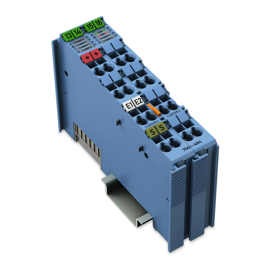
Device Description WAGO-I/O-SYSTEM 750 750-484 2 AI 4-20 mA HART Ex i View Figure 1: View Table 5: Legend for Figure “View” Pos. Description Details See Section Marking possibility with Mini- Status LEDs “Device Description” > “Display Elements” Data contacts “Device Description”... -
Page 17: Connectors
WAGO-I/O-SYSTEM 750 Device Description 750-484 2 AI 4-20 mA HART Ex i Connectors 3.2.1 Data Contacts/Internal Bus Communication between the fieldbus coupler/controller and the I/O modules as well as the system supply of the I/O modules is carried out via the internal bus. It is comprised of 6 data contacts, which are available as self-cleaning gold spring contacts. -
Page 18: Power Jumper Contacts/Field Supply
The blade contacts are sharp-edged. Handle the I/O module carefully to prevent injury. The I/O module 750-484 has 2 self-cleaning power jumper contacts that supply and transmit power for the field side. The contacts on the left side of the I/O module are designed as blade contacts and those on the right side as spring contacts. -
Page 19: Cage Clamp ® Connectors
WAGO-I/O-SYSTEM 750 Device Description 750-484 2 AI 4-20 mA HART Ex i ® 3.2.3 CAGE CLAMP Connectors ® Figure 4: CAGE CLAMP Connectors ® Table 7: Legend for Figure “CAGE CLAMP Connectors” Channel Designation Connector Function HART 1 + 1 (left) -
Page 20: Display Elements
Device Description WAGO-I/O-SYSTEM 750 750-484 2 AI 4-20 mA HART Ex i Display Elements Figure 5: Display Elements Table 8: Legend for Figure „Display Elements“ Channel 1 Description Function Error state HART 1 HART 1 Hardware and software Green/Off 1 × flashing Power-On... -
Page 21: Schematic Diagram
WAGO-I/O-SYSTEM 750 Device Description 750-484 2 AI 4-20 mA HART Ex i Schematic Diagram Figure 6: Schematic Diagram Manual V 1.2.0 HW-Version 04, SW-Version 03... -
Page 22: Technical Data
Device Description WAGO-I/O-SYSTEM 750 750-484 2 AI 4-20 mA HART Ex i Technical Data 3.6.1 Device Data Table 9: Technical Data - Device Width 24 mm High (from upper edge of DIN 35 rail) 64 mm Length 100 mm Weight approx. -
Page 23: Inputs
WAGO-I/O-SYSTEM 750 Device Description 750-484 2 AI 4-20 mA HART Ex i 3.6.4 Inputs Table 12: Technical Data - Inputs Number of inputs Signal current 4 mA ... 20 mA Input filter parameterizable Resolution of the A/D converter 12 Bit Conversion time (typ.) -
Page 24: Explosion Protection
Device Description WAGO-I/O-SYSTEM 750 750-484 2 AI 4-20 mA HART Ex i 3.6.5 Explosion Protection Table 13: Technical Data – Explosion Protection Voltage supply via power jumper = 27.3 V contacts ( LK1, LK2) = 1.6 W Interface circuit = 5 V... -
Page 25: Climatic Environmental Conditions
WAGO-I/O-SYSTEM 750 Device Description 750-484 2 AI 4-20 mA HART Ex i Table 15: Technical Data – Power Jumper Contacts Power jumper contacts Blade/spring contact, self-cleaning Table 16: Technical Data – Data Contacts Data contacts Slide contact, hard gold plated, self- cleaning 3.6.7... -
Page 26: Approvals
Location Korea Certification MSIP-REM-W43-AIM750 The following Ex approvals have been granted to 750-484 I/O modules: TÜV 12 ATEX 106032 X I M2 (M1) Ex d [ia Ma] I Mb II 3 (1) G Ex ec [ia Ga] IIC T4 Gc II 3 (1) D Ex tc [ia Da] IIIC T135°C Dc... - Page 27 WAGO-I/O-SYSTEM 750 Device Description 750-484 2 AI 4-20 mA HART Ex i The following ship approvals have been granted to 750-484 I/O modules: ABS (American Bureau of Shipping) Federal Maritime and Hydrographic Agency BV (Bureau Veritas) DNV (Det Norske Veritas)
-
Page 28: Standards And Guidelines
Device Description WAGO-I/O-SYSTEM 750 750-484 2 AI 4-20 mA HART Ex i Standards and Guidelines 750-484 I/O modules meet the following standards and guidelines: EU Directive 2014/34/EU Explosive atmosphere EN 60079-0 Devices – General requirements Explosive atmosphere IEC 60079-7 Equipment protection by increased safety "e"... - Page 29 WAGO-I/O-SYSTEM 750 Device Description 750-484 2 AI 4-20 mA HART Ex i Explosive atmospheres CAN/CSA-C22.2 No. 60079-11 Equipment Protection by Intrinsic Safety "i" Explosive atmospheres CAN/CSA-C22.2 No. 60079-15 Equipment Protection by Intrinsic Safety "n" UL Standard for Safety – UL 508 for Industrial Control Equipment American National Standard –...
-
Page 30: Process Image
Evaluation of Status Byte Some fieldbus systems can process status information of process value by means of a status byte. This status byte can be displayed via the commissioning tool WAGO-I/O- CHECK. However, processing via the fieldbus coupler/controller is optional, which means that accessing or parsing the status information depends on the fieldbus system. -
Page 31: Ai 4-20 Ma + 6-Byte Mailbox
The IEC application can be implemented in the connected programmable fieldbus controller (PFC) of the fieldbus node with the WAGO-I/O-PRO programming tool or, if a fieldbus coupler is connected, in the superimposed controller. -
Page 32: Table 19: Input Process Image
Process Image WAGO-I/O-SYSTEM 750 750-484 2 AI 4-20 mA HART Ex i Table 19: Input Process Image Input Process Image Offset Designation of Bytes Remark Status byte Internal Use used internally MBX_RES Mailbox response data Analog input data Channel 1... -
Page 33: Ai 4-20 Ma, 1 Hart Variable Per Channel
WAGO-I/O-SYSTEM 750 Process Image 750-484 2 AI 4-20 mA HART Ex i 2 AI 4-20 mA, 1 HART Variable per Channel With the PROFIBUS DP/V1 Fieldbus Coupler 750-333 or Fieldbus Controller 750-833, when one HART dynamic variable per channel is incorporated (optionally PV, SV, TV, QV), the PROFIBUS telegram has a size of 12 bytes. -
Page 34: Ai 4-20 Ma, 3 Hart Variables Per Channel
Process Image WAGO-I/O-SYSTEM 750 750-484 2 AI 4-20 mA HART Ex i Table 24: PROFIBUS Telegram, 2 HART Variables per Channel PROFIBUS Telegram (2 Variables per Channel) Offset Designation of Bytes Remark Analog input data Channel 1 HV0_0 1st HART variable Channel 1... -
Page 35: Ai 4-20 Ma, 4 Hart Variables Per Channel
WAGO-I/O-SYSTEM 750 Process Image 750-484 2 AI 4-20 mA HART Ex i Table 25: PROFIBUS Telegram, 3 HART Variables per Channel PROFIBUS Telegram (3 Variables per Channel) Offset Designation of Bytes Remark Analog input data Channel 1 HV0_0 1st HART variable Channel 1... -
Page 36: Table 26: Profibus Telegram, 4 Hart Variables Per Channel
Process Image WAGO-I/O-SYSTEM 750 750-484 2 AI 4-20 mA HART Ex i Table 26: PROFIBUS Telegram, 4 HART Variables per Channel PROFIBUS Telegram (4 Variables per Channel) Offset Designation of Bytes Remark Analog input data Channel 1 Primary variable Channel 1... -
Page 37: Ai 4-20 Ma + Acyclic Profibus Services
WAGO-I/O-SYSTEM 750 Process Image 750-484 2 AI 4-20 mA HART Ex i AI 4-20 mA + Acyclic PROFIBUS Services With the PROFIBUS DP/V1 Fieldbus Coupler 750-333 or Fieldbus Controller 750-833, only the two cyclic AI process values are mapped into the process image of the connected coupler in the "2AI + acyclic PROFIBUS services"... -
Page 38: Appendix: Information For Hart Library
“Device Specific Commands.” Additional information for downloading the library The library can be downloaded from the WAGO Internet site at www.wago.com → Support → Additional documentation and information on automation products → WAGO Software → WAGO-I/O-PRO / CODESYS → (right column, “Additional Information”:) Libraries →... -
Page 39: Mounting
Don't forget the bus end module! Always plug a bus end module (750-600) onto the end of the fieldbus node! You must always use a bus end module at all fieldbus nodes with WAGO-I/O- SYSTEM 750 fieldbus couplers/controllers to guarantee proper data transfer. -
Page 40: Inserting And Removing Devices
Mounting WAGO-I/O-SYSTEM 750 750-484 2 AI 4-20 mA HART Ex i Inserting and Removing Devices Perform work on devices only if they are de-energized! Working on energized devices can damage them. Therefore, turn off the power supply before working on the devices. -
Page 41: Removing The I/O Module
WAGO-I/O-SYSTEM 750 Mounting 750-484 2 AI 4-20 mA HART Ex i 6.2.2 Removing the I/O Module Remove the I/O module from the assembly by pulling the release tab. Figure 9: Removing the I/O Module (Example) Electrical connections for data or power jumper contacts are disconnected when removing the I/O module. -
Page 42: Connect Devices
Only one conductor may be connected to each CAGE CLAMP Do not connect more than one conductor at one single connection! If more than one conductor must be routed to one connection, these must be connected in an up-circuit wiring assembly, for example using WAGO feed- through terminals. ®... -
Page 43: Power Supply Concept
WAGO-I/O-SYSTEM 750 Connect Devices 750-484 2 AI 4-20 mA HART Ex i Power Supply Concept Ex i I/O modules shall only be supplied via Ex i 24VDC power supply module! Ex i I/O modules shall only be operated with an Ex i 24VDC power supply module. -
Page 44: Figure 11: Supply Principle Ex I
Connect Devices WAGO-I/O-SYSTEM 750 750-484 2 AI 4-20 mA HART Ex i Figure 11: Supply Principle Ex i Figure 12: Overvoltage Categories Table 30: Legend for Figure “Overvoltage Categories” Pos. Explanation Fieldbus coupler/controller Filter module Ex i supply module Ex i I/O Modules End module Both overvoltage categories and rated surge voltage acc. -
Page 45: Power Supply Concept In Marine Applications
WAGO-I/O-SYSTEM 750 Connect Devices 750-484 2 AI 4-20 mA HART Ex i 7.2.1 Power Supply Concept in Marine Applications The appropriate filter module is required when using Ex i I/O modules in marine applications! Power supply to the Ex i supply module shall be provided via the appropriate filter module when using Ex i I/O modules in marine applications! Modules approved to category EMC1 (marine applications): 750-626 or 750-626/020-000. -
Page 46: Figure 14: Power Supply Concept, Category Emc2 (Marine Applications)
Connect Devices WAGO-I/O-SYSTEM 750 750-484 2 AI 4-20 mA HART Ex i Figure 14: Power Supply Concept, Category EMC2 (Marine Applications) Table 32: Legend for Figure “Power Supply Concept, Category EMC2 (Marine Applications)” Pos. Explanation Fieldbus coupler/controller Filter module (750-626, 750-626/020-000, 750-624, 750-624/020-000) -
Page 47: Connection Example
WAGO-I/O-SYSTEM 750 Connect Devices 750-484 2 AI 4-20 mA HART Ex i Connection Example Figure 15: Connection Example With 2 Passive HART Sensors To fulfill Ex i regulations, only passive transducers, that means without their own voltage supply, like adjustable resistances, pressure, flow and level meters, may be connected to the input module. -
Page 48: Function Description
WAGO as a free download. With the simple parameterization of the HART I/O module via GSD (device master data) or WAGO-I/O-CHECK, 4 operating modes can be selected specially for using the HART I/O module in PROFIBUS systems, in which up to 4 HART dynamic variables (PV, SV, TV, QV) can be incorporated in the cyclic process image. -
Page 49: Operating Modes
2-channel analog input module for 4 mA … 20 mA signals with HART functionality. In this default operating mode the I/O module can be connected to all WAGO couplers and controllers listed in the table “Compatibility List”. In this case, HART communication is enabled by a 6-byte mailbox, which is incorporated with the analog values in the cyclic process image. -
Page 50: Setting The Operating Mode Parameters
9.1.1 Setting Up using WAGO-I/O-CHECK It is only necessary to set the parameters of the HART I/O module using WAGO- I/O-CHECK when the default operating mode (2AI + 6-byte mailbox) has been changed to the “PROFIBUS operating mode” (2 AI + acyclic PROFIBUS services) and is then to be changed back to the default mode. -
Page 51: Figure 16: Wago-I/O-Check Context Menu „Settings
WAGO-I/O-SYSTEM 750 Operating Modes 750-484 2 AI 4-20 mA HART Ex i Fieldbus Node must be without power! The Communication cable 750-920 shall not be connected or removed when the system is energized; i.e., there shall be no power to the coupler/controller! After installing WAGO-I/O-CHECK via the installation wizard, open it. -
Page 52: Figure 17: Wago-I/O-Check Dialog Window "Settings For 0750-0484
Figure 18: WAGO-I/O-CHECK Message for Successfully Parameterizing Additional Information about WAGO-I/O-CHECK You will find a detailed description of the functions and use of the commissioning tool in the 759-302 WAGO-I/O-CHECK manual on the Internet under: www.wago.com Manual V 1.2.0 HW-Version 04, SW-Version 03... -
Page 53: Setting Up Via Gsd
GSD files. Additional Information for Download the GSD Files The GSD files can be downloaded free of charge from the WAGO website at: www.wago.com → Support → Additional documentation and information on automation products →... -
Page 54: Figure 19: Gsd Configuration
Operating Modes WAGO-I/O-SYSTEM 750 750-484 2 AI 4-20 mA HART Ex i Figure 19: GSD Configuration To open the parameterization dialog to the selected module, click on the button with three points [...] in the “UsrPrm” (User Parameter) column. Depending on the selected operating mode, various set-up options, which are listed in the following tables, are provided in the dialog box which then opens. -
Page 55: Figure 20: Parameterization Dialog For Selecting 75X-484 2Ai/4-20 Ma/Se/Ex I
WAGO-I/O-SYSTEM 750 Operating Modes 750-484 2 AI 4-20 mA HART Ex i 75x-484 2AI/4-20 mA/SE /Ex i Figure 20: Parameterization Dialog for Selecting 75x-484 2AI/4-20 mA/SE/Ex i Manual V 1.2.0 HW-Version 04, SW-Version 03... -
Page 56: Table 35: General Parameter Data
Operating Modes WAGO-I/O-SYSTEM 750 750-484 2 AI 4-20 mA HART Ex i Parameters for all Operating Modes Table 35: General Parameter Data Parameter Value Description Terminal is - Plugged - I/O module is physically plugged in physically - Unplugged - I/O module is not physically plugged in Number of preamble bytes. -
Page 57: Fdt/Dtm Concept
FDT/DTM is an open concept, which encourages a uniform operating concept within an overall control program in which individual components from different manufacturers can work together. WAGO provides a simple and convenient FDT frame application in the form of the “759 370 WAGOframe FDT Frame Application” software. Manual... -
Page 58: Hart On Profibus
Operating Modes WAGO-I/O-SYSTEM 750 750-484 2 AI 4-20 mA HART Ex i Additional Information about WAGOframe Please read the “759 370 WAGOframe FDT Frame Application” manual for detailed information on the installation and use of the “759-370 WAGOframe” Software. You will find this on the Internet at: www.wago.com... -
Page 59: Figure 22: Operation Of Hart Devices Via Profibus
WAGO-I/O-SYSTEM 750 Operating Modes 750-484 2 AI 4-20 mA HART Ex i This solution includes the use of the PROFIBUS communications mechanisms without change to the PROFIBUS protocol and services, the PDUs or the state machines and functional characteristics. The HART client application is integrated within a PROFIBUS master and the HART master within a PROFIBUS slave, the latter serving as a multiplexer and handling the communication with the HART devices. -
Page 60: Description Of Operation
With PLC Library on all compatible 75x-xxx Couplers/Controllers With the default parameter settings “2AI + 6-byte mailbox”, the HART I/O module can be used with all WAGO 75x-xxx couplers/controllers of the WAGO- I/O-SYSTEM with HART functionality, which are listed in the table “Compatibility List”. -
Page 61: Communication With 75X-Xxx Via Plc Library
You can read a detailed description with a clear application example for the library “WagoLibHART_0x.lib” with WAGO-I/O-PRO CAA in the appropriate application note, which describes the HART application using this library. You will find this application note on the WAGO website at: www.wago.com Manual... -
Page 62: Commissioning On A 75X-Xxx Via Plc Library
PROFIBUS system, the operating mode must be re-parameterized for the default setting. To do this, open WAGO-I/O-CHECK, and set the operating mode to “2 AI + 6-byte mailbox“. For this purpose, proceed as described in the section “Operating Modes”... -
Page 63: With Hart Dynamic Variables On Profibus Dp/V1 750-333 And 750-833
Figure 24: WAGO-I/O-PRO Project with Incorporated Library “WagoLibHART_0x.lib” Additional Information about WAGO-I/O-PRO CAA You will find a detailed description of the functions and use of the WAGO-I/O- PRO CAA IEC 61131-3 programming tool in the 759-333 WAGO-I/O-PRO CAA manual on the Internet at: www.wago.com... - Page 64 Because of the process data capacity of the HART I/O module, please be sure to take into account the corresponding maximum number of modules that can be connected when using a WAGO PROFIBUS DP/V1 Coupler 750-333 or Controller 750-833. You can find this number in the table “Compatibility List”.
-
Page 65: Communication On The 750-333, -833 With Dynamic Variables
10.2.1 Communication on the 750-333, -833 with Dynamic Variables The use of the HART I/O module with a WAGO PROFIBUS DP/V1 Coupler 750-333 or Controller 750-833 is described briefly below. Figure 25: System Overview with a PROFIBUS Fieldbus Coupler/Controller The WAGO fieldbus node with PROFIBUS DP/V1 coupler/controller serves as a data gatherer/distributor for the superimposed controller. -
Page 66: Table 40: Software Required For The Commissioning On A 750-333, -833 With
Manager,…) A PROFIBUS Coupler 750-333 or Controller 750-833 is operated on a PROFIBUS master; e.g., on a 750-870 WAGO IPC, an S7 or another PROFIBUS master station. In this case, WAGO-I/O-PRO CAA (Item No.: 759-333), the “SIMATIC Manager” or other IEC development tools can be used for the configuration software. -
Page 67: Fdt/Dtm With The Profibus Dp/V1 750-333, 750-833
750-484 2 AI 4-20 mA HART Ex i “PROFIBUS-DP >Other FIELD DEVICES >I/O >WAGO I/O-SYSTEM 750”. Change the address to the station address of the WAGO PROFIBUS DP/V1 coupler/controller previously set on the DIP switch. Now expand the device catalog and using “Drag&Drop” add the remaining I/O modules that you have plugged into your fieldbus node on the coupler/controller. -
Page 68: Communication On 750-333, -833 Via Fdt/Dtm
Because of the process data capacity of the HART I/O module, please be sure to take into account the corresponding maximum number of modules that can be connected when using a WAGO PROFIBUS DP/V1 Coupler 750-333 or Controller 750-833. You can find this number in the list of the table “Compatibility List”. -
Page 69: Commissioning On A 750-333, -833 Via Fdt/Dtm
“Operating Modes“ > … > “Setting Up via GSD”. Alternatively you can also open WAGO-I/O-CHECK if available. In this case, proceed as described in the section “Operating Modes Parameters” > … > “Setting Up using WAGO-I/O-CHECK”. - Page 70 Description of Operation WAGO-I/O-SYSTEM 750 750-484 2 AI 4-20 mA HART Ex i Open WAGOframe in “Expert mode”. Next make sure that the “Device catalog” dialog window is shown on the right-hand side of the screen. This must be activated under Device catalog on the View menu.
-
Page 71: Figure 28: Dialog Window "Device List
WAGO-I/O-SYSTEM 750 Description of Operation 750-484 2 AI 4-20 mA HART Ex i Figure 28: Dialog Window “Device List” Select the device with the address 126 by clicking on it and click [Set DTM Tag/Address...]. Now, instead of the 126, enter the station address, which is physically set by the two rotary decade switches (decimal) on your PROFIBUS coupler/controller, for the “DP slave address”... -
Page 72: Figure 29: Dialog Window 750-333 Configuration, Register Device
Description of Operation WAGO-I/O-SYSTEM 750 750-484 2 AI 4-20 mA HART Ex i Figure 29: Dialog Window 750-333 Configuration, Register Device Information Select the register Module Configuration and identify for Slot(2) ... Slot(x) which module is physically plugged in to its fieldbus node. Pay attention to all I/O modules that deliver process data in the process image. -
Page 73: Figure 30: Dialog Window 750-333 Configuration, Register Module
WAGO-I/O-SYSTEM 750 Description of Operation 750-484 2 AI 4-20 mA HART Ex i Figure 30: Dialog Window 750-333 Configuration, Register Module Configuration Select the register Parameterization and open a dialog view in which you can make additional parameter changes. Confirm the changes made here by clicking [Apply]. -
Page 74: Figure 31: Dialog Window 750-333 Configuration, Register Parameterization
Description of Operation WAGO-I/O-SYSTEM 750 750-484 2 AI 4-20 mA HART Ex i Figure 31: Dialog Window 750-333 Configuration, Register Parameterization When configuration is completed, close the configuration dialog window. Use the mouse to select the communications DTM in the tree structure and right click on Offline Parameterization in the context menu. -
Page 75: Figure 32: Dialog Window Dtm Parameters
WAGO-I/O-SYSTEM 750 Description of Operation 750-484 2 AI 4-20 mA HART Ex i Figure 32: Dialog Window DTM Parameters Select the desired module from the left side of the tree structure; the displayed module number corresponds to the slot in the structure – module 01 is the bus coupler. -
Page 76: Figure 33: Dialog Window Detail: Setting For Channel 1
Description of Operation WAGO-I/O-SYSTEM 750 750-484 2 AI 4-20 mA HART Ex i Figure 33: Dialog Window Detail: Setting for Channel 1 Proceed in the same manner for all additional modules. When parameter settings are complete, confirm by clicking [OK]. -
Page 77: Figure 35: Dialog Window Device List, Update
WAGO-I/O-SYSTEM 750 Description of Operation 750-484 2 AI 4-20 mA HART Ex i Confirm the selection by clicking [OK]. Depending on the entry “<M01_Ch01>...HART DTM*” or “<M01_Ch01>...HART DTM*” will be added in the tree structure. If a HART device is connected to both channels, carry out these steps for the first channel and then again in a similar manner for the second channel. -
Page 78: Use In Hazardous Environments
WAGO-I/O-SYSTEM 750 750-484 2 AI 4-20 mA HART Ex i Use in Hazardous Environments The WAGO-I/O-SYSTEM 750 (electrical equipment) is designed for use in Zone 2 hazardous areas. The following sections include both the general identification of components (devices) and the installation regulations to be observed. The individual subsections of the “Installation Regulations”... -
Page 79: Marking Configuration Examples
WAGO-I/O-SYSTEM 750 Use in Hazardous Environments 750-484 2 AI 4-20 mA HART Ex i 11.1 Marking Configuration Examples 11.1.1 Marking for Europe According to ATEX and IECEx Figure 36: Marking Example According to ATEX and IECEx Figure 37: Text Detail – Marking Example According to ATEX and IECEx Manual V 1.2.0 HW-Version 04, SW-Version 03... -
Page 80: Table 42: Description Of Marking Example According To Atex And Iecex
Use in Hazardous Environments WAGO-I/O-SYSTEM 750 750-484 2 AI 4-20 mA HART Ex i Table 42: Description of Marking Example According to ATEX and IECEx Marking Description TUEV 07 ATEX 554086 X Approving authority resp. certificate numbers IECEx TUN 09.0001 X... -
Page 81: Figure 38: Marking Example For Approved Ex I I/O Module According To Atex And Iecex
WAGO-I/O-SYSTEM 750 Use in Hazardous Environments 750-484 2 AI 4-20 mA HART Ex i Figure 38: Marking Example for Approved Ex i I/O Module According to ATEX and IECEx Figure 39: Text Detail – Marking Example for Approved Ex i I/O Module According to ATEX... -
Page 82: Marking For America (Nec) And Canada (Cec)
Use in Hazardous Environments WAGO-I/O-SYSTEM 750 750-484 2 AI 4-20 mA HART Ex i Table 43: Description of Marking Example for Approved Ex i I/O Module According to ATEX and IECEx Marking Description TUEV 12 ATEX 106032 X Approving authority resp. certificate numbers... -
Page 83: Figure 40: Marking Example According To Nec
WAGO-I/O-SYSTEM 750 Use in Hazardous Environments 750-484 2 AI 4-20 mA HART Ex i Figure 40: Marking Example According to NEC Figure 41: Text Detail – Marking Example According to NEC 500 Table 44: Description of Marking Example According to NEC 500... -
Page 84: Table 45: Description Of Marking Example For Approved Ex I I/O Module
Use in Hazardous Environments WAGO-I/O-SYSTEM 750 750-484 2 AI 4-20 mA HART Ex i Figure 42: Text Detail – Marking Example for Approved Ex i I/O Module According to NEC 505 Table 45: Description of Marking Example for Approved Ex i I/O Module According to NEC 505... -
Page 85: Table 47: Description Of Marking Example For Approved Ex I I/O Modules
WAGO-I/O-SYSTEM 750 Use in Hazardous Environments 750-484 2 AI 4-20 mA HART Ex i Figure 44: Text Detail – Marking Example for Approved Ex i I/O Modules According to CEC 18 attachment J Table 47: Description of Marking Example for Approved Ex i I/O Modules According to CEC 18... -
Page 86: Installation Regulations
Use in Hazardous Environments WAGO-I/O-SYSTEM 750 750-484 2 AI 4-20 mA HART Ex i 11.2 Installation Regulations For the installation and operation of electrical equipment in hazardous areas, the valid national and international rules and regulations which are applicable at the installation location must be carefully followed. - Page 87 WAGO-I/O-SYSTEM 750 Use in Hazardous Environments 750-484 2 AI 4-20 mA HART Ex i Explosive atmosphere occurring simultaneously with assembly, installation or repair work must be ruled out. Among other things, these include the following activities • Insertion and removal of components •...
-
Page 88: Special Notes Regarding Ansi/Isa Ex
Use in Hazardous Environments WAGO-I/O-SYSTEM 750 750-484 2 AI 4-20 mA HART Ex i 11.2.2 Special Notes Regarding ANSI/ISA Ex For ANSI/ISA Ex acc. to UL File E198726, the following additional requirements apply: • Use in Class I, Division 2, Group A, B, C, D or non-hazardous areas only •... -
Page 89: Appendix
WAGO-I/O-SYSTEM 750 Appendix 750-484 2 AI 4-20 mA HART Ex i Appendix 12.1 Rated Surge Voltage Table 48: Rated Surge Voltage Nominal voltage of Line-to-neutral voltage, Rated surge voltage the power supply system derived from the nominal (mains) acc. to IEC 60038 3... -
Page 90: List Of Figures
List of Figures WAGO-I/O-SYSTEM 750 750-484 2 AI 4-20 mA HART Ex i List of Figures Figure 1: View ....................... 16 Figure 2: Data Contacts ..................17 Figure 3: Power Jumper Contacts ................. 18 ® Figure 4: CAGE CLAMP Connectors..............19 Figure 5: Display Elements ................... - Page 91 WAGO-I/O-SYSTEM 750 List of Figures 750-484 2 AI 4-20 mA HART Ex i Figure 42: Text Detail – Marking Example for Approved Ex i I/O Module According to NEC 505................. 84 Figure 43: Text Detail – Marking Example for Approved Ex i I/O Module According to NEC 506.................
-
Page 92: List Of Tables
List of Tables WAGO-I/O-SYSTEM 750 750-484 2 AI 4-20 mA HART Ex i List of Tables Table 1: Number Notation ..................8 Table 2: Font Conventions ..................8 Table 3: Types of Application ................14 Table 4: Compatibility List ................... 15 Table 5: Legend for Figure “View”... - Page 93 WAGO-I/O-SYSTEM 750 List of Tables 750-484 2 AI 4-20 mA HART Ex i Table 43: Description of Marking Example for Approved Ex i I/O Module According to ATEX and IECEx ..............82 Table 44: Description of Marking Example According to NEC 500 ....83 Table 45: Description of Marking Example for Approved Ex i I/O Module According to NEC 505.................
- Page 94 WAGO Kontakttechnik GmbH & Co. KG Postfach 2880 • D-32385 Minden Hansastraße 27 • D-32423 Minden Phone: 05 71/8 87 – 0 Fax: 05 71/8 87 – 1 69 E-Mail: info@wago.com Internet: http://www.wago.com...
Need help?
Do you have a question about the 750-484 and is the answer not in the manual?
Questions and answers