Sign In
Upload
Manuals
Brands
Suzuki Manuals
Automobile
Liana RH418
Suzuki Liana RH418 Manuals
Manuals and User Guides for Suzuki Liana RH418. We have
1
Suzuki Liana RH418 manual available for free PDF download: Supplementary Service Manual
Suzuki Liana RH418 Supplementary Service Manual (372 pages)
Brand:
Suzuki
| Category:
Automobile
| Size: 17.21 MB
Table of Contents
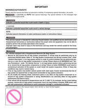
Warning/Caution/Note
1
Table of Contents
3
General Information
5
Transmission Identification Number
6
Automatic Transaxle Fluid Cooler Hose Inspection
7
Automatic Transaxle Fluid Inspection
7
Automatic Transaxle Fluid Replacement
7
Maintenance and Lubrication
7
Transfer Oil (4WD A/T) and Rear Differential Oil (4WD) Inspection
8
Engine
9
Precautions for Engine
13
Precautions on Engine Service
14
Precautions in Diagnosing Trouble
14
Engine General Information and Diagnosis
14
On-Board Diagnostic System Description
15
Statement on Cleanliness and Care
15
Engine Diagnosis General Description
15
Data Link Connector (DLC)
16
Driving Cycle
16
Engine and Emission Control System Description
16
Pending DTC
16
Air Intake System Description
17
Electronic Control System Description
17
Engine and Emission Control System Flow Diagram
18
ECM Input / Output Circuit Diagram
19
Terminal Arrangement of ECM Coupler (Viewed from Harness Side)
20
Connector: G04
21
Connector: C41
21
Connector: G03
21
Engine and Emission Control Input / Output Table
22
Engine and Emission Control System Diagram
23
Electronic Control System Components Location
25
Diagnostic Information and Procedures (Engine)
26
Engine and Emission Control System Check
26
Customer Complaint Analysis
27
DTC Check
28
Malfunction Indicator Lamp (MIL) Check
28
DTC Clearance
29
DTC Table
30
Fail-Safe Table
31
Scan Tool Data
32
Scan Tool Data Definitions
34
Engine Basic Inspection
36
Visual Inspection (Engine)
36
Engine Symptom Diagnosis
40
Malfunction Indicator Lamp Does Not Come on at Ignition Switch on (but Engine at Stop)
49
Malfunction Indicator Lamp Remains on after Engine Starts
51
MIL Flashes at Ignition Switch on
52
MIL Does Not Flash or Just Remains on Even with Grounding Diagnosis Switch Terminal
53
MIL Does Not Light at Ignition Switch on and Engine Does Not Start through It Is Cranked up
54
DTC P0011 (No. 32) / P0012 (No. 32): Camshaft Position-Timing Over-Advanced or System
57
Performance / Timing Over-Retarded
57
DTC P0105 (No. 11): Manifold Absolute Pressure (MAP) Circuit Malfunction
59
DTC P0110 (No. 18): Intake Air Temp. (IAT) Circuit Malfunction
61
DTC P0115 (No. 19): Engine Coolant Temp. (ECT) Circuit Malfunction
63
DTC P0120 (No. 13): Throttle Position Circuit Malfunction
65
DTC P0130 (No. 14): Heated Oxygen Sensor (HO2S) Circuit Malfunction (Sensor-1)
67
DTC P0135 (No. 14): Heated Oxygen Sensor (HO2S) Heater Circuit Malfunction (Sensor-1)
69
DTC P0325 (No. 17): Knock Sensor Circuit Malfunction
71
DTC P0335 (No. 23): Crankshaft Position (CKP) Sensor Circuit Malfunction
73
DTC P0340 (No. 15): Camshaft Position (CMP) Sensor Circuit Malfunction
76
DTC P0500 (No. 16): Vehicle Speed Sensor (VSS) Malfunction
79
DTC P0601: Internal Control Module Memory Check Sum Error
83
DTC P1450 (No.29): Barometric Pressure Sensor Circuit Malfunction
83
DTC P1915 (No. 33): Oil Control Valve Circuit
84
Voltage Check
86
Reference Waveform No.4 - Heated Oxygen Sensor-1 Heater Signal at Engine Idling
91
Reference Waveform No.2 - Oil Control Valve Signal at Vehicle Driving
91
Reference Waveform No.1 - Oil Control Valve Signal at Ignition Switch on
91
Reference Waveform No.3 - Heated Oxygen Sensor-1 Signal at Engine Idling
91
Reference Waveform No.5 - IAC Valve Signal
92
Reference Waveform No.6 - Ignition Coil No.2 and No.3 Signal at Engine Idling
92
Reference Waveform No.7 - Ignition Coil No.1 and No.4 Signal at Engine Idling
92
Reference Waveform No.8 - Fuel Injector Signal at Engine Idling
92
Reference Waveform No.10 - No.3 Fuel Injector Signal at Engine Idling
93
Reference Waveform No.11 - No.2 Fuel Injector Signal at Engine Idling
93
Reference Waveform No.12 - No.1 Fuel Injector Signal at Engine Idling
93
Reference Waveform No.9 - No.4 Fuel Injector Signal at Engine Idling
93
Reference Waveform No.16 - Manifold Absolute Pressure Sensor Signal at Ignition Switch Turned on
94
Reference Waveform No.13 - Knock Sensor Signal at Engine Speed 4000 R/Min
94
Reference Waveform No.15 - CMP Sensor Signal at Engine Idling
94
Reference Waveform No.14 - Knock Sensor Signal at Engine Speed 4000 R/Min
94
Reference Waveform No.17 - Manifold Absolute Pressure Sensor Signal at Engine Racing
95
Reference Waveform No.18 - VSS Signal at 30 Km/H (19 Mil/H)
95
Reference Waveform No.19 - Tachometer (Ignition Pulse) Signal at Engine Idling
95
Reference Waveform No.20 - Tachometer (Ignition Pulse) Signal at Engine Idling
95
Reference Waveform No.21 - Engine Coolant Temperature Signal at Engine Idling
96
Reference Waveform No.22 - EVAP Canister Purge Valve Signal
96
Reference Waveform No.23 - Ignition Coil Signal and Fuel Injector Signal at Engine Cranking
96
Reference Waveform No.24 - Fuel Injector Signal at Engine Cranking
96
Resistance Check
97
Fuel Injector Circuit Check
98
Fuel Pump and Its Circuit Check
99
Fuel Pressure Check
101
Idle Air Control System Check
102
Idle Air Control Circuit Check
105
Throttle Valve Opening Signal Inspection
106
Electric Load Signal Circuit Check
111
Radiator Fan Control System Check
112
Radiator Fan Control Circuit Check
114
Power Steering Pressure (PSP) Switch Signal Circuit Check
117
Generator Control Signal Circuit Check
119
Idle Speed / Idle Air Control (IAC) Duty Inspection
120
Repair Instructions
120
Engine Idle Speed and IAC Duty
121
Special Tools
122
Aux. Emission Control Devices
123
Vacuum Hose Inspection
123
Vacuum Passage Inspection
123
Engine Electrical Devices
124
Idle Air Control (IAC) Valve Inspection
124
Idle Air Control (IAC) Valve Removal and Installation
124
Heated Oxygen Sensor (HO2S) Removal and Installation
125
Oil Control Valve Inspection
125
Oil Control Valve Removal and Installation
125
Camshaft Position (CMP) Sensor Removal and Installation
126
Oxygen Sensor Heater Inspection
126
Engine Mechanical
127
Engine Construction Description
127
Variable Valve Timing (VVT) System Description
128
Cam Timing Sprocket
129
Oil Control Valve
129
Timing Advancing
129
Timing Holding
129
Targeted Timing Varying Operation
130
Timing Retarding
130
Compression Check
131
Diagnostic Information and Procedures
131
Engine Vacuum Check
132
Valve Clearance Specification
133
Valve Lash (Clearance) Inspection
133
Replacement of Shim
134
Accelerator Cable Adjustment
136
Air Cleaner Element Inspection and Cleaning
136
Air Cleaner Element Removal and Installation
136
Throttle Body Components
137
Throttle Body On-Vehicle Inspection
137
Throttle Body Removal and Installation
137
Throttle Body Cleaning
138
Throttle Body Disassembly and Assembly
138
Throttle Body and Intake Manifold Components
139
Throttle Body and Intake Manifold Removal and Installation
140
Cylinder Head Cover Removal and Installation
141
Engine Mountings Components
143
Engine Assembly Removal and Installation
144
Timing Chain Cover Components
147
Timing Chain Cover Removal and Installation
148
Timing Chain Cover Cleaning and Inspection
150
Timing Chain and Chain Tensioner Components
151
Timing Chain and Chain Tensioner Removal and Installation
152
Timing Chain and Chain Tensioner Inspection
155
Camshaft, Tappet and Shim Components
156
Camshaft, Tappet and Shim Removal and Installation
156
Camshaft, Tappet and Shim Inspection
159
Wear of Tappet and Shim
161
Valves and Cylinder Head Components
162
Valves and Cylinder Head Removal and Installation
163
Valves and Cylinder Head Disassembly and Assembly
165
Valves and Valve Guides Inspection
167
Cylinder Head Inspection
169
Valve Spring Inspection
170
Pistons, Piston Rings and Connecting Rods Components
171
Pistons, Piston Rings and Connecting Rods Removal and Installation
172
Pistons, Piston Rings, Connecting Rods and Cylinders Disassembly and Assembly
173
Cylinders, Pistons and Piston Rings Inspection
174
Piston Pins and Connecting Rods Inspection
176
Crank Pin and Connecting Rod Bearings Inspection
177
Connecting Rod Bearing Visual Inspection
178
Connecting Rod Bearing General Information
178
Connecting Rod Bearing Clearance
178
Selection of Connecting Rod Bearings
179
Main Bearings, Crankshaft and Cylinder Block Components
181
Main Bearings, Crankshaft and Cylinder Block Removal and Installation
182
Crankshaft Inspection
185
Main Bearings Inspection
186
Crankshaft Bearing Cap Bore
188
Crankshaft Journal Diameter
188
Selection of Main Bearings
188
New Standard Size Crankshaft Main Bearing Specification
189
Standard Size of Crankshaft Main Bearing Thickness
189
Undersize of Crankshaft Main Bearing Thickness
189
Sensor Plate Inspection
190
New Standard Undersize Crankshaft Main Bearing Specification
190
Bearing Cap Bolt
190
Cylinder Block Inspection
191
Flywheel Inspection
191
Rear Oil Seal Inspection
191
Tightening Torque Specifications
192
Special Tools and Equipment
193
Engine Lubrication System
195
Oil Pan and Oil Pump Strainer Components
196
Oil Pan and Oil Pump Strainer Removal and Installation
196
Oil Pump Components
198
Oil Pump Disassembly and Assembly
198
Tightening Torque Specifications (Engine Lubrication System)
200
Special Tools and Equipment (Engine Lubrication System)
200
Fuel Pipe Removal and Installation
201
Fuel System
201
Fuel Injector Removal and Installation
202
Fuel Injector Inspection
203
Fuel Pressure Regulator Removal and Installation
204
Fuel Tank Removal and Installation
205
Tightening Torque Specifications (Fuel System)
208
Table of Contents
209
Driveline / Axle
209
Diagnostic Information and Procedures
210
Front Drive Shaft Components
210
3A-1 Drive Shaft / Axle
210
Repair Instructions
210
Front Drive Shaft Assembly Removal and Installation
211
Front Drive Shaft Disassembly and Assembly
213
Drive Shaft Damper Installing Position
216
Drive Shaft Boot Fixing Position
217
Drive Shaft Joint Cage Installing Pipe Diameter
218
Tightening Torque Specifications (Drive Shaft/Axle)
221
Special Tools and Equipment (Drive Shaft/Axle)
221
Recommended Service Material
221
Transmission / Transaxle
223
Precautions on Transmission / Transaxle
226
Automatic Transmission/Transaxle
227
Precautions
227
Precautions in Diagnosing Trouble
227
Reassembly
227
Automatic Transmission/Transaxle Description
228
General Description
228
Automatic Transmission/Transaxle Specifications
230
Clutch / Brake / Planetary Gear Function of Automatic Transaxle
230
Table of Component Operation
231
A/T Diagnosis General Description
232
On-Board Diagnostic System Description (A/T)
232
Transmission Control Module (TCM) Wiring Diagram
233
Schematic and Routing Diagram
233
Operation of Shift Solenoid Valves and TCC Solenoid Valve
234
Automatic Gear Shift Diagram
235
Electronic Shift Control System Components Location
236
Diagnostic Information and Procedures (A/T)
237
A/T System Check
237
Visual Inspection
237
Customer Complaint Analysis (A/T)
238
Visual Inspection - A/T
240
“O/D OFF” Lamp Check
240
DTC Table
240
Displaying DTC on Odometer
242
DTC Check
242
DTC Clearance Using SUZUKI Scan Tool
243
DTC Clearance Using Monitor Connector
243
Fail Safe Table (A/T)
244
Scan Tool Data (A/T)
245
A/T Basic Check
247
Road Test
248
Manual Road Test
249
Stall Test
250
Time Lag Test
251
Line Pressure Test
252
Engine Brake Test
253
"P" Range Test
253
A/T Symptom Diagnosis
254
Electrical Repair
254
On-Vehicle Repair
256
Off-Vehicle Repair
258
No Gear Shift to O/D
259
No Lock-Up Occurs
260
DTC P0705 (No.34): Transmission Range Sensor Circuit Malfunction (PRNDL Input)
261
DTC P0710 (No.36 / No.38): Transmission Fluid Temperature Sensor Circuit Malfunction
263
DTC P0715 (No.37): Input / Turbine Speed Sensor Circuit Malfunction
265
DTC P0720 (No.31): Output Shaft Speed Sensor Circuit Malfunction
267
DTC P0725 (No.35): Engine Speed Input Circuit Malfunction
269
DTC P0743 (No.25 / No.26) Torque Converter Clutch Circuit Electrical
271
DTC P0748 (No.41 / No.42): Pressure Control Solenoid-A Electrical
273
DTC P0753 / P0758 (No.21 / No.22 / No.23 / No.24): Shift Solenoid-A (No.1) Electrical / Shift Solenoid-B (No.2) Electrical
275
DTC P1700 (No.32 / No.33): Throttle Position Signal Input Malfunction
277
DTC P1702 (No.52): Internal Malfunction of TCM
278
DTC P1705 (No.51): Engine Coolant Temperature Signal Circuit Malfunction
279
DTC P1730 (No.64) Engine Torque Signal Circuit Malfunction
281
DTC P1895 (No.27): Torque Control Signal Malfunction
282
Inspection of TCM and Its Circuits
284
TCM Power and Ground Circuit Check
287
“O/D OFF” Lamp Circuit Check
288
A/T Fluid Level Check
291
A/T Fluid Change
291
Repair Instructions
291
Select Cable Removal and Installation
292
Selector Lever Components
292
Selector Lever Inspection
292
Select Cable Components
293
Selector Cable Adjustment
293
Transmission Range Sensor (Shift Switch) Inspection and Adjustment
294
Output Shaft Speed Sensor Removal and Installation
295
Input Shaft Speed Sensor Removal and Installation
296
Input Shaft Speed Sensor Inspection
296
Transmission Fluid Temperature Sensor Installation
296
“O/D OFF” Switch Inspection
298
Solenoid Valves (Shift Solenoid Valves, TCC Solenoid Valve and Pressure Control Solenoid Valve) Removal and Installation
298
Solenoid Valves (Shift Solenoid Valves and TCC Solenoid Valve) Inspection
300
Pressure Control Solenoid Valve Inspection
301
Transmission Control Module (TCM) Removal and Installation
302
Differential Side Oil Seal Replacement
303
A/T Fluid Cooler Hoses Replacement
303
Automatic Transaxle Unit Components
304
Automatic Transaxle Unit Dismounting and Remounting
305
Automatic Transaxle Assembly Components
307
Automatic Transaxle Unit Disassembly
308
Oil Pump Components View
315
Oil Pump Disassembly and Reassembly
316
Oil Pump Inspection
317
Forward Clutch Components
318
Forward Clutch Preliminary Check
318
Forward Clutch Disassembly and Reassembly
319
Forward Clutch Inspection
321
Overdrive Clutch and Coast Clutch Preliminary Check
322
Overdrive Clutch and Coast Clutch Disassembly and Reassembly
323
Overdrive Clutch and Coast Clutch Inspection 5A-100
326
Planetary Gear Components
327
Planetary Gear Operation Check
328
Planetary Gear Disassembly and Reassembly
328
Rear Planetary Ring Gear Assembly
331
Planetary Gear Inspection
332
Reverse Clutch Components View
332
Reverse Clutch Preliminary Inspection
333
Reverse Clutch Disassembly and Reassembly
334
Reverse Clutch Inspection
336
Counter Drive Gear Components
337
Counter Drive Gear Disassembly and Reassembly
337
Counter Driven Gear Components
339
Counter Driven Gear Disassembly and Reassembly
340
Valve Body Assembly Components
342
Valve Body Assembly Disassembly and Reassembly
343
Differential Components View
344
Differential Removal and Installation
344
Available Differential Side Bearing Shim Thickness
345
Differential Inspection
346
Transaxle Housing Removal and Installation
346
Transaxle Housing Inspection
348
Transaxle Case Removal and Installation
348
Automatic Transaxle Unit Assembly
348
Sun Gear Thrust Roller Bearing Dimension
352
Istance between Forward Clutch Drum and Mating Surface of Transaxle Case
352
Distance between Input Shaft End and Mating Surface of Transaxle Case
354
Distance between Torque Converter and Mating Surface of Transaxle Housing
357
Tightening Torque Specifications (A/T)
358
Special Tools and Equipment (A/T)
359
Recommended Service Material
359
Body, Cab and Accessories
363
Instrumentation / Driver Info. / Horn
367
Combination Meter Circuit Diagram
367
Glass / Windows / Mirrors
369
Power Window Main Switch Inspection
369
Precautions
226
Advertisement
Advertisement
Related Products
Suzuki Liana RH413
Suzuki Liana RH416
Suzuki Reno 2008 Reno
Suzuki WagonR+ RB310
Suzuki Wagon R RB310
Suzuki Wagon R RB413
Suzuki RA410
Suzuki RF 410
Suzuki WagonR+ RB4130
Suzuki WagonR+ RB413
Suzuki Categories
Motorcycle
Automobile
Motorcycle Accessories
Offroad Vehicle
Musical Instrument
More Suzuki Manuals
Login
Sign In
OR
Sign in with Facebook
Sign in with Google
Upload manual
Upload from disk
Upload from URL