Sign In
Upload
Manuals
Brands
Rigol Manuals
Test Equipment
MSO5000 Series
Rigol MSO5000 Series Manuals
Manuals and User Guides for Rigol MSO5000 Series. We have
5
Rigol MSO5000 Series manuals available for free PDF download: User Manual, Quick Manual, Installation Manual
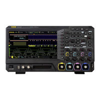
Rigol MSO5000 Series User Manual (372 pages)
Digital Oscilloscope
Brand:
Rigol
| Category:
Test Equipment
| Size: 18 MB
Table of Contents
Guaranty and Declaration
3
Safety Requirement
4
Safety Notices and Symbols
6
Measurement Category
7
Ventilation Requirement
7
Working Environment
8
Care and Cleaning
9
Environmental Considerations
10
MSO5000 Series Overview
11
Document Overview
12
Table of Contents
16
Chapter 1 Quick Start
25
General Inspection
26
Appearance and Dimensions
27
To Prepare for Use
28
To Adjust the Supporting Legs
28
To Connect to AC Power
28
Turn-On Checkout
29
To Connect the Probe
29
Function Inspection
32
Probe Compensation
33
Front Panel Overview
34
Rear Panel Overview
35
Front Panel Function Overview
37
Vertical
37
Horizontal
38
Trigger
39
Function Menu
39
Navigation Control Key
40
Quick Key (Shortcut Key)
40
Function/Arbitrary Waveform Generator Setting
41
Clear
41
Auto
41
Run/Stop
41
Single
41
Touch Lock Key
42
Default
42
Multifunction Knob
42
User Interface
43
Touch Screen Controls
47
Tap
47
Pinch & Stretch
47
Drag
48
Rectangle Drawing
48
Parameter Setting Method
50
To Use the Kensington Security Lock
51
To Use the Built-In Help System
52
To View the Option Information and the Option Installation
53
Chapter 2 To Set the Vertical System
55
To Enable or Disable the Analog Channel
56
To Adjust the Vertical Scale
57
Vertical Expansion
58
To Adjust the Vertical Offset
58
Channel Coupling
59
Bandwidth Limit
59
Probe Ratio
60
Input Impedance
61
Waveform Invert
61
Amplitude Unit
62
Channel Delay
62
Offset Cal
63
Channel Label
64
Chapter 3 To Set the Horizontal System
67
To Adjust the Horizontal Time Base
68
To Adjust the Horizontal Position
69
Delayed Sweep
70
Chapter 4 To Set the Sample System
73
Timebase Mode
74
YT Mode
74
XY Mode
74
ROLL Mode
76
Acquisition Mode
77
Normal
77
Average
77
Peak
78
High Resolution
79
Sampling Mode
79
Sample Rate
79
LA Sample Rate
81
Memory Depth
81
LA Memory Depth
82
Anti-Aliasing
83
Horizontal Expansion
83
Chapter 5 To Trigger the Oscilloscope
85
Trigger Source
86
Trigger Level/Threshold Level
87
Trigger Mode
88
Trigger Coupling
89
Trigger Holdoff
90
Noise Rejection
91
Trigger Type
92
Edge Trigger
93
Pulse Trigger
94
Slope Trigger
96
Video Trigger
99
Pattern Trigger
101
Duration Trigger
103
Timeout Trigger
106
Runt Trigger
107
Window Trigger
109
Delay Trigger
111
Setup/Hold Trigger
113
Nth Edge Trigger
116
RS232 Trigger (Option)
117
I2C Trigger (Option)
120
SPI Trigger (Option)
122
CAN Trigger (Option)
124
Flexray Trigger (Option)
127
LIN Trigger (Option)
129
I2S Trigger (Option)
131
MIL-STD-1553 Trigger (Option)
134
Zone Trigger
137
Trigger Output Connector
138
Chapter 6 Operations and Measurements
141
Math Operation
142
Addition
142
Subtraction
143
Multiplication
144
Division
145
Fft
146
AND" Operation
150
OR" Operation
151
XOR" Operation
152
NOT" Operation
153
Intg
155
Diff
156
Sqrt
157
Lg (Base 10 Exponential)
158
Exp
159
Abs
160
Low Pass
161
High Pass
162
Band Pass
163
Band Stop
164
Ax+B
165
Math Operation Label
166
Auto Measurement
167
Quick Measurement after AUTO
167
Measurement Parameter
170
Measurement Settings
176
Remove the Measurement Result
179
Statistical Function
179
All Measurement
180
Cursor Measurement
180
Manual Mode
182
Track Mode
186
XY Mode
188
Measure Mode
190
Chapter 7 Digital Voltmeter (DVM) and Frequency Counter
191
Digital Voltmeter (DVM)
192
To Enable or Disable DVM Measurement
192
To Select the Measurement Source
192
To Select Measurement Mode
193
To Set the Limits
193
Frequency Counter
194
To Enable or Disable the Frequency Counter
194
To Select the Measurement Source
194
To Select the Measurement Item
194
To Set Resolution
195
To Clear Count
195
To Enable or Disable the Statistical Function
195
Chapter 8 Power Analysis (Option)
197
Power Quality
198
Ripple
200
Chapter 9 Histogram Analysis
203
To Enable or Disable the Histogram Function
204
To Select the Histogram Type
204
To Select the Histogram Source
205
To Set the Histogram Height
205
To Set the Histogram Range
205
To Enable or Disable the Statistical Function
205
To Reset
206
Chapter 10 Digital Channel
207
To Select the Digital Channel
208
To Enable/Disable the Digital Channel
208
To Set the Threshold and Calibrate Probe
209
Auto Arrangement Setting
210
To Set the Waveform Display Size
210
To Set the Label
210
Group Setting
211
Waveform Color of the Digital Channel
212
Chapter 11 Protocol Decoding
213
Parallel Decoding
214
RS232 Decoding (Option)
219
I2C Decoding (Option)
226
SPI Decoding (Option)
230
LIN Decoding (Option)
235
CAN Decoding (Option)
240
Flexray Decoding (Option)
245
I2S Decoding (Option)
249
1553B Decoding (Option)
253
Chapter 12 Reference Waveform
257
To Enable Ref Function
258
To Select the Reference Channel
258
To Select the Ref Source
258
To Adjust the Ref Waveform Display
258
To Save to Internal Memory
259
To Clear the Display of the Reference Waveform
259
To View Details of the Reference Waveform
259
To Reset the Reference Waveform
260
Color Setting
260
Label Setting
260
To Export to Internal or External Memory
261
To Import from Internal or External Memory
261
Chapter 13 Pass/Fail Test
263
To Enable or Disable the Pass/Fail Test Function
264
To Start or Stop the Pass/Fail Test Operation
264
To Select the Source
264
To Create a Mask
265
To Save the Mask
265
To Load a Mask
265
To Set the Output Form of the Test Results
266
To Enable or Disable the Display of the Statistics of the Test Results
267
Statistics Reset
267
Chapter 14 Waveform Recording & Playing
269
Common Settings
270
Record Options
271
Play Options
272
Chapter 15 Search and Navigation Function
275
Search Function
276
Navigation Function
278
Chapter 16 Display Control
281
To Select the Display Type
282
To Set the Persistence Time
282
To Set the Waveform Intensity
283
To Set the Screen Grid
283
To Set the Grid Brightness
283
Scale
284
Color Grade
284
Waveform Freeze
284
Chapter 17 Function/Arbitrary Waveform Generator (Option)
285
To Output Basic Waveforms
286
To Output Sine
286
To Output Square
287
To Output Ramp
288
To Output Pulse
288
To Output DC
289
To Output Noise
289
Sinc
290
Exp.rise
290
Exp.fall
291
Ecg
291
Gauss
292
Lorentz
292
Haversine
293
To Output the Arbitrary Waveform
293
To Load the Channel and Waveform
293
To Create the Waveform
294
To Edit Waveforms
296
Modulation
297
Fsk
300
Sweep
300
Burst
303
Chapter 18 Store and Load
305
Storage System
306
Storage Type
306
Load Type
308
Internal Storage and Load
308
External Storage and Load
310
Disk Management
310
To Select a File Type
311
To Create a Folder
311
To Delete a File or Folder
315
To Copy and Paste a File or Folder
316
To Rename a File or Folder
316
To Clear the Internal Memory Safely
317
Factory Settings
317
Chapter 19 Bode Plot
329
To Enable the Bode Function
330
To Run or Stop the Operation
330
Parameter Setting
331
Source
331
Amp/Freq Set
331
Sweep Type
332
Out
333
Impedance
333
Cursor
333
Display Type
333
Wave Form
333
Chart
334
Display
335
Save
335
File Type
335
File Name
335
Newfolder
335
Window
335
Connection Diagram
335
Chapter 20 System Utility Function Setting
337
Remote Interface Configuration
338
LAN Configuration
338
To Set Mdns
341
To Set Host Name
341
To Set the GPIB Address
341
To Set HDMI
341
USB Connection
342
System-Related
343
Beeper
343
Language
343
System Information
343
Power on
343
Aux Output
344
Help
344
Self-Calibration
345
Auto Config
345
Print Setting
346
Email
347
Key Locker
348
Quick Operation
349
Self-Check
353
System Time
354
Chapter 21 Remote Control
357
Remote Control Via USB
358
Remote Control Via LAN
362
Remote Control Via GPIB
363
Chapter 22 Troubleshooting
365
Appendix A: Accessories and Options
367
Chapter 23 Appendix
367
Appendix B: Warranty
369
Index
371
Advertisement
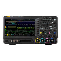
Rigol MSO5000 Series User Manual (358 pages)
Digital Oscilloscope
Brand:
Rigol
| Category:
Test Equipment
| Size: 9.33 MB
Table of Contents
Guaranty and Declaration
3
Safety Requirement
4
Safety Notices and Symbols
6
Measurement Category
7
Ventilation Requirement
7
Working Environment
8
Care and Cleaning
9
Environmental Considerations
10
MSO5000 Series Overview
11
Document Overview
12
Table of Contents
16
Chapter 1 Quick Start
23
General Inspection
24
Appearance and Dimensions
25
To Prepare for Use
26
To Adjust the Supporting Legs
26
To Connect to AC Power
26
Turn-On Checkout
27
To Connect the Probe
27
Function Inspection
30
Probe Compensation
31
Front Panel Overview
32
Rear Panel Overview
33
Front Panel Function Overview
35
Vertical
35
Horizontal
36
Trigger
37
Function Menu
37
Navigation Control Key
38
Quick Key (Shortcut Key)
38
Function/Arbitrary Waveform Generator Setting
39
Clear
39
Auto
39
Run/Stop
39
Single
39
Touch Lock Key
40
Default
40
Multifunction Knob
40
User Interface
41
Touch Screen Controls
45
Tap
45
Pinch & Stretch
45
Drag
46
Rectangle Drawing
46
Parameter Setting Method
48
To Use the Kensington Security Lock
49
To Use the Built-In Help System
50
To View the Option Information and the Option Installation
51
Chapter 2 To Set the Vertical System
53
To Enable or Disable the Analog Channel
54
To Adjust the Vertical Scale
55
Vertical Expansion
56
To Adjust the Vertical Offset
56
Channel Coupling
57
Bandwidth Limit
57
Probe Ratio
58
Input Impedance
59
Waveform Invert
59
Amplitude Unit
60
Channel Delay
60
Offset Cal
61
Channel Label
62
Chapter 3 To Set the Horizontal System
65
To Adjust the Horizontal Time Base
66
To Adjust the Horizontal Position
67
Delayed Sweep
68
Chapter 4 To Set the Sample System
71
Timebase Mode
72
YT Mode
72
XY Mode
72
ROLL Mode
74
Acquisition Mode
75
Normal
75
Average
75
Peak
76
High Resolution
77
Sampling Mode
77
Sample Rate
77
LA Sample Rate
79
Memory Depth
79
LA Memory Depth
80
Anti-Aliasing
81
Horizontal Expansion
81
Chapter 5 To Trigger the Oscilloscope
83
Trigger Source
84
Trigger Level/Threshold Level
85
Trigger Mode
86
Trigger Coupling
87
Trigger Holdoff
88
Noise Rejection
89
Trigger Type
90
Edge Trigger
91
Pulse Trigger
92
Slope Trigger
94
Video Trigger
97
Pattern Trigger
99
Duration Trigger
101
Timeout Trigger
103
Runt Trigger
105
Window Trigger
107
Delay Trigger
109
Setup/Hold Trigger
111
Nth Edge Trigger
113
RS232 Trigger (Option)
114
I2C Trigger (Option)
117
SPI Trigger (Option)
119
CAN Trigger (Option)
121
Flexray Trigger (Option)
124
LIN Trigger (Option)
126
I2S Trigger (Option)
128
MIL-STD-1553 Trigger (Option)
131
Zone Trigger
133
Trigger Output Connector
135
Chapter 6 Operations and Measurements
137
Math Operation
138
Addition
138
Subtraction
139
Multiplication
140
Division
141
Fft
142
AND" Operation
146
OR" Operation
147
XOR" Operation
148
NOT" Operation
150
Intg
151
Diff
152
Sqrt
153
Lg (Base 10 Exponential)
154
Exp
155
Abs
156
Low Pass
157
High Pass
158
Band Pass
159
Band Stop
160
Ax+B
161
Math Operation Label
162
Auto Measurement
163
Quick Measurement after AUTO
163
Measurement Parameter
165
Measurement Settings
171
Remove the Measurement Result
174
Statistical Function
174
All Measurement
175
Cursor Measurement
175
Manual Mode
177
Track Mode
181
XY Mode
183
Measure Mode
185
Chapter 7 Digital Voltmeter (DVM) and Frequency Counter
187
Digital Voltmeter (DVM)
188
To Enable or Disable DVM Measurement
188
To Select the Measurement Source
188
To Select Measurement Mode
189
To Set the Limits
189
Frequency Counter
190
To Enable or Disable the Frequency Counter
190
To Select the Measurement Source
190
To Select the Measurement Item
190
To Set Resolution
191
To Clear Count
191
To Enable or Disable the Statistical Function
191
Chapter 8 Power Analysis (Option)
193
Power Quality
194
Ripple
196
Chapter 9 Histogram Analysis
199
To Enable or Disable the Histogram Function
200
To Select the Histogram Type
200
To Select the Histogram Source
201
To Set the Histogram Height
201
To Set the Histogram Range
201
To Enable or Disable the Statistical Function
201
To Reset
202
Chapter 10 Digital Channel
203
To Select the Digital Channel
204
To Enable/Disable the Digital Channel
204
To Set the Threshold and Calibrate Probe
205
Auto Arrangement Setting
206
To Set the Waveform Display Size
206
To Set the Label
206
Group Setting
207
Waveform Color of the Digital Channel
208
Chapter 11 Protocol Decoding
209
Parallel Decoding
210
RS232 Decoding (Option)
215
I2C Decoding (Option)
222
SPI Decoding (Option)
226
LIN Decoding (Option)
231
CAN Decoding (Option)
236
Flexray Decoding (Option)
241
I2S Decoding (Option)
245
1553B Decoding (Option)
249
Chapter 12 Reference Waveform
253
To Enable Ref Function
254
To Select the Reference Channel
254
To Select the Ref Source
254
To Adjust the Ref Waveform Display
254
To Save to Internal Memory
255
To Clear the Display of the Reference Waveform
255
To View Details of the Reference Waveform
255
To Reset the Reference Waveform
256
Color Setting
256
Label Setting
256
To Export to Internal or External Memory
257
To Import from Internal or External Memory
257
Chapter 13 Pass/Fail Test
259
To Enable or Disable the Pass/Fail Test Function
260
To Start or Stop the Pass/Fail Test Operation
260
To Select the Source
260
To Create a Mask
261
To Save the Mask
261
To Load a Mask
261
To Set the Output Form of the Test Results
262
To Enable or Disable the Display of the Statistics of the Test Results
263
Statistics Reset
263
Chapter 14 Waveform Recording & Playing
265
Common Settings
266
Record Options
267
Play Options
268
Chapter 15 Search and Navigation Function
271
Search Function
272
Navigation Function
274
Chapter 16 Display Control
277
To Select the Display Type
278
To Set the Persistence Time
278
To Set the Waveform Intensity
279
To Set the Screen Grid
279
To Set the Grid Brightness
280
Scale
280
Color Grade
280
Waveform Freeze
280
Screen Saver
280
Chapter 17 Function/Arbitrary Waveform Generator (Option)
283
To Output Basic Waveforms
284
To Output Sine
284
To Output Square
285
To Output Ramp
286
To Output Pulse
286
To Output DC
287
To Output Noise
287
Sinc
288
Exp.rise
288
Exp.fall
289
Ecg
289
Gauss
290
Lorentz
290
Haversine
291
To Output the Arbitrary Waveform
291
To Load the Channel and Waveform
291
To Create the Waveform
292
To Edit Waveforms
294
Modulation
295
Fsk
298
Sweep
298
Burst
301
Chapter 18 Store and Load
303
Storage System
304
Storage Type
304
Load Type
305
Internal Storage and Load
306
External Storage and Load
308
Disk Management
308
To Select a File Type
309
To Create a Folder
309
To Delete a File or Folder
313
To Copy and Paste a File or Folder
314
To Rename a File or Folder
314
To Clear the Internal Memory Safely
315
Factory Settings
315
Chapter 19 System Utility Function Setting
327
Remote Interface Configuration
328
LAN Configuration
328
To Set Mdns
331
To Set HDMI
331
To Set the GPIB Address
332
USB Connection
332
System-Related
333
Beeper
333
Language
333
System Information
333
Power on
333
Aux Output
334
Help
334
Self-Calibration
335
Auto Config
335
Print Setting
336
Email
337
Key Locker
338
Quick Operation
339
Self-Check
342
System Time
343
Chapter 20 Remote Control
345
Remote Control Via USB
346
Remote Control Via LAN
350
Remote Control Via GPIB
351
Chapter 21 Troubleshooting
353
Chapter 22 Appendix
355
Appendix A: Accessories and Options
355
Appendix B: Warranty
357
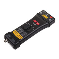
Rigol MSO5000 Series User Manual (42 pages)
High Voltage Differential Probe
Brand:
Rigol
| Category:
Measuring Instruments
| Size: 0.49 MB
Table of Contents
汉语
7
一般安全概要
4
安全术语和符号
6
Table of Contents
7
Rp1000D 系列高压差分探头简介
9
基本操作
12
清洁与保养
13
保修概要
13
技术参数
14
操作环境
17
一般技术规格
17
Guaranty and Declaration
23
General Safety Summary
24
Safety Terms and Symbols
26
English
27
RP1000D Overview
29
Basic Operations
33
Cleaning and General Care
35
Warranty
35
Specifications
36
Technical Specifications
36
General Specifications
39
Operation Environment
39
Accessories
40
Advertisement
Rigol MSO5000 Series Quick Manual (42 pages)
Digital Oscilloscope
Brand:
Rigol
| Category:
Test Equipment
| Size: 3.77 MB
Table of Contents
Guaranty and Declaration
3
Product Certification
3
General Safety Summary
4
Safety Notices and Symbols
4
Care and Cleaning
5
Document Overview
5
General Inspection
7
Product Overview
7
To Prepare for Use
11
To Adjust the Supporting Legs
11
To Connect to AC Power
11
Turn-On Checkout
12
To Set the System Language
12
To Connect the Probe
12
Function Inspection
14
Touch Screen Operation
15
Rectangle Drawing
17
To Use the Built-In Help System
18
Parameter Setting Method
20
Remote Control
22
More Product Information
22
Rigol MSO5000 Series Installation Manual (2 pages)
Kit
Brand:
Rigol
| Category:
Racks & Stands
| Size: 0.33 MB
Advertisement
Related Products
Rigol MSO5000-E Series
Rigol MSO5000-BW1T3
Rigol MSO5000-BW2T3
Rigol MSO5000-BW1T2
Rigol MSO5000-AUTO
Rigol MSO5000-AERO
Rigol MSO5000-COMP
Rigol MSO5000-BW0T1
Rigol MSO5000-AUDIO
Rigol MSO5000-2RL
Rigol Categories
Test Equipment
Measuring Instruments
Power Supply
Portable Generator
Inverter
More Rigol Manuals
Login
Sign In
OR
Sign in with Facebook
Sign in with Google
Upload manual
Upload from disk
Upload from URL