Sign In
Upload
Manuals
Brands
Redline Manuals
Controller
Connect Series
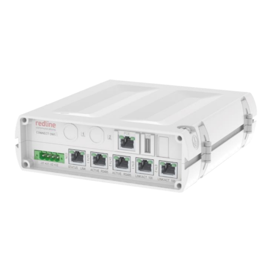
Redline Connect Series Manuals
Manuals and User Guides for Redline Connect Series. We have
3
Redline Connect Series manuals available for free PDF download: Installation Manuallines
Redline Connect Series Installation Manuallines (70 pages)
Brand:
Redline
| Category:
Controller
| Size: 5.13 MB
Table of Contents
Table of Contents
4
Important Notices
9
Important Deployment Information
9
Service & Safety
9
Safety Warnings
9
General Warnings
9
Warning Symbols
9
Installation Safety
10
Professional Installation / Installations Professionnel
10
Safety Precautions
10
Electrocution Hazard / Risque D'électrocution
10
Radio Frequency Safety / Sécurité des Fréquences Radio
11
Personal Safety
11
Electrical Safety
11
Electrical Safety Compliance / Conformité à la Sécurité Electrique
11
Safety Information
12
Lightning Protection / Protection Contre la Foudre
12
Table 1: Notice - Electrical Safety Specifications
12
Table 2: Avis - Spécifications de Sécurité Électrique
12
WEEE Product Return Process
13
Figure 1: Notice - WEEE Logo
13
Service & Warranty Information
14
System Features
15
Figure 2: Features: Connect-OWS System
15
Table 3: Features- Connect-OWS System Components
16
Figure 3: Features: Connect-OWS System Components
16
Connect-OWS System
17
Console Port (CON)
17
Table 4: Features - Pinout con Port - RS-232
17
Table 5: Features - con Port Leds
17
Figure 4: Features: - Connect-OWS Features
17
Serial Interface Ports (DATA 1 & DATA 2)
18
Ethernet Ports (ETH 1 & ETH 2)
18
Table 6: Features - Pinout for Data1 / Data 2 Port 232/485
18
Table 7: Features - DATA Port Leds
18
Figure 5: Description - Connect-OWS DATA 1/2 and con Port Pin Assignment
18
Figure 6: Description - Connect-OWS ETH 1 and ETH 2 Port Pin Assignment
18
Poe Port (Ethernet/Power)
19
Ethernet Ports (ETH 1 & ETH 2)
19
Table 8: Features - Pinout for ETH Ports
19
Table 9: Features - ETH Port Leds
19
Table 10: Features - Pinout for Poe and ETH Ports
19
Table 11: Features - ETH Port Leds
19
Figure 7: Description - Connect-OWS ETH 1 and ETH 2 Port Pin Assignment
19
DC Power Connections
20
Ground Lug
20
Dimensions
20
Table 12: Features - Input Power Connector Pinout
20
Figure 8: Features: - Connect-OWS Dimensions
20
Connect-OW Power Terminal Block
21
Figure 9: Features - Connect-OWS Power Terminal Block
21
Connect-OW Wireless Terminal
22
Connect-OW with Integrated Antenna
22
Connect-OWS-ER (Extended Range) with External Antenna
22
Ethernet Port
22
Figure 10: Features - Connect-OW (Integrated Antenna) Features
22
Figure 11: Features - Connect-OWS-ER (External Antenna) Ethernet Features
22
Ground Lug
23
Table 13: Features: Ethernet Port RJ-45 Pinout (T568B)
23
Figure 12: Description - Connect-OWS Poe Port Pin Assignment
23
Connect-OW Dimensions
24
Ethernet Port Weatherproof Gland
24
Figure 13: Features - Connect-OWS (Integrated Antenna) Dimensions: 8 in
24
Figure 14: Features - Connect-OWS-ER (External Antenna) Dimensions
24
Figure 15: Features - Connect-Ow/Connet-OW-ER Ethernet Gland
24
Ethernet Surge Protection Device
25
Ethernet Port
25
Surge Arrestor Dimensions
25
Figure 16: Features - Ethernet Line Protection Device
25
Figure 17: Features - Ethernet Line Protection Device Dimensions
25
Site Survey
26
General Information
26
Network Settings
26
Table 14: Site Survey - General Information Settings
26
Table 15: Site Survey - Network & Syslog Server Settings
26
Serial Gateway Settings
27
Table 16: Site Survey - Serial Gateway Settings
27
Table 17: Site Survey - Serial Gateway Settings
27
Radio Management Settings
28
Path Profile
28
Table 18: Site Survey - Radio Management Settings
28
Table 19: Site Survey - Path Profile Data
28
Figure 18: Site Survey - RF Planning Fresnel Zone
28
RF Interference
29
Figure 19: Site Survey: Connect-OW Antenna Position
29
Site Preparation
30
General Layout Options
30
Figure 20: Site Survey: Connect-OWS System Layout Options
30
Material Requirements
31
Figure 21: Site Survey: Connect-OWS Site Preparation
31
Review System Grounding Requirements
32
Figure 22: Site Survey: Connect-OWS System Grounding
32
Environmental Conditions (Cabinet/Shelter)
33
Table 20: Site Survey: Operating Temperature Range
33
Figure 23: Site Survey: Connect-OWS Cabinet Equipment
33
Connect-OWS Lead-In Ethernet Connection
34
Cable Length
34
Surge Suppression
34
Weatherproofing
34
Cable Hangars
34
Figure 24: Site Survey: Connect-OWS Lead-In Ethernet Cable
34
Network (Ethernet) Connection
35
Cable Length
35
Surge Suppression
35
Weatherproofing
35
Cable Hangars
35
Figure 25: Site Survey: Connect-OWS Ethernet Network Connection Survey
35
Power Source
36
Isolation
36
Surge Suppression
36
Power Requirments
36
Cable Hangars
36
Table 21: Site Survey: Power Requirements
36
Figure 26: Site Survey: Connect-OWS Power Survey
36
DC Power Supply Wiring
37
Figure 27: Site Survey: Connect-OWS Power Input Wiring
37
Installation
38
Installation Steps
38
Preparation
39
Installation Installation Overview
39
Figure 28: Installation: Connect-OWS System Installation Diagram
39
Materials Supplied by Installer
40
Table 22: Installation: Installer Supplied Materials
40
Assemble Radio Mounting Bracket
41
Standard Pole Mount
41
Figure 29: Installation: Site Survey: Connect-OW Mounting Bracket Assembly
41
Figure 30: Installation: Connect-OW Mounting Bracket Attachment
41
Alternate Mounting Options
42
Figure 31: Installation: Connect-OW Mounting Bracket Alternative Mounting Options
42
Figure 32: Installation: Connect-OW Mounting Bracket Flat-To-Wall Dimensions
42
Assemble and Weatherproof Ethernet Port Connection
43
Ethernet Port Gland
43
Figure 33: Installation: Connect-OW Ethernet Gland Assembly
43
Weatherproof the Ethernet Port
44
Figure 34: Installation: Connect-OW Ethernet Port Weatherproofing
44
Install Outdoor Equipment
45
Install Connect-OWS on Mast
45
Hoist Equipment to Mounting Location
45
Figure 35: Installation: Connect-OW Equipment Mounted with Cabling
45
Cable Hangars
46
Cable Ties
46
Coarse Antenna Alignment
47
Azimuth Alignment
47
Elevation Alignment
47
Install In-Cabinet Equipment
48
Install Connect-OWS Serial Gateway
48
Mounting Options
49
Table 23: Installation: Input Power Connector Pinout
49
Figure 36: Installation: Connect-OWS Power Wiring
49
Figure 37: Features: Connect-OWS Mounting Options
49
Figure 38: Installation: Connect-OWS #10 Ground Lug
50
Install Ethernet Surge Arrestor
51
Figure 39: Installation: Connect-OWS Ethernet Surge Arrestor Wiring
51
Ethernet Jumper Cable
52
Figure 40: Installation: Ethernet Lightning Protection Device
52
Figure 41: Installation: Ethernet Jumper Cable
52
Configure Connect-OWS System
53
Required Materials
53
Table 24: Installation: Installer Supplied Materials
53
Figure 42: Configuration: Connect-OWS System Configuration Block Diagram
53
Accessing Connect-OWS Management Interface
54
Web Browser
54
Figure 43: Configuration: Connect-OWS System Configuration Using PC
54
Figure 44: Configuration: Login Screen
54
Configure the Serial Gateway
55
System Information
55
Figure 45: Configuration: System Information Screen
55
Serial Port Settings
56
Figure 46: Configuration: Serial Port Settings Screen
56
Gateway Settings
57
Figure 47: Configuration: Gateway Settings Screen
57
Radio Management Settings
58
Install Options Key Upgrade (Optional)
58
Network and RF Settings
58
Review and Adjust the Radio Management Parameters as Required. Refer to the Information Collected During the Site Survey
58
Figure 48: Configuration: Product Options Screen
58
Network Settings
59
Serial Gateway Settings
60
Configure System Operating Parameters
61
Required Materials
61
Establish Communications with Test PC
61
Table 25: Configuration: Network and Wireless Settings
61
Table 26: Installation: Installer Supplied Materials
61
Web Browser
62
Figure 49: Configuration: Connect-OWS System Configuration Using PC
62
Telnet Access
63
Install Options Key Upgrade
63
Network and RF Settings
63
Table 27: Configuration: Network and Wireless Settings
63
Figure 50: Configuration: Login Screen
63
Figure 51: Configuration: Product Options Screen
63
Medium/Fine Antenna Alignment
65
Using the Web Alignment Tool (Wireless Terminal Only)
65
Medium Antenna Adjustment Using the Audible Adjustment Tool
65
Figure 52: Configuration: Antenna Alignment Tool Screen
65
Fine Antenna Alignment Using RSSI and SINADR
66
Wireless Terminal Link Status Screen (Wireless Terminal Only)
67
Figure 53: Configuration: Wireless Terminal Link Status Screen
67
Wireless Terminal Links Summary Screen (Base Station Only)
68
Figure 54: Configuration: Wireless Terminal Links Summary Screen
68
Advertisement
Redline Connect Series Installation Manuallines (62 pages)
Brand:
Redline
| Category:
Switch
| Size: 4.46 MB
Table of Contents
Table of Contents
4
Important Notices
8
Important Deployment Information
8
Service & Safety
8
Safety Warnings
8
General Warnings
8
Warning Symbols
8
Installation Safety
9
Professional Installation / Installations Professionnel
9
Safety Precautions
9
Electrocution Hazard / Risque D'électrocution
9
Radio Frequency Safety / Sécurité des Fréquences Radio
10
Personal Safety
10
Electrical Safety
10
Electrical Safety Compliance / Conformité à la Sécurité Electrique
10
Safety Information
11
Lightning Protection / Protection Contre la Foudre
11
Table 1: Notice - Electrical Safety Specifications
11
Table 2: Avis - Spécifications de Sécurité Électrique
11
WEEE Product Return Process
12
Figure 1: Notice - WEEE Logo
12
Service & Warranty Information
13
System Features
14
Figure 2: Features: Connect-IWS System
14
Table 3: Features- Connect-IWS System Components
15
Figure 3: Features: Connect-IWS System Components
15
Connect-IWS System
16
Console Port (CON)
16
Table 4: Features - Pinout con Port - RS-232
16
Table 5: Features - con Port Leds
16
Figure 4: Features: - Connect-IWS Features
16
Serial Interface Ports (DATA 1 & DATA 2)
17
Ethernet Ports (ETH 1 & ETH 2)
17
Table 6: Features - Pinout for Data1 / Data 2 Port 232/485
17
Table 7: Features - DATA Port Leds
17
Figure 5: Description - Connect-IWS DATA 1/2 and con Port Pin Assignment
17
Figure 6: Description - Connect-IWS ETH 1 and ETH 2 Port Pin Assignment
17
DC Power Connections
18
Ground Lug
18
Table 8: Features - Pinout for ETH Ports
18
Table 9: Features - ETH Port Leds
18
Table 10: Features - Input Power Connector Pinout
18
Dimensions
19
Connect-OW Power Terminal Block
19
Figure 7: Features: - Connect-IWS Dimensions
19
Figure 8: Features - Connect-IWS Power Terminal Block
19
MIMO Antenna and RF Cables
20
Figure 9: Features - Connect-IWS 2 Ft In-Cabinet RF Jumper Cable
20
Figure 10: Features - Connect-IWS 25 Ft Outdoor RF Lead-In Cable
20
RF Surge Protection Device
21
Ethernet Port
21
Surge Arrestor Dimensions
21
Figure 11: Features - Ethernet Line Protection Device
21
Figure 12: Features - Ethernet Line Protection Device Dimensions
21
Site Survey
22
General Information
22
Network Settings
22
Table 14: Site Survey - General Information Settings
22
Table 15: Site Survey - Network & Syslog Server Settings
22
Serial Gateway Settings
23
Table 13: Site Survey - Serial Gateway Settings
23
Table 14: Site Survey - Serial Gateway Settings
23
Radio Management Settings
24
Path Profile
24
Table 15: Site Survey - Radio Management Settings
24
Table 16: Site Survey - Path Profile Data
24
Figure 13: Site Survey - RF Planning Fresnel Zone
24
RF Interference
25
Figure 14: Site Survey: Connect-OW Antenna Position
25
Site Preparation
26
General Layout Options
26
Figure 15: Site Survey: Connect-IWS System Layout Options
26
Material Requirements
27
Figure 16: Site Survey: Connect-IWS Site Preparation
27
Review System Grounding Requirements
28
Figure 17: Site Survey: Connect-IWS System Grounding
28
Environmental Conditions (Cabinet)
29
Table 17: Site Survey: Operating Temperature Range
29
Figure 18: Site Survey: Connect-IWS Cabinet Equipment
29
Connect-IWS RF Lead-In Connection
30
Cable Length
30
Surge Suppression
30
Weatherproofing
30
Figure 19: Site Survey: Connect-IWS Lead-In Ethernet Cable
30
Cable Hangars
31
Network (Ethernet) Connection
32
Cable Length
32
Surge Suppression
32
Weatherproofing
32
Cable Hangars
32
Figure 20: Site Survey: Connect-IWS Ethernet Network Connection Survey
32
Power Source
33
Isolation
33
Surge Suppression
33
Power Requirments
33
Cable Hangars
33
Table 18: Site Survey: Power Requirements
33
Figure 21: Site Survey: Connect-IWS Power Survey
33
DC Power Supply Wiring
34
Figure 22: Site Survey: Connect-IWS Power Input Wiring
34
Installation
35
Installation Steps
35
Preparation
36
Installation Overview
36
Figure 23: Installation: Connect-IWS System Installation Diagram
36
Materials Supplied by Installer
37
Table 19: Installation: Installer Supplied Materials
37
Assemble Antenna with Mounting Bracket
38
Connect and Weatherproof RF Lead-In Cables
38
Weatherproof the Antenna Cable Ingress
38
Figure 24: Installation: Connect-IWS Antenna Installation Example
38
Figure 25: Installation: Connect-IWS Antenna Cable Weatherproofing
39
Install Outdoor Equipment
40
Install Antenna on Mast
40
Hoist Antenna to Mounting Location
40
Cable Hangars
40
Cable Ties
40
Figure 26: Installation: Antenna Mounted on Mast
40
Coarse Antenna Alignment
41
Azimuth Alignment
41
Elevation Alignment
41
Install In-Cabinet Equipment
42
Install Connect-IWS
42
Mounting Options
42
Figure 27: Installation: Connect-IWS Power Wiring
42
Table 20: Installation: Input Power Connector Pinout
43
Figure 28: Features: Connect-IWS Mounting Options
43
Figure 29: Installation: Connect-IWS #10 Ground Lug
43
Install RF Surge Arrestors
44
Figure 30: Installation: Connect-IWS RF Surge Arrestor Wiring
44
Figure 31: Installation: RF Surge Protection Device
45
Figure 32: Installation - Connect-IWS 2 Ft In-Cabinet RF Jumper Cable
45
Connect Antenna Lead-In Cables
46
Weatherproof the Antenna Cable Ingress
46
Figure 33: Installation - Connect-IWS Antenna Cable Connection Wiring
46
Figure 34: Installation: Connect-IWS Antenna-Cable Ingress Weatherproofing
47
Configure Connect-IWS System
48
Required Materials
48
Table 21: Installation: Installer Supplied Materials
48
Figure 35: Configuration: Connect-IWS System Configuration Block Diagram
48
Accessing Connect-IWS Management Interface
49
Web Browser
49
Figure 36: Configuration: Connect-IWS System Configuration Using PC
49
Figure 37: Configuration: Login Screen
49
Configure the Serial Gateway
50
System Information
50
Figure 38: Configuration: System Information Screen
50
Serial Port Settings
51
Figure 39: Configuration: Serial Port Settings Screen
51
Gateway Settings
52
Figure 40: Configuration: Gateway Settings Screen
52
Radio Management Settings
53
Install Options Key Upgrade (Optional)
53
Network and RF Settings
53
Review and Adjust the Radio Management Parameters as Required. Refer to the Information Collected During the Site Survey
53
Figure 41: Configuration: Product Options Screen
53
Network Settings
54
Serial Gateway Settings
55
Table 22: Configuration: Network and Wireless Settings
56
Medium/Fine Antenna Alignment
57
Using the Web Alignment Tool (Wireless Terminal Only)
57
Medium Antenna Adjustment Using the Audible Adjustment Tool
57
Figure 42: Configuration: Antenna Alignment Tool Screen
57
Fine Antenna Alignment Using RSSI and SINADR
58
Wireless Terminal Link Status Screen (Wireless Terminal Only)
59
Figure 43: Configuration: Wireless Terminal Link Status Screen
59
Wireless Terminal Links Summary Screen (Base Station Only)
60
Figure 44: Configuration: Wireless Terminal Links Summary Screen
60
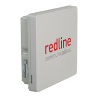
Redline Connect Series Installation Manuallines (58 pages)
Brand:
Redline
| Category:
Touch terminals
| Size: 4.7 MB
Table of Contents
Table of Contents
4
Important Notices
8
Important Deployment Information
8
Service & Safety
8
Safety Warnings
8
General Warnings
8
Warning Symbols
8
Installation Safety
9
Professional Installation / Installations Professionnel
9
Safety Precautions
9
Electrocution Hazard / Risque D'électrocution
9
Radio Frequency Safety / Sécurité des Fréquences Radio
10
Personal Safety
10
Electrical Safety
10
Electrical Safety Compliance / Conformité à la Sécurité Electrique
10
Safety Information
11
Lightning Protection / Protection Contre la Foudre
11
Table 1: Notice - Electrical Safety Specifications
11
Table 2: Avis - Spécifications de Sécurité Électrique
11
WEEE Product Return Process
12
Figure 1: Notice - WEEE Logo
12
Service & Warranty Information
13
System Features
14
Figure 2: Features: Connect-OW System
14
Table 3: Features- Connect-OW System Components
15
Figure 3: Features: Connect-OW System Components
15
Connect-OW Wireless Terminal
16
Connect-OW with Integrated Antenna
16
Connect-OW-ER (Extended Range) with External Antenna
16
Ethernet Port
16
Figure 4: Features - Connect-OW Ethernet Port (Bottom View)
16
Figure 5: Features - Connect-OW-ER Ethernet Port (Bottom View)
16
Ground Lug
17
Table 4: Features: Ethernet Port RJ-45 Pinout (T568B)
17
Figure 6: Description - Connect-OWS Poe Connector Pinout
17
Connect-OW Dimensions
18
Ethernet Port Weatherproof Gland
18
Figure 7: Features - Connect-OW Dimensions
18
Figure 8: Features - Connect-OW-ER Dimensions
18
Figure 9: Features - Ethernet Port - Metal Weatherproof Connector Assembly
18
Power over Ethernet (Poe) Device
19
DC-DC Poe
19
Ethernet Port
19
Poe Port
19
Table 5: Features - Pinout for POE and ETH Ports
19
Figure 10: Features - DC-DC Poe Features
19
Figure 11: Description - POE ETH Port Pin Assignment
19
LED Indicators
20
Table 6: Features: DC-DC Poe LED Indicators
20
DC Power Connections
21
Ground Lug
21
Table 7: Features: DC-DC Poe Power Connections
21
Figure 12: Features - Connect-OW DC-DC Poe Power Terminal Block
21
Figure 13: Features - DC-DC Poe Ground Lug
21
Poe Dimensions
22
Figure 14: Features - DC-DC Poe Dimensions
22
AC-DC Poe
23
Figure 15: Features - AC-DC Poe - Indoor Power Module Pinout
23
Ethernet Surge Protection Device
24
Ethernet Port
24
Surge Arrestor Dimensions
24
Figure 16: Features - Ethernet Line Protection Device
24
Figure 17: Features - Ethernet Line Protection Device Dimensions
24
Site Survey
25
General Information
25
Network Settings
25
Radio Management Settings
25
Table 8: Site Survey - General Information Settings
25
Table 9: Site Survey - Network & Syslog Server Settings
25
Table 10: Site Survey - Radio Management Settings
25
Path Profile
26
Table 11: Site Survey - Path Profile Data
26
Figure 18: Site Survey - RF Planning Fresnel Zone
26
RF Interference
27
Figure 19: Site Survey: Connect-OW Antenna Position
27
Site Preparation
28
General Layout Options
28
Figure 20: Site Survey: System Layout Options
28
Material Requirements
29
Figure 21: Site Survey: Site Preparation
29
Review System Grounding Requirements
30
Figure 22: Site Survey: System Grounding
30
Environmental Conditions (Cabinet/Shelter)
31
Table 12: Site Survey: Operating Temperature Range
31
Figure 23: Site Survey: Cabinet Equipment
31
Connect-OW Lead-In Ethernet Connection
32
Cable Length
32
Surge Suppression
32
Weatherproofing
32
Cable Hangars
32
Figure 24: Site Survey: Connect-OW Lead-In Ethernet Cable
32
Network (Ethernet) Connection
33
Cable Length
33
Surge Suppression
33
Weatherproofing
33
Cable Hangars
33
Figure 25: Site Survey: Network Connection Ethernet Cable
33
Power Source
34
Isolation
34
Surge Suppression
34
Power Requirments
34
Cable Hangars
34
Table 13: Site Survey: Power Requirements
34
Figure 26: Site Survey: Power Wiring
34
Installation
35
Installation Steps
35
Preparation
36
Installation Installation Overview
36
Figure 27: Installation: Connect-OW System Completed Installation
36
Materials Supplied by Installer
37
Table 14: Installation: Installer Supplied Materials
37
Assemble Radio Mounting Bracket
38
Standard Pole Mount
38
Figure 28: Installation: Mounting Kit - Assemble Bracket Arm
38
Figure 29: Installation: Mounting Kit - Attach Arm to Connect-OW
38
Alternate Mounting Options
39
Figure 30: Installation: Mounting Kit - Alternative Mounting Methods
39
Figure 31: Installation: Mounting Kit - Flat-To-Wall Dimensions
39
Assemble and Weatherproof Ethernet Port Connection
40
Ethernet Port Gland
40
Figure 32: Installation: Ethernet Port Gland Assembly
40
Weatherproof the Ethernet Port
41
Figure 33: Installation: Ethernet Port Weatherproofing
41
Install Outdoor Equipment
42
Install Connect-OW on Mast
42
Hoist Equipment to Mounting Location
42
Figure 34: Installation: Mounted with Cabling
42
Cable Hangars
43
Cable Ties
43
Coarse Antenna Alignment
44
Azimuth Alignment
44
Elevation Alignment
44
Install In-Cabinet Equipment
45
Install Poe Power Injector
45
Figure 35: Installation: Poe Power Wiring
45
Table 15: Installation: Input Power Connector Pinout
46
Figure 36: Installation: Poe DIN Rail Mount
46
Figure 37: Installation: Poe Power Connections
46
Figure 38: Installation: Poe Ground Lug
47
Install Ethernet Surge Arrestor
48
Figure 39: Installation: Ethernet Surge Arrestor Wiring
48
Ethernet Jumper Cable
49
Figure 40: Installation: Ethernet Line Protection Device
49
Figure 41: Installation: Ethernet Jumper Cable
49
Configure System Operating Parameters
50
Required Materials
50
Establish Communications with Test PC
50
Table 16: Installation: Installer Supplied Materials
50
Figure 42: Configuration: Connect-OW System Configuration Using PC
50
Web Browser
51
Telnet Access
51
Install Options Key Upgrade
51
Figure 43: Configuration: Login Screen
51
Network and RF Settings
52
Table 17: Configuration: Network and Wireless Settings
52
Figure 44: Configuration: Product Options Screen
52
Medium/Fine Antenna Alignment
53
Using the Web Alignment Tool (Wireless Terminal Only)
53
Medium Antenna Adjustment Using the Audible Adjustment Tool
53
Figure 45: Configuration: Antenna Alignment Tool Screen
53
Fine Antenna Alignment Using RSSI and SINADR
54
Wireless Terminal Link Status Screen (Wireless Terminal Only)
55
Figure 46: Configuration: Wireless Terminal Link Status Screen
55
Wireless Terminal Links Summary Screen (Base Station Only)
56
Figure 47: Configuration: Wireless Terminal Links Summary Screen
56
Advertisement
Advertisement
Related Products
Redline Connect-OWS
Redline Speed Smoke
Redline Connect-IWS
Redline Categories
Security Sensors
Control Unit
Touch terminals
Radio
Lifting Systems
More Redline Manuals
Login
Sign In
OR
Sign in with Facebook
Sign in with Google
Upload manual
Upload from disk
Upload from URL