Redline Connect Series Installation Manuallines
Hide thumbs
Also See for Connect Series:
- Installation manuallines (58 pages) ,
- Installation manuallines (62 pages)
Table of Contents
Advertisement
Virtual Fiber™
Outdoor Wireless TCP/IP Transport
Universal Wireless Transport™
Connect-OWS System
Installation Guidelines
1
Important Notices ................................................................... 9
2
System Features ................................................................... 15
3
Site Survey ............................................................................ 26
4
Installation ............................................................................ 38
70-00200-02-00
Connect Series
(UWT™) System for SCADA
Proprietary Redline Communications © 2014
Page
1
of 70
December 3, 2014
Advertisement
Table of Contents

Related Manuals for Redline Connect Series


Summary of Contents for Redline Connect Series
- Page 1 Connect Series Universal Wireless Transport™ (UWT™) System for SCADA Connect-OWS System Installation Guidelines Important Notices ..............9 System Features ..............15 Site Survey ................26 Installation ................38 70-00200-02-00 Proprietary Redline Communications © 2014 Page of 70 December 3, 2014...
- Page 2 All rights reserved December 3, 2014. The information in this document is proprietary to Redline Communications Inc. This document may not in whole or in part be copied, reproduced, or reduced to any medium without prior consent, in writing, from Redline Communications Incorporated.
- Page 3 CONNECT-OWS Installation Guidelines Revision Log Date Item Description of Changes 20141121 Created Document 70-00200-02-00 Proprietary Redline Communications © 2014 Page of 70 December 3, 2014...
-
Page 4: Table Of Contents
Connect-OW Dimensions ................24 Ethernet Port Weatherproof Gland ..............24 Ethernet Surge Protection Device ..............25 Ethernet Port ....................25 Surge Arrestor Dimensions ................25 Site Survey ................26 70-00200-02-00 Proprietary Redline Communications © 2014 Page of 70 December 3, 2014... - Page 5 Weatherproof the Ethernet Port ..............44 Install Outdoor Equipment ................45 4.2.1 Install Connect-OWS on Mast ................. 45 Hoist Equipment to Mounting Location ............45 Cable Hangars ..................... 46 70-00200-02-00 Proprietary Redline Communications © 2014 Page of 70 December 3, 2014...
- Page 6 Table 2: Avis - Spécifications de sécurité électrique ............12 Table 3: Features- Connect-OWS System Components ..........16 Table 4: Features - Pinout CON Port - RS-232 .............. 17 70-00200-02-00 Proprietary Redline Communications © 2014 Page of 70 December 3, 2014...
- Page 7 Figure 20: Site Survey: Connect-OWS System Layout Options ........30 Figure 21: Site Survey: Connect-OWS Site Preparation ..........31 Figure 22: Site Survey: Connect-OWS System Grounding ..........32 70-00200-02-00 Proprietary Redline Communications © 2014 Page of 70 December 3, 2014...
- Page 8 Figure 52: Configuration: Antenna Alignment Tool Screen ..........65 Figure 53: Configuration: Wireless Terminal Link Status Screen ........67 Figure 54: Configuration: Wireless Terminal Links Summary Screen ......68 70-00200-02-00 Proprietary Redline Communications © 2014 Page of 70 December 3, 2014...
-
Page 9: Important Notices
General Warnings Redline recommendations for maximum safety include the following: Do not operate microwave equipment without first having proper training or knowledge of microwave radio operation. -
Page 10: Installation Safety
Redline microwave radio equipment or those recommended by Redline. Electrocution Hazard / Risque D’électrocution Warning to Service Personnel Do not install Redline products near any type of power line. Should the antenna or related hardware come in contact with power lines, severe bodily harm or death could result! 70-00200-02-00 Proprietary Redline Communications ©... -
Page 11: Radio Frequency Safety / Sécurité Des Fréquences Radio
Installation Guidelines Attention au personnel du service Ne pas installer les produits Redline près n'importe quel type de ligne électrique. Si votre antenne ou du matériel connexe entrer en contact avec des lignes électriques, des blessures graves ou la mort pourraient en résulter! Radio Frequency Safety / Sécurité... -
Page 12: Safety Information
70-00200-02-00 Proprietary Redline Communications © 2014 Page of 70 December 3, 2014... -
Page 13: Weee Product Return Process
WEEE Product Return Process In accordance with the WEEE (Waste from Electrical and Electronic Equipment) directive, 2002/96/EC, Redline Communications equipment is marked with the logo shown below. The WEEE directive seeks to increase recycling and re-use of electrical and electronic equipment. This symbol indicates that this product should not be disposed of as part of the local municipal waste program. -
Page 14: Service & Warranty Information
Redline does not endorse or support the use of outdoor cable assemblies: i) not supplied by Redline, ii) third-party products that do not meet Redline's cable and connector assembly specifications, or iii) cables not installed and weatherproofed as specified in the CONNECT-OWS Installation Guidelines manual for each product model. -
Page 15: System Features
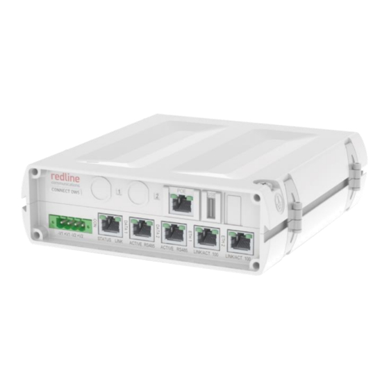
CONNECT-OWS Installation Guidelines Chapter 2 System Features The Connect-OWS system is designed and manufactured by Redline Communications, a world leader in design and production of outdoor wireless TCP/IP transport for mission critical applications. Figure 2: Features: Connect-OWS System 70-00200-02-00 Proprietary Redline Communications © 2014... -
Page 16: Table 3: Features- Connect-Ows System Components
Mounting kit includes mounting bracket with assembly hardware (assembly required). Fits 25 - 105 mm (1.0 - 4.25 in) mast pipe or mounts on a flat surface. Ethernet port gland (weatherproofing). 70-00200-02-00 Proprietary Redline Communications © 2014 Page of 70 December 3, 2014... -
Page 17: Connect-Ows System
Error: no radio detected or other internal error Power is off (or sleep mode) Radio Ok - Wireless link is up Link Blink Radio OK - Wireless link is down Radio is off 70-00200-02-00 Proprietary Redline Communications © 2014 Page of 70 December 3, 2014... -
Page 18: Serial Interface Ports (Data 1 & Data 2)
The ETH 1 and ETH 2 ports (RJ-45 socket) are 10/100Base-T Ethernet interface ports for customer use. Figure 6: Description - Connect-OWS ETH 1 and ETH 2 Port Pin Assignment 70-00200-02-00 Proprietary Redline Communications © 2014 Page of 70 December 3, 2014... -
Page 19: Poe Port (Ethernet/Power)
Table 11: Features - ETH Port LEDs Description Link active - no data flow LINK ACT Blink Link active - data flow detected Link not active 100Base-T mode 10Base-T mode 70-00200-02-00 Proprietary Redline Communications © 2014 Page of 70 December 3, 2014... -
Page 20: Dc Power Connections
All Connect-OWS systems must be properly grounded. Dimensions The Connect-OWS dimensions are: (h-w-d) 51 x 174.7 x 181 mm (2 x 6.88 x 7.13 in). Figure 8: Features: - Connect-OWS Dimensions 70-00200-02-00 Proprietary Redline Communications © 2014 Page of 70 December 3, 2014... -
Page 21: Connect-Ow Power Terminal Block
Connect-OW Power Terminal Block The Connect-OWS 4-position power terminal block provides a convenient method to terminate the DC supply wiring. Figure 9: Features - Connect-OWS Power Terminal Block 70-00200-02-00 Proprietary Redline Communications © 2014 Page of 70 December 3, 2014... -
Page 22: Connect-Ow Wireless Terminal
The Ethernet port (RJ-45 / F connector) receives DC power and provides Ethernet connectivity with the local network. The Ethernet port connects to the PoE adapter using a weatherproof CAT-5e Ethernet cable. 70-00200-02-00 Proprietary Redline Communications © 2014 Page of 70 December 3, 2014... -
Page 23: Ground Lug
Connect-OWS chassis. Use this connection to terminate a grounding wire. All Connect-OWS systems must be properly grounded to protect against power surges and accumulated static electricity. 70-00200-02-00 Proprietary Redline Communications © 2014 Page of 70 December 3, 2014... -
Page 24: Connect-Ow Dimensions
A weatherproof gland is provided for the Connect-OWS Ethernet port. The Connect- OWS Ethernet port must have this gland installed and properly weatherproofed. Figure 15: Features - Connect-OW/Connet-OW-ER Ethernet Gland 70-00200-02-00 Proprietary Redline Communications © 2014 Page of 70 December 3, 2014... -
Page 25: Ethernet Surge Protection Device
Surge Arrestor Dimensions The surge arrestor dimensions (h-d-w) are: 44 x 54 x 34 mm (1.33 x 2.13 x 1.73 in). Figure 17: Features - Ethernet Line Protection Device Dimensions 70-00200-02-00 Proprietary Redline Communications © 2014 Page of 70 December 3, 2014... -
Page 26: Site Survey
Table 15: Site Survey - Network & Syslog Server Settings Setting Serial Gateway Radio Management Network DHCP Enable IP Address Subnet Mask IP Gateway Address DNS Server 1 DNS Server 2 Syslog Settings Enable Syslog Server IP 70-00200-02-00 Proprietary Redline Communications © 2014 Page of 70 December 3, 2014... -
Page 27: Serial Gateway Settings
Data Packing Packet Length Force Transmit (msec) Enable Delimiter 1 Delimiter 1 (value) Enable Delimiter 2 Delimiter 2 (value) Delimiter Action TCP Server Settings Local TCP Port Max. Connections 70-00200-02-00 Proprietary Redline Communications © 2014 Page of 70 December 3, 2014... -
Page 28: Radio Management Settings
(NLOS) path using RF signal reflections, such as a common reflective structure (e.g., large building) that is LOS for the antennas of communicating units. 70-00200-02-00 Proprietary Redline Communications © 2014 Page of 70 December 3, 2014... -
Page 29: Rf Interference
RF channel. Use the built-in spectrum sweep feature to determine if a selected RF channel is generally free from interference. 70-00200-02-00 Proprietary Redline Communications © 2014 Page of 70 December 3, 2014... -
Page 30: Site Preparation
The distance from the in-cabinet PoE to the Connect-OWS terminal is limited by the 91.5 m (300 ft) restriction for the total length of the Ethernet cable. Figure 20: Site Survey: Connect-OWS System Layout Options 70-00200-02-00 Proprietary Redline Communications © 2014 Page of 70 December 3, 2014... -
Page 31: Material Requirements
Figure 21: Site Survey: Connect-OWS Site Preparation Important: Diagram is for informational purposes only. Installer may adjust for company standards and industry Best Practices in effect at site location. 70-00200-02-00 Proprietary Redline Communications © 2014 Page of 70 December 3, 2014... -
Page 32: Review System Grounding Requirements
Ensure all grounding complies with local electrical standards. The grounding wire may be secured using the cable hanger stack. Figure 22: Site Survey: Connect-OWS System Grounding 70-00200-02-00 Proprietary Redline Communications © 2014 Page of 70 December 3, 2014... -
Page 33: Environmental Conditions (Cabinet/Shelter)
Connect-OWS In-cabinet -40 to 75 °C (-40 to 167 °F) Surge In-cabinet -40 to 85 °C (-40 to 185 °F) Suppression Figure 23: Site Survey: Connect-OWS Cabinet Equipment 70-00200-02-00 Proprietary Redline Communications © 2014 Page of 70 December 3, 2014... -
Page 34: Connect-Ows Lead-In Ethernet Connection
The installer must provide suitable cable hangars for the CAT-5 outdoor Ethernet cable, spaced at a recommended maximum of 450 -610 mm (~18 - 24 in). 70-00200-02-00 Proprietary Redline Communications © 2014 Page of 70 December 3, 2014... -
Page 35: Network (Ethernet) Connection
The installer must provide suitable cable hangars for the CAT-5 outdoor Ethernet cable, spaced at a recommended maximum of 450 -610 mm (~18 - 24 in). 70-00200-02-00 Proprietary Redline Communications © 2014 Page of 70 December 3, 2014... -
Page 36: Power Source
The installer must provide suitable cable hangars for the power cable, spaced at a recommended maximum of 450 -610 mm (~18 - 24 in). 70-00200-02-00 Proprietary Redline Communications © 2014 Page of 70 December 3, 2014... -
Page 37: Dc Power Supply Wiring
The following diagram illustrates the wiring for a primary and secondary DC supply. Figure 27: Site Survey: Connect-OWS Power Input Wiring Notes: Best practices recommend twisting the DC supply wires. 70-00200-02-00 Proprietary Redline Communications © 2014 Page of 70 December 3, 2014... -
Page 38: Installation
2. Install Ethernet Surge Arrestor 4.4 Configure System Operating Parameters 1. Required Materials 2. Establish Communications with Test PC 3. Install Options Key 4. Network and RF settings 5. Medium/Fine antenna Adjustment 70-00200-02-00 Proprietary Redline Communications © 2014 Page of 70 December 3, 2014... -
Page 39: Preparation
The following diagram illustrates a completed Connect-OWS installation. Review this diagram to become familiar with all requirements for a successful installation. Figure 28: Installation: Connect-OWS System Installation Diagram 70-00200-02-00 Proprietary Redline Communications © 2014 Page of 70 December 3, 2014... -
Page 40: Materials Supplied By Installer
A CAT-5e RJ-45 jumper cable to connect the Connect-OWS to the PC. * Note: Cabinet and Connect-OWS system may be mounted on the same mast (based on site survey results). 70-00200-02-00 Proprietary Redline Communications © 2014 Page of 70 December 3, 2014... -
Page 41: Assemble Radio Mounting Bracket
Assemble the mounting bracket in the standard method to mount the Connect-OWS on masts 44 - 72 mm (1.57 - 3.00 in) in diameter. Figure 29: Installation: Site Survey: Connect-OW Mounting Bracket Assembly Figure 30: Installation: Connect-OW Mounting Bracket Attachment 70-00200-02-00 Proprietary Redline Communications © 2014 Page of 70 December 3, 2014... -
Page 42: Alternate Mounting Options
CONNECT-OWS Installation Guidelines Alternate Mounting Options Figure 31: Installation: Connect-OW Mounting Bracket Alternative Mounting Options Figure 32: Installation: Connect-OW Mounting Bracket Flat-to-Wall Dimensions 70-00200-02-00 Proprietary Redline Communications © 2014 Page of 70 December 3, 2014... -
Page 43: Assemble And Weatherproof Ethernet Port Connection
4.1.4 Assemble and Weatherproof Ethernet Port Connection The Redline outdoor Ethernet cable is terminated with a non-hooded RJ-45 connector. This connects to the metal RJ-45 connector located on the wireless terminal enclosure. When connecting the outdoor Ethernet cable to the wireless terminal, ensure the RJ-45 plug is fully inserted and locked into the socket. -
Page 44: Weatherproof The Ethernet Port
Seal both ends of the assembly with cable ties to prevent unravelling of the PVC tape. Do not over-tighten the cable ties, as this may compromise the weather seal. This completes the weatherproofing procedure. Figure 34: Installation: Connect-OW Ethernet Port Weatherproofing 70-00200-02-00 Proprietary Redline Communications © 2014 Page of 70 December 3, 2014... -
Page 45: Install Outdoor Equipment
Important: Do not use the Ethernet cable to hoist the terminal. If the Ethernet cable has been connected and weatherproofed, create the service loop and securely attach cable to the mounting bracket to avoid any strain on the Ethernet port connection during 70-00200-02-00 Proprietary Redline Communications © 2014 Page of 70 December 3, 2014... -
Page 46: Cable Hangars
CAT-5 outdoor Ethernet cable, spaced at a recommended maximum of 450 mm (~18 in). Cable Ties If using plastic cable ties -- do not over-tighten. 70-00200-02-00 Proprietary Redline Communications © 2014 Page of 70 December 3, 2014... -
Page 47: Coarse Antenna Alignment
(spirit) level. This method is not accurate for elevation settings of greater than 5 degrees. To adjust the elevation, loosen the appropriate bolts of the mounting bracket. 70-00200-02-00 Proprietary Redline Communications © 2014 Page of 70 December 3, 2014... -
Page 48: Install In-Cabinet Equipment
Ethernet cable from the customer equipment to the wireless terminal is 91.5 m (300 ft). The ground lug on the Connect-OWS device is internally connected to the ground pin on the front panel pluggable terminal block (GND). 70-00200-02-00 Proprietary Redline Communications © 2014 Page of 70 December 3, 2014... -
Page 49: Mounting Options
+Ve power input #2 Ground Lug A #10 ground-lug is provided on the Connect-OWS chassis. Use this connection to terminate a grounding wire. All Connect-OWS systems must be properly grounded. 70-00200-02-00 Proprietary Redline Communications © 2014 Page of 70 December 3, 2014... -
Page 50: Figure 38: Installation: Connect-Ows #10 Ground Lug
CONNECT-OWS Installation Guidelines Figure 38: Installation: Connect-OWS #10 Ground Lug 70-00200-02-00 Proprietary Redline Communications © 2014 Page of 70 December 3, 2014... -
Page 51: Install Ethernet Surge Arrestor
Do not install surge protection equipment during adverse weather conditions when the threat of a lightning strike is possible. Overview of Surge Arrestor Wiring Figure 39: Installation: Connect-OWS Ethernet Surge Arrestor Wiring 70-00200-02-00 Proprietary Redline Communications © 2014 Page of 70 December 3, 2014... -
Page 52: Ethernet Jumper Cable
This is a standard 'straight-through' Ethernet cable. It is recommended to provide a shielded cable with shielded connectors. Figure 41: Installation: Ethernet Jumper Cable 70-00200-02-00 Proprietary Redline Communications © 2014 Page of 70 December 3, 2014... -
Page 53: Configure Connect-Ows System
Table 24: Installation: Installer Supplied Materials Item Description Cabinet Portable computer with Web browser. Ethernet Cable crossover A CAT-5e cable terminated with RJ-45 at both ends. 70-00200-02-00 Proprietary Redline Communications © 2014 Page of 70 December 3, 2014... -
Page 54: Accessing Connect-Ows Management Interface
On the PC, open a browser and enter the unit wireless terminal IP address in the browser address bar. The default address and credentials are: IP Address: 192.168.25.12 User Name: admin Password: admin Figure 44: Configuration: Login Screen 70-00200-02-00 Proprietary Redline Communications © 2014 Page of 70 December 3, 2014... -
Page 55: Configure The Serial Gateway
Save All. Note that changing to another screen discards all unsaved changes. System Information Review and adjust the following parameters as required. Figure 45: Configuration: System Information Screen 70-00200-02-00 Proprietary Redline Communications © 2014 Page of 70 December 3, 2014... -
Page 56: Serial Port Settings
CONNECT-OWS Installation Guidelines Serial Port Settings Review and adjust the following Serial Port parameters as required. Figure 46: Configuration: Serial Port Settings Screen 70-00200-02-00 Proprietary Redline Communications © 2014 Page of 70 December 3, 2014... -
Page 57: Gateway Settings
Important: The items in the table are required for basic installation. Based on the Options Key installed, other features may be available that require configuration. Refer to the RDL-3000 Family User Manual for additional information. 70-00200-02-00 Proprietary Redline Communications © 2014 Page of 70 December 3, 2014... -
Page 58: Radio Management Settings
The General Information fields uniquely identify each installed system. It is recommended to record this information prior to installation. Table 14: Site Survey - General Information Settings Setting Serial Gateway Radio Management Name Details Location 70-00200-02-00 Proprietary Redline Communications © 2014 Page of 70 December 3, 2014... -
Page 59: Network Settings
Table 15: Site Survey - Network & Syslog Server Settings Setting Serial Gateway Radio Management Network DHCP Enable IP Address Subnet Mask IP Gateway Address DNS Server 1 DNS Server 2 Syslog Settings Enable Syslog Server IP 70-00200-02-00 Proprietary Redline Communications © 2014 Page of 70 December 3, 2014... -
Page 60: Serial Gateway Settings
Data Packing Packet Length Force Transmit (msec) Enable Delimiter 1 Delimiter 1 (value) Enable Delimiter 2 Delimiter 2 (value) Delimiter Action TCP Server Settings Local TCP Port Max. Connections 70-00200-02-00 Proprietary Redline Communications © 2014 Page of 70 December 3, 2014... -
Page 61: Configure System Operating Parameters
RJ-45 at both ends. 4.9.2 Establish Communications with Test PC The wireless terminal can be configured and monitored using standard Web browser (e.g., Firefox or Internet Explorer) or a Telnet client. 70-00200-02-00 Proprietary Redline Communications © 2014 Page of 70 December 3, 2014... -
Page 62: Web Browser
The default wireless address is: 192.168.25.2 Netmask: 255.255.255.0 Login to the wireless terminal using the assigned username and password. The default credentials are: Username: admin Password: admin 70-00200-02-00 Proprietary Redline Communications © 2014 Page of 70 December 3, 2014... -
Page 63: Telnet Access
To save changes click Apply & Save All. Note that changing to another screen discards all unsaved changes. Table 27: Configuration: Network and Wireless Settings Screen Parameter Description 70-00200-02-00 Proprietary Redline Communications © 2014 Page of 70 December 3, 2014... - Page 64 Important: The items in the table are required for basic installation. Based on the Options Key installed, other features may be available that require configuration. Refer to the RDL-3000 Family User Manual for additional information. 70-00200-02-00 Proprietary Redline Communications © 2014 Page of 70 December 3, 2014...
-
Page 65: Medium/Fine Antenna Alignment
Open a Telnet session on the test PC and login to the wireless terminal. Use the following command to enable the audible alignment tool. The audible alignment signal remains active until this field is disabled. 70-00200-02-00 Proprietary Redline Communications © 2014 Page of 70 December 3, 2014... -
Page 66: Fine Antenna Alignment Using Rssi And Sinadr
Note: For non-LOS deployments, a suitable reflecting surface such as a building or billboard must be used. It is necessary to perform vertical and horizontal sweeps of the antenna to determine if the required throughput can be achieved. 70-00200-02-00 Proprietary Redline Communications © 2014 Page of 70 December 3, 2014... -
Page 67: Wireless Terminal Link Status Screen (Wireless Terminal Only)
RSSI: Received signal strength indicator. SINADR: Average signal to interference, noise, and distortion ratio. Figure 53: Configuration: Wireless Terminal Link Status Screen 70-00200-02-00 Proprietary Redline Communications © 2014 Page of 70 December 3, 2014... -
Page 68: Wireless Terminal Links Summary Screen (Base Station Only)
UL: Received signal strength to noise measured by this unit. RSSI [dBm]: Received signal strength indicator. DL: RSSI reported by the remote end unit. UL: Received signal strength measured by this unit. 70-00200-02-00 Proprietary Redline Communications © 2014 Page of 70 December 3, 2014... - Page 69 CONNECT-OWS Installation Guidelines 70-00200-02-00 Proprietary Redline Communications © 2014 Page of 70 December 3, 2014...
- Page 70 Virtual Fiber™ Outdoor Wireless TCP/IP Transport 302 Town Centre Markham, Ontario Canada L3R 0E8 www.rdlcom.com 70-00200-02-00 Proprietary Redline Communications © 2014 Page of 70 December 3, 2014...
Need help?
Do you have a question about the Connect Series and is the answer not in the manual?
Questions and answers