Sign In
Upload
Manuals
Brands
Pepperl+Fuchs Manuals
Gateway
VBG-EN-K30-DMD-S16
Pepperl+Fuchs VBG-EN-K30-DMD-S16 Manuals
Manuals and User Guides for Pepperl+Fuchs VBG-EN-K30-DMD-S16. We have
1
Pepperl+Fuchs VBG-EN-K30-DMD-S16 manual available for free PDF download: Manual
Pepperl+Fuchs VBG-EN-K30-DMD-S16 Manual (154 pages)
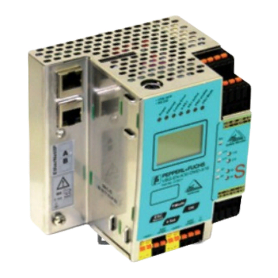
EtherNet/IP Gateway with integrated Safety Monitor
Brand:
Pepperl+Fuchs
| Category:
Gateway
| Size: 5.36 MB
Table of Contents
Table of Contents
3
Conformity Statement
8
1 Symbol Catalog
9
Abbreviations
9
2 General
10
Product Information
10
Brief Description
11
3 Safety
12
Safety Standard
12
Intended Use
12
Conditions of Use
12
Residual Risks (en 292-1)
12
Areas of Application
12
Organizational Requirements
13
Documentation
13
Traceability of the Devices
13
Safety Regulations
13
Qualified Personnel
14
Repair
14
Disposal
14
4 Spezifications
15
Technical Data
15
Data Sheet VBG-EN-K30-DMD-S16
15
Safety-Relevant Characteristic Data
17
System Reaction Times - Example Calculations
18
Scope of Delivery
21
5 Installation
22
Dimensions
22
Connections
22
Installing in the Control Cabinet
23
Removing
23
Electrical Connection
24
Commissioning
25
Switching to Advanced Display Mode
25
Setting of Ethernet Properties
25
Connecting AS-I Slaves
26
Quick Setup
27
Error Tracing
28
Faulty Slaves
28
Error Display (Last Error)
28
Addressing
29
Assigning Address 6 to Slave Currently at Address 2
29
Replacing a Defective AS-I Safety Slave
30
Replacing the Chip Card
31
Local Parameter Setting of Safe AS-I/Gateways and Monitors
32
Safe Configuration Using ASIMON 3 G2
34
6 Maintenance
36
Checking for Safe Turn-Off
36
7 Electrical Connection
37
Overview of Terminals, Indicators and Operating Elements
37
Vbg-En-K30-DMD-S16
37
AS-I Bus Connection
38
Information about the Device Types
38
AS-I and Power Supply Terminal Assignments
38
Electrical Connection VBG-EN-K30-DMD-S16
39
Diagnostics Interface
40
Diagnostics Port RS 232
40
Chip Card
40
Ethernet/Ip Interface
40
Release Circuits
41
Wiring Overview of Safety Monitor
41
Indicators and Operating Elements
42
LED Indicators - Master
42
LED Indicators - Monitor
43
Buttons
44
8 Function and Startup of the Safety Monitor
45
Powering up the Device
45
Configuration of the Safety Functions
45
Description of Configuration Using ASIMON 3 G2 Software
46
Description of Configuration Using Chip Card with Master Configuration
47
Configuration Using a Chip Card with Complete Configuration
47
Safety-Relevant Documentation of the Application
48
Diagnostic Data
48
Switch-Off History
49
Password Protection
49
Procedure for Configuring and Teaching Code Sequences
49
Function of the Esc/Service Key
50
Safe Coupling Slaves on the AS-I Circuits
51
Chip Card
51
Unsafe Data
51
Card Unformatted
51
Data Not Compatible
52
Card Empty
52
Data Compatible
52
Data in the Device and on the Chip Card Identical
52
Data in the Device and on the Chip Card Not Identical
52
Safe Data
53
Data Incompatible
53
Data Compatible
54
Complete Configuration
54
Data on the Chip Card and in the Device Are Identical
54
Data Not Identical
55
Operating the Chip Card from the Menu
55
Working with Multiple Memory Banks
55
9 Operation in Advanced Display Mode
57
Overview
57
Navigating through the Advanced Display Mode
61
ETHERNET/IP (Main Menu)
62
TCP/IP Object
62
If Status
62
If Capability
63
If Control
63
Path to Link Object
64
Tcp/Ip Config
64
Ethernet Object
65
Quick Setup
66
As-I Safety
67
Teach Codes
68
Teach Codes - Complete
68
Single Slave
70
Coupling Slave
71
Input Code Seq
72
SAFE OUTPUT CH (Channels for the Release Circuits)
72
SAFE COUPLING (Optional Menu)
73
START/STOP (Changing the Monitor Mode)
73
CLEAR SAFE CFG (Delete Safe Configuration)
74
PIN (Changing the PIN)
74
Safe Chipcard
75
VIEW BANK X CONFIG (View Active Bank)
76
CARD ->MONITOR (Copy Card Data to the Monitor)
77
MONITOR ->CARD (Copy Monitor Data to the Chip Card)
78
CLEAR CODES (Delete Code Sequences)
80
Clear Safe Card
81
PROTECT (Protect Safe Configuration)
82
SAFETY SUBST VAL (Substitute Values for Input Data from Safe Slaves)
82
Diagnostics
83
AS-I CIRCUIT (Selecting the AS-I Circuit)
84
SAFETY SLAVES (Safety Oriented Slaves)
84
INT MON (Internal Monitor)
85
DIAGNOSTICS (Diagnostics for the Internal Monitor)
85
LAST DIAGNOSIS (Last Diagnostics for the Int. Monitor)
86
MONITOR CONFIG (Configuration of the Int. Monitor)
88
EXT SAFETY MON (External Monitor)
88
DIAGNOSE (Diagnosis for the External Monitor)
89
LAST DIAGNOSIS (Last Diagnostics for the External Monitor)
90
ACTUAL CONFIG (Configuration for the External Monitor)
91
Fault Detector
92
Delta List
93
LCS (History of the Slaves Which Have Triggered a Configuration Error)
93
Error Counters
94
LPF (List of Peripheral Faults)
95
Flags
95
ACTUAL CONFIG (Actual Slave Configuration)
97
AS-I MASTER (Info)
98
Slave Adr Tool
99
TEST (Test Tools for Slaves)
100
AS-I CIRCUIT (Selecting the AS-I Circuit)
100
Slave Test Tool
101
Binary Inputs
102
Binary Outputs
102
Analog Inputs
102
Analog Outputs
103
Parameter
104
SETUP (Configuration of the AS-I Network)
104
AS-I CIRCUIT 1
105
Operation Mode
105
STORE ACTUAL (Store Currently Detected Configuration)
105
FORCE OFFLINE (Switch AS-I Master to Offline Operation)
106
AUTO ADDR ENABLE (Enable Automatic Address)
106
AS-I ADDRESS (AS-I Address Assistant)
107
AS-I CONTROL (Optional)
107
CONTROL INFO (Status of the Control Program)
108
CONTROL RUN (Start or Stop the Control Program)
108
CONTROL FLAGS (Control Program Flag Memory)
109
LOS (List of Offline Slaves)
109
Chipcard
110
Language (Menu Language)
110
FACTORY RESET (Factory Default Settings)
110
DISPLAY CONTRAST (Set Display Contrast)
111
10 Advanced Diagnostics for AS-I Masters
112
List of Corrupted AS-I Slaves (LCS)
112
Protocol Analysis: Counters for Corrupted Data Telegrams
112
Offline Phase for Configuration Errors
113
Functions of the AS-I Fault Detector
113
Duplicate Address Detection
113
Earth/Ground Fault Detector
114
Noise Detector
114
Over-Voltage Detector
114
11 Ethernet/Ip Interface
115
Objekt Modelling
115
Identity Object
116
Assembly Object
117
AS-I Master Object
120
AS-I Slave Object
122
I/O Data Object
123
Advanced Diagnostics Object
127
Short Command Interface Object
128
Long Command Interface Object
128
Safety Control Status Internal Monitor
128
Safety Control Status External Monitor
130
12 Appendix: the First Commissioning with Compactlogix
132
Working with Sample Files
135
13 Data Transfer Using CIP Messages in Rslogix5000
136
MSG Instruction and Message Type Tag
136
Example 1: Read las
138
Example 2: Read/Write 16-Bit (Analog) Data
139
14 System Startup Using AS-I Control Tools
140
15 Configuration with Windows Software ASIMON 3 G2
143
16 Status Indication, Faults and Fault Elimination
144
Spontaneous Display of Faults from the Safety Unit
144
Replacing a Defective Safety-Configured AS-I Slave
145
Replacing a Defective AS-I Safety Monitor
146
Forget the Password? What Do I Do Now
146
17 Glossary
148
18 Appendix: Example of a Bidirectional Safety Coupling
151
19 Reference List
153
Manual: "ASIMON 3 G2 Configuration Software
153
Sources
153
Advertisement
Advertisement
Related Products
Pepperl+Fuchs VBG-ENXK20-DMD-EV
Pepperl+Fuchs VBG-ENXK20-DMD
Pepperl+Fuchs VBG-ENXK20-D
Pepperl+Fuchs VBG-EN-K20-D
Pepperl+Fuchs VBG-EN-K20-MD
Pepperl+Fuchs PROFINET VBG-EP1-KE5-D Series
Pepperl+Fuchs VBG-PN-K20-D-BV
Pepperl+Fuchs VBG-PN-K20-DMD-EV
Pepperl+Fuchs VBG-PN-K30-DMD-S16-EV
Pepperl+Fuchs VBG-PN-K30-DMD-S16
Pepperl+Fuchs Categories
Accessories
Security Sensors
Control Unit
Industrial Equipment
Switch
More Pepperl+Fuchs Manuals
Login
Sign In
OR
Sign in with Facebook
Sign in with Google
Upload manual
Upload from disk
Upload from URL