Sign In
Upload
Manuals
Brands
Pepperl+Fuchs Manuals
Gateway
VBG-PN-K30-DMD-S16
Pepperl+Fuchs VBG-PN-K30-DMD-S16 Manuals
Manuals and User Guides for Pepperl+Fuchs VBG-PN-K30-DMD-S16. We have
1
Pepperl+Fuchs VBG-PN-K30-DMD-S16 manual available for free PDF download: Manual
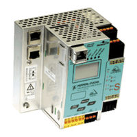
Pepperl+Fuchs VBG-PN-K30-DMD-S16 Manual (130 pages)
AS-I 3.0 PROFINET GATEWAY WITH INTEGR. SAFETY MONITOR
Brand:
Pepperl+Fuchs
| Category:
Gateway
| Size: 7.3 MB
Table of Contents
Table of Contents
3
1 Introduction
8
2 Declaration of Conformity
9
3 Safety
10
Symbols Relevant to Safety
10
General Notes on Safety
10
Disposal
10
4 General
11
Product Information
11
AS-I 3.0 Gateway PROFINET Via Profisafe
12
New Generation of AS-I Gateways with Ethernet Diagnostics Interface
13
Brief Description
14
5 Specifications - AS-I/Profinet Gateways
16
Technical Data
16
Safety-Relevant Characteristic Data
17
Overview of Parameter for Determining the Failure Rates
18
Reaction Times
19
Sensor -> Local Relay Output
19
Sensor -> Local Electronic Output
19
Sensor -> AS-I Relay Output
20
Sensor -> AS-I Electronic Output
20
System Reaction Times - Example Calculations
21
Scope of Delivery
24
6 Specifications - AS-I/Profisafe Gateway
25
Technical Data
25
Safety-Relevant Characteristic Data
26
Reaction Times
27
Ethernet (Profisafe) -> Local Relay Output
27
Ethernet (Profisafe) -> Local Electronic Output
27
Ethernet (Profisafe) -> AS-I Relay Output
28
Ethernet (Profisafe) -> AS-I Electronic Output
28
7 Installation
29
Dimensions
29
Connections
29
Installing in the Control Cabinet
30
Removing
30
Commissioning
31
Switching to Advanced Display Mode
31
Setting the PROFINET Properties
31
Setting the Profisafe Address
32
Connecting AS-I Slaves
33
Quick Setup
34
Error Tracing
35
Faulty Slaves
35
Error Display (Last Error)
35
Addressing
36
Assigning Address 15 to Slave Currently at Address 2
36
Local Parameter Setting of Safe AS-I Gateways and Monitors
37
Replacing a Defective Safety-Related AS-I Slave
39
Replacing the Chip Card
40
Replacing a Defective Device
40
Teaching the Group Manager after Replacing a Device
43
Replacing the Monitor
44
Safe Configuration Using ASIMON 3 G2
47
8 Maintenance
49
Checking for Safe Turn-Off
49
9 Electrical Connection
50
Overview of Terminals, Indicators and Operating Elements
50
AS-I Bus Connection
51
Information about the Device Types
51
AS-I and Power Supply Terminal Assignments
51
Electrical Connection VBG-PN-K30-D-S16
52
Electrical Connection VBG-PN-K30-DMD-S16-EV
53
Electrical Connection VBG-PN-K30-DMD-S16, VBG-PNS-K30-DMD
54
Diagnostics Interface
55
Diagnostics Port RS 232
55
PROFINET Interface
55
Safe Coupling Via Ethernet
56
Chip Card
56
Release Circuits
57
Wiring Overview - Safety Unit
57
Indicators and Operating Elements
58
LED Indicators - Master
58
LED Indicators - Safety Unit
59
Buttons
60
10 Function and Startup of the Safety Monitor
61
Powering up the Device
61
Configuration of the Safety Functions
61
Description of Configuration Using ASIMON 3 G2 Software
62
Description of Configuration Using Chip Card with Master Configuration
63
Configuration Using a Chip Card with Complete Configuration
63
Safety-Relevant Documentation of the Application
64
Diagnostic Data
64
Diagnostics of Release Circuits 1-4 Via the Binary Data
65
Switch-Off History
65
Diagnostic Values in the IDI
66
Password Protection
67
Procedure for Configuring and Teaching Code Sequences
68
Function of the Esc/Service Key
69
Safe Coupling Slaves on the AS-I Circuits
69
Chip Card
69
Unsafe Data
69
10.8.1.1 Card Unformatted
69
10.8.1.2 Data Not Compatible
70
10.8.1.3 Card Empty
70
10.8.1.4 Data Compatible
70
10.8.1.5 Data in the Device and on the Chip Card Identical
70
10.8.1.6 Data in the Device and on the Chip Card Not Identical
70
Safe Data
71
10.8.2.1 Data Incompatible
71
10.8.2.2 Data Compatible
71
10.8.2.3 Complete Configuration
72
10.8.2.4 Data on the Chip Card and in the Device Are Identical
72
10.8.2.5 Data Not Identical
72
10.8.2.6 Operating the Chip Card from the Menu
73
Working with Multiple Memory Banks
73
11 Operation in Advanced Display Mode
75
12 Advanced Diagnostics for AS-I Masters
76
List of Corrupted AS-I Slaves (LCS)
76
Protocol Analysis: Counters for Corrupted Data Telegrams
76
Offline Phase for Configuration Errors
77
Functions of the AS-I Fault Detector
77
Duplicate Address Detection
77
Earth/Ground Fault Detector
78
Noise Detector
78
Over-Voltage Detector
78
Functions of the New Generation of AS-I Gateways
79
C-Programmable Gateways
79
Interchangeable Memory Card
79
Earth Fault Monitor
79
Current Can be Read Directly on the Unit
80
Self-Resetting Fuses
81
AS-I Power24V Capable
81
Ethernet Diagnostics Interface with Web Server
82
Transitionless Operating Mode Changes
82
13 Configuration of AS-I/Profinet Gateways
83
Projecting PROFINET Network
83
Logical Slots
83
Options
83
Bytes Digital AS-I I/O Data (a and B Slaves)
86
Bytes Digital AS-I I/O Data (a Slaves Only)
88
Bytes Digital AS-I I/O Data (B Slaves Only)
88
Words Analog AS-I Input Data
89
Words Analog AS-I Output Data
91
Bytes Command Interface
92
Bytes Command Interface
93
Byte Command Interface
94
Executing of Command Interface Commands
94
PROFINET Diagnostics
95
Channel Error Codes
95
Manufacturer Specific Diagnostic
96
Safety Control/Status
99
Diagnostics in the Cyclic Channel (10 Byte Safelink.diag.)
101
Device-Specific Parameters
102
Media Redundancy Protocol MRP
103
14 System Startup Using AS-I Control Tools
104
15 Configuration with Windows Software ASIMON 3 G2
107
16 Status Indication, Faults and Fault Elimination
108
Spontaneous Display of Faults from the Safety Unit
108
Replacing a Defective Safety-Configured AS-I Slave
109
Replacing a Defective AS-I Safety Monitor
110
Forget the Password? What Do I Do Now
110
17 Safe Link
112
General Introduction
112
Configuration
113
Configuration Using ASIMON
114
Diagnostics
115
18 Glossary
117
19 Appendix, Examples
120
Startup on a Siemens NC Control
120
Setting in the S7 Configuration
120
Setting in the NC Control
121
Setting "PROFISAFE_IN_ADDRESS
121
Setting "PROFISAFE_OUT_ADDRESS
121
Setting "PROFISAFE_IN_ASSIGN
121
Setting "PROFISAFE_OUT_ASSIGN
122
Setting "PROFISAFE_IN_FILTER
122
Setting "PROFISAFE_OUT_FILTER
122
Safety Diagnostics in the Input Data Image (IDI)
123
Representation of the Diagnostic Information
123
Other Representation Variants
124
Changing the Default Setting
124
20 Reference List
127
Manual: "ASIMON 3 G2 Configuration Software
127
Sources
127
21 Codes Indicated by the Display
128
Advertisement
Advertisement
Related Products
Pepperl+Fuchs VBG-PN-K30-DMD-S16-EV
Pepperl+Fuchs VBG-PN-K30-D-S16
Pepperl+Fuchs VBG-PN-K20-D-BV
Pepperl+Fuchs VBG-PN-K20-DMD-EV
Pepperl+Fuchs VBG-PNS-K30-DMD
Pepperl+Fuchs VBG-PB-K25
Pepperl+Fuchs VBG-PB-K20-DMD-C1
Pepperl+Fuchs VBG-EN-K20-MD
Pepperl+Fuchs VBG-DN-K20-DMD
Pepperl+Fuchs PROFINET VBG-EP1-KE5-D Series
Pepperl+Fuchs Categories
Accessories
Security Sensors
Control Unit
Industrial Equipment
Switch
More Pepperl+Fuchs Manuals
Login
Sign In
OR
Sign in with Facebook
Sign in with Google
Upload manual
Upload from disk
Upload from URL