Sign In
Upload
Manuals
Brands
OMRON Manuals
Inverter
RX - 2
OMRON RX - 2 High-Performance Inverter Manuals
Manuals and User Guides for OMRON RX - 2 High-Performance Inverter. We have
4
OMRON RX - 2 High-Performance Inverter manuals available for free PDF download: User Manual, Instruction Manual, Datasheet
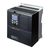
Omron RX - 2 User Manual (920 pages)
High-function General-purpose Inverter
Brand:
Omron
| Category:
Inverter
| Size: 21 MB
Table of Contents
Introduction
3
Intended Readers
3
Notice
3
Manual Configuration
4
Manual Structure
5
Page Structure and Symbol Icons
5
Special Information
6
Sections in this Manual
7
Terms and Conditions Agreement
8
Warranty, Limitations of Liability
8
Application Considerations
9
Disclaimers
9
Safety Precautions
10
Indications and Meanings of Safety Information
10
Explanation of Symbols
11
Precautions for Correct Use
12
Precautions for Safe Use
14
Precautions for Correct Use
16
Regulations and Standards
18
Items to Check after Unpacking
19
Checking the Nameplate
19
Checking the Model
20
Checking the Accessories
21
Related Manuals
22
Revision History
23
Table of Contents
24
Contents
25
Overview
33
Section 1 Overview
34
Overview of Functions
34
Features of 3G3RX2 Series Inverter
34
Classes of 3G3RX2 Series Inverter
37
Compliance with International Standards
38
Appearance and Part Names
39
Specifications
40
Standard Specifications
40
Class Specifications
43
V Class Specifications
44
External Dimensions
45
Restrictions
53
Design
58
Installation
58
Inverter Installation
58
Precaution for Installation
58
Installation Environment
61
Removal of each Part
70
Removing Cover
70
Terminal Blocks
71
Preparing Backing Plate
72
Wiring
74
Standard Connection Diagram
74
Arrangement and Function of Main Circuit Terminal Block
75
Arrangement and Function of Control Circuit Terminal Block
76
Wiring for Main Circuit Terminals
86
Wiring for Control Circuit Terminals
113
Wiring for PG Option Unit
117
Wiring for RS485-Communication Terminals
125
Wiring for Digital Operator
127
Wiring for STO Function
127
Conditions of Conformity of EU Directives
129
Compatibility Conditions of UL/CSA Standards
131
Korean Radio Regulation (KC)
134
Reference Manual for Options
134
Operation
137
Overview of LCD Operator
139
Part Names and Descriptions
139
Names of Operation Keys
140
LCD Display
141
Transition of Screen Display
147
How to Set Battery and the Time Setting
148
Parameter Settings
150
Scroll Mode
150
Concurrent Monitor Mode
154
Monitor Function
157
Three-Line Monitor Screen
157
Setting Screen "Concurrent Monitor
158
Monitor with Large Characters
159
Error History Display
160
Trip History
160
Retry History
161
Data Copy Function
163
Read Function
163
Write Function
164
System Settings
166
Contents
168
Changing the Data Indicated at the Bottom Center
168
Parameter Function
169
Parameter Preservation Function
169
Limiting Displayed Parameters
170
Saving Automatically Changed Parameters
180
Protecting Parameters by Password
181
Display Fixation Function
183
Error Operation on the LCD Operator
184
Selection of Operation at Disconnection of LCD Operator
184
Display of Battery Level Warning
184
Preventing Read and Write of Unnecessary Data
185
Inverter Initialization
186
Connection and Functions of CX-Drive
191
CX-Drive Connection Method
191
Outline of CX-Drive
195
Section 4 Test Run
200
Test Run Method
200
Settings and Commands Required for Running the Inverter
201
Operation Only with LCD Operator
203
Conduct a Test Run with Analog Input
205
Simulation Mode
208
Monitor
211
Section 5 Monitor
213
Frequency Monitor
213
Output Frequency Monitor
213
Frequency Command Monitor
214
Frequency Conversion Monitor
215
Speed Detection Value Monitor
216
Acceleration/Deceleration Time Monitor
217
Operation Direction Monitor
218
I/O Terminal Monitor
219
Input Terminal Monitor
219
Output Terminal Monitor
219
Output Current Monitor
220
Output Voltage Monitor
220
P-N Voltage Monitor
221
Operation Time and Count Monitor
222
Cumulative Operating Hours Monitor During RUN
222
Cumulative Power-On Time Monitor
222
Total Start-Up Count Monitor
222
Cumulative Power-On Count Monitor
223
Cooling Fin Temperature Monitor
224
Power Monitor
225
Input Power Monitor
225
Output Power Monitor
226
Life Monitor
227
Life Diagnostic Monitor
227
Monitor of Cumulative Operating Time of Cooling Fan
228
Electronic Thermal Load Ratio Monitor
229
Electronic Thermal Load Ratio Monitor of Motor
229
Electronic Thermal Load Ratio Monitor of Inverter
229
Inverter Rated Monitor
230
Load Rated Monitor
230
Rated Current Monitor
230
Braking Resistor Load Ratio Monitor
231
Inverter Status Monitor
232
Analog Input Value Monitor
234
Analog Terminal Setting Monitor
235
Terminal Block Type Monitor
236
Operation Command/Frequency Command Sources Monitor
237
Options Monitor
238
6-1 Basic Parameter Settings
241
Inverter Load Rating Settings
241
Basic Parameter Settings
241
Inverter Initialization
243
Parameter Setting for Motor Related
246
Motor Basic Settings
246
Motor Constant Setting
250
Auto-Tuning of Motor
252
Operation Command Settings
257
Types of Operation Commands
257
Operation with LCD Operator
257
Operation with Forward/Reverse Rotation Terminal
258
Operation with 3 Wire Function of Terminal Block
259
Operation with RS485 Communication
260
Operation from Optional Unit
260
Disabling the Keys on LCD Operator
261
Temporary Change of Operation Command Destination
262
Frequency Command Settings
263
Frequency Command Selection
263
Case Where Command Is Given with LCD Operator
264
Case Where Command Is Given from Terminal Block Analog Signals
265
Case Where Command Is Given through RS485 Communications
266
Case Where Command Is Given through Input of Pulse String
266
Case Where Command Is Given through Driveprogramming
272
Case Where Command Is Given with PID Control
272
Case Where Command Is Given with Main Speed Command and Auxiliary Speed Command
273
Case Where Command Is Given with Multi-Step Speed
275
Temporal Addition of Frequency Command
279
Up/Down Function (FUP, FDN)
279
Analog Command Hold Function (AHD)
280
Temporal Change of Frequency Command Destinations
281
Limit Frequency and Operation Commands
282
Limit Operation Command Direction
283
Limit Output Direction
283
Operation Permission
284
Thermal Protection of Motor (Electronic Thermal)
286
Electronic Thermal Setting
286
Monitoring of Motor Temperature
293
Acceleration/Deceleration Settings
294
Change Acceleration Time and Deceleration Time
294
Switch Acceleration Time and Deceleration Time in Two Stages
296
Switching of Acceleration or Deceleration Time with Multi-Speed Step
299
Holding Function of Acceleration/Deceleration
304
Change the Acceleration or Deceleration Pattern
305
Following Frequency Command
308
Overview of Motor Control Methods
311
Selection of Motor Control Methods
313
V/F Control (Constant Torque Characteristics)
313
V/F Control (Reducing Torque Characteristics)
314
V/F Control (Free V/F)
315
Energy-Saving Mode
318
Manual Torque Boost
319
Automatic Torque Boost
320
Stabilization of Motor Rotation
322
Sensorless Vector Control
323
Zero-Speed Range (Zero-Hz Range) Sensorless Vector Control
325
Vector Control with Sensor
327
Synchronous Motor (Permanent Magnet Motor) Control
330
V/F Control with Sensor (Constant Torque Characteristics)
340
V/F Control with Sensor (Reducing Torque Characteristics)
341
Free V/F Control with Sensor
342
Automatic Torque Boost Control with Sensor
344
Encoder Feedback Control
345
Torque Control
351
Control Gain Switching Function
351
Speed Control and Torque Control
351
P/PI Switching Function
354
Torque Limit Function
356
High-Torque Multi-Operation Control
360
Torque Bias Function
362
Switching Function of Torque Control/Speed Control (ATR)
364
Torque Command
364
Torque Command
365
Reduction of Motor Noise, Noise and Inverter Heat Generation
367
Carrier Frequency
367
Automatic Carrier Reduction
368
Lowering Electromagnetic Noise from Motor
370
Start Conditions
371
Selection of Reduced Voltage Startup
371
Startup DC Injection Braking
372
Frequency Matching Start
373
Frequency Pull-In Start
377
Starting after Power-On
381
Restart after Releasing Reset
382
Starting after Free-Run Stop
384
Forcing Function
386
Startup DC Injection Braking (Servo Lock Control)
388
Stop Conditions
390
Selection of Stop Operation
390
DC Injection Braking Stop
391
DC Braking for Stopping (Servo Lock Control)
398
Applied Settings
401
PID Control
404
Function Overview
404
PID Parameter and Block Diagram
407
PID Soft-Start Function
419
PID Sleep Function
421
PID2/PID3/PID4 Control
424
PID Signal Output
433
PID Unit Change
436
Tripless Functions
440
Section 7 Advanced Settings
311
7-1 Overview of Motor Control Methods
313
Section 8 Applied Settings
404
Overload Limit Level Function
440
Overcurrent Suppression Selection
442
Overvoltage Suppression Function During Deceleration
444
Overexcitation Function
447
Regenerative Braking Function
450
Restart During Power Interruption/Undervoltage
452
Restart on Overvoltage/Overcurrent
458
Non-Stop on Momentary Power Interruption
463
Protective Functions
469
Input Power Supply Phase Loss Protection
469
Output Phase Loss Protection Function
469
External Trip (EXT) Function
470
Power Recovery Restart Prevention Function (USP)
471
Overcurrent Detection
471
Instantaneous Power Interruption/Undervoltage Detection
472
Overcurrent Detection
472
Frequency Jump Function
477
Speed Deviation Error Detection
478
Overspeed Error Detection
479
Control Function
480
2Nd Control (SET)
480
Commercial Switch (CS)
481
Jogging Operation Function (JG)
483
Brake Control Function (BRK)
485
Contactor Control (CON)
491
Forced Operation
494
Pulse Train Position Control
499
Orientation Control
505
Absolute Position Control
508
Servo Lock (SON)
520
Cooling Fan Control
522
Alarm Signal
523
Alarm Signal (AL)
523
Fatal Fault Signal (MJA)
525
Alarm Code
526
Overload Warning Function (OL/OL2)
527
Low Current Signal (LOC)
529
Momentary Power Interruption Signal (IP)
531
Signal During Undervoltage (UV)
532
Motor Thermal Warning Signal (THM)
533
Inverter Thermal Warning Signal (THC)
534
Cooling Fin Overheat Warning Signal (OHF)
535
Capacitor Life Warning Signal (WAC)
536
Cooling Fan Life Warning Signal (WAF)
536
RUN Time over Signal (RNT)
537
Power on Time over Signal
538
Incoming Overvoltage Signal (OVS)
539
Terminal Output During Run
540
Signal During RUN (RUN)
540
Signal During RUN (FWR/RVR)
541
Starting Contact Signal
542
Operation Ready (IRDY)
543
Frequency Arrival Signal (FA1 to FA5)
544
Output Signal on Constant Speed Arrival (FA1)
544
Set Frequency Exceeded Signal (FA2/FA4)
545
Set Frequency Matched Signal (FA3/FA5)
546
0-Hz Detection Signal (ZS)
547
Applied Output
548
Analog Disconnection Signal
548
Logical Output Signal
551
Input Terminal Function
554
Overview
554
Input Terminal Selections
555
Input Terminal Response Time
558
Reset
559
Analog Input
563
Pulse Count Function
567
Automatic Reset Function
570
Output Terminal Function
573
Overview
573
Output Terminal NO/NC Selections
575
Output Terminal on Delay/Off Delay
577
Analog Output Terminal Adjustment
578
Analog Output Terminal Switch Settings
581
Output Functions (FM)
585
Communications Functions
593
Communication Specifications
594
Modbus Method
597
Explanation of each Function Code
601
Saving a Change to Holding Register (Enter Command)
611
Modbus Communication Register Number List
613
Coil Number List
613
Group D Register List
615
Group F Register List
632
Group a Register List
634
Group B Register List
656
Group C Register List
664
Group H Register List
673
Group P Register List
681
Group U Register List
683
Group O Register List
687
Inter-Inverter Communication
689
Inter-Inverter Communication Parameters
690
Communication Settings
693
Driveprogramming
695
Overview of Driveprogramming
696
Overview of Optional Equipment
701
Part Names and Descriptions
701
Regenerative Braking Unit (Model: 3G3AX-RBU)
703
Specifications
703
External Dimensions
705
Connection Examples
710
Braking Resistor (Model: 3G3AX-RBA/RBB/RBC)
711
Specifications
711
External Dimensions
712
Connection Example
714
Regenerative Braking Unit and Braking Resistor Combination Selection Table
715
DC Reactor (Model: 3G3AX-DL)
722
Section 9 Communications Functions
594
Section 10 Driveprogramming
696
Section 11 Options
701
Specifications
722
External Dimensions
724
Connection Examples
727
AC Reactor (Model: 3G3AX-AL)
728
Specifications
728
External Dimensions
730
Connection Examples
731
Input Noise Filter (Model: 3G3AX-NFI)
732
Specifications
732
External Dimensions
734
Connection Examples
739
Output Noise Filter (Model: 3G3AX-NFO)
740
Specifications
740
External Dimensions
742
Connection Example
743
Radio Noise Filter (Model: 3G3AX-ZCL)
744
Specifications
744
External Dimensions
745
Connection Example
746
11-10EMC Noise Filter (Model: 3G3AX-EFI )
747
Specifications
747
EMC Noise Filter (Model: 3G3AX-EFI)
747
External Dimensions
749
Connection Example
752
Digital Operator Cable (Model: 3G3AX-OPCN)
753
Specifications
753
Troubleshooting
755
Checking Alarm Display
756
Checking Trip Information
756
Checking Retry Information
757
Procedure for Resetting Trip State
758
Error No. and Its Measure
759
Error No. Table
759
Details about Errors
761
Alarm Display and Its Measures
777
Checking Alarm Display
777
Checking Inconsistent Settings
783
Checking Message
784
Troubleshooting
786
Maintenance and Inspection
795
Daily Inspection
796
Periodic Inspection
797
Inspection Items
798
Cleaning
802
Test Methods
803
Megger Test
803
Pressure Test
803
Checking Method of Inverter and Converter
804
Measurement Method of I/O Voltage, Current, and Power
806
Smoothing Capacitor Life Curve
807
Life Alarming Output
808
Appendices a Technical Information
810
Comparison of External Dimensions
810
Parameter Comparison
818
Overview of Inverter Selection
833
Appendices B STO Function
837
Overview of STO Function
838
B-1-1 Response Time
839
B-1-2 Self-Diagnosis of Internal Path
839
B-1-3 STO Input
839
B-1-4 Monitoring Output (EDM Output) of STO Status
839
B-1-5 Periodic Function Test
839
B-1-6 Safety Function
839
B-1-7 Response Time
839
B-1-8 Safety Related Parameter
840
Procedure for Use of STO Function
841
B-2-1 STO Signal Input
841
B-2-2 Retaining Requirements of STO Status
843
B-2-3 STO Confirmation Signal Output (EDM Signal
843
B-2-4 Timing Chart
844
B-2-5 Status Indication Function
845
Example of Use
848
Example of Wiring
848
External Device
848
Appendices C Table of Parameters
849
Parameter Notation
850
Monitor List
852
Parameter List
869
Advertisement
Omron RX - 2 User Manual (176 pages)
DriveProgramming, CX-Drive
Brand:
Omron
| Category:
Inverter
| Size: 3 MB
Table of Contents
Introduction
3
Manual Configuration
4
Manual Structure
5
Sections in this Manual
7
Table of Contents
8
Contents
9
Terms and Conditions Agreement
11
Safety Precautions
12
Precautions for Safe Use
15
Regulations and Standards
16
Related Manuals
17
Revision History
18
Overview
19
Overview of Driveprogramming
20
Preparation and System Configuration
22
Specifications
23
Operation Procedure for Driveprogramming
27
Operation Procedure
28
Parameters Related to Driveprogramming
31
Program Structure
36
Tasks
36
Subroutines
36
Task Processing
36
Driveprogramming Start/Stop and Task Operation
38
Driveprogramming Restart
40
Task Operation on Trip
41
Driveprogramming Editor
44
Starting Driveprogramming Editor
44
Parts of Driveprogramming Editor
48
Driveprogramming Editor
48
Toolbar
48
Driveprogramming Area
51
Toolbox Window
55
Block Parameters Window
56
Properties Window
57
Error List Tab in Output Window
58
Adding, Deleting and Renaming Tasks
59
Inserting, Deleting and Calling Subroutines
60
Creating Flowchart Programs
61
Creating Text Programs
62
Editing Transferred (Uploaded) Programs
63
Saving Programs
64
Transferring and Verifying Programs
66
Executing Programs (Driveprogramming Function Selection)
67
4-11 Other Useful Functions
70
Driveprogramming User Variables
75
User Variables and User Parameters
76
Input/Output Terminal Variables
79
Timer Variables
84
Inverter Setting Variables
86
Inverter Monitor Variables
88
Input Variables
92
Output Variables
95
Driveprogramming Commands
97
Command Categories
98
Command Format
99
Command List
100
Program Control Commands
106
Arithmetic Operation and Logical Operation Commands
119
I/O Control Commands
132
Timer Control Commands
143
Parameter Control Commands
149
Inverter Control Commands
153
Inverter Parameters Affected by Setting Order
162
Parameters Affected by Rated Current [%]
166
Parameters Affected by PID Enabled/Disabled
168
Troubleshooting
172
Driveprogramming Operation on Error
172
Driveprogramming Operation on Error Reset
173
Alarm Code List
174
Omron RX - 2 Instruction Manual (88 pages)
Brand:
Omron
| Category:
Inverter
| Size: 7 MB
Table of Contents
Instruction Manual
45
Terms and Conditions Agreement
46
Warranty, Limitations of Liability
46
Safety Precautions
48
Explanation of Symbols
48
Precautions for Safe Use
51
Installation and Storage
51
Transportation, Installation, and Wiring
51
Operation and Adjustment
52
Maintenance and Inspection
52
Precautions for Correct Use
53
Installation and Wiring
53
Inverter Specifications
55
Common Specification
57
Applicable Standards
58
Installation Conditions
62
Main Circuit
64
Control Circuit
70
Input Terminals
71
Specifications
81
Advertisement
OMRON RX - 2 Datasheet (22 pages)
Brand:
OMRON
| Category:
Inverter
| Size: 2 MB
Table of Contents
System Configuration
4
Specifications
5
Type Designation
5
Common Specifications
6
Resistor Dimensions
12
Standard Connections
13
Terminal Block Specifications
13
Control Circuit
14
Braking Unit
16
Ordering Information
17
Advertisement
Related Products
Omron RX-A2004
Omron RX-A2015
Omron RX-A2037
Omron RX-A2220
Omron RX-A2450
Omron RX-A2550
Omron RX-A4110
Omron RX-A4150
Omron RX-A4450
Omron RX-A4550
OMRON Categories
Blood Pressure Monitor
Controller
Accessories
Switch
Inverter
More OMRON Manuals
Login
Sign In
OR
Sign in with Facebook
Sign in with Google
Upload manual
Upload from disk
Upload from URL