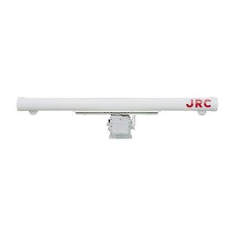
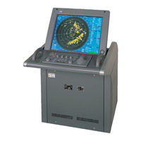
Sign In
Upload
Manuals
Brands
JRC Manuals
Marine Radar
JMA-9922-6XA
JRC JMA-9922-6XA Manuals
Manuals and User Guides for JRC JMA-9922-6XA. We have
3
JRC JMA-9922-6XA manuals available for free PDF download: Instruction Manual, Service Manual
JRC JMA-9922-6XA Instruction Manual (404 pages)
Marine Radar Equipment
Brand:
JRC
| Category:
Marine Radar
| Size: 7.69 MB
Table of Contents
3. Basic Operation
18
General and Equipment Composition
17
Table of Contents
18
Control Panel Switches
59
Section 3 Basic Operation
72
3 Basic Operation
72
Flow of Operation
73
Power on and Start the System
74
Observe and Adjust Video
76
Tuning Operations
79
Acquire and Measurement Data
80
End the Operation and Stop the System
80
Menu Coposition
81
Menu Composition
81
Preparation
84
Display Brilliance Control
84
Sensitivity Control [GAIN]
84
Tuning [TUNE]
84
Tuning[Tune]
84
Contrast Control [BRILL VIDEO]
85
Sea Clutter Suppression [RAIN]
85
Sea Clutter Suppression [SEA]
85
Brilliance Control
86
Rain/Snow Clutter Suppression [RAIN]
86
Color Setting [COLOR]
94
Day/Night Mode Selection [DAY/NIGHT]
94
Basic Operations
106
Methods for Setting Menu Items with the Trackball
106
Move Cross Cursor Mark [+] by Trackball
106
Use Ebls (Electronic Bearing Lines)
113
Use Ebls(Electronic Bearing Lines)
113
Set Floating EBL
115
Set Floating EBL
117
Select Range [RANGE]
119
Set Maximum Range
119
Select Bearing Display Mode [AZI MODE]
120
Select Pulse Length
120
Cancel All Display Items Except HL and Cross Cursor Mark [+] [DATA OFF]
121
Cancel Ship's Heading Line [HL OFF]
121
Display PI (Parallel Index Lines) [PI]
122
Display Pi(Parallel Index Lines )[PI]
122
Move Own Ship's Display Position [OFF CENTER]
125
Display Other Ship's Trails [TRAILS]
126
Display Own Ship's Tracks and Own Symbols[Own SHIP]
127
Display Own Ship's Tracks and Own Symbols [OWN TRACK]
127
Marking [MARK]
130
Display Range Rings [RANGE RINGS]
131
Display Variable Range Markers [VRM1/VRM2]
131
Vrm Operation
132
Set Guard Zones [GUARD ZONE]
133
Reset Alarm Buzzer [ALARM ACK]
135
Set Alarm Sound Level
135
Function
137
Expand Targets
138
Display Processed Videos
139
Reduce Radar Interference
140
Personal Information
141
Display of Navigational Information
144
Function of USER Switch / OPTION Switch
160
Operation of Performance Monitor
161
EBL Maneuvering
167
Section 4 Measurement of Range and Bearing
172
4 Measurement of Range and Bearing
172
Measurement by Trackball
173
Measurement by Ebls and Vrms
174
Measurement by Range Rings
174
Measurement between Two Optional Points
176
Section 5 Operation of Arpa
179
Using ARPA
180
Initial Setting
181
Setting Collision Decision Criteria: SAFE LIMIT
181
Automatic Setting Mode (System Start)
183
Setting Range Scale : RANGE SCALE
183
Setting Range Scale: RANGE SCALE
183
Setting Own Ship's Speed
184
Display Mode Setting
186
Setting Bearing Display Mode [AZI MODE]
186
Setting Motion Display Mode [TM/RM]
186
TARGET ID No. DISPLAY
187
Target Acquisition
188
Automatic Acquisition [AUTO]
188
Manual Acquisition [MANUAL]
190
Use of Automatic and Manual Acquisition Modes [GZ1• a GZ2]
191
Arpa Data Display
192
Display of Vectors
192
Guard Zone
194
Display of Past Positions [PAST POSN]
195
Data Display
197
Types of Data Display
197
Cancellation of Displaying Target Data [TGT DATA]
198
Method of Displaying Target Data [TGT DATA]
198
Alarm Display
199
Dangerous Target Alarm: CPA/TCPA
199
Guard Zone Alarm [GUARD ZONE]
200
Lost Target Alarm [LOST TARGET]
201
Gyro Set Alarm [SET GYRO]
202
System Function Alarm [ARPA (DATA)]
202
Trial Maneuvering
203
Trial Maneuvering in the True Vector Mode
203
Trial Maneuvering in the Relative Vector Mode
204
Using the TRIAL Function
205
Deleting Unwanted Targets
206
Deleting Targets
206
Deleting Targets
207
Arpa Setting
208
Simulation
209
Gate Size
211
Test Video
213
6 True and False Echoes on Display
215
Radar Wave with the Horizon
217
Strength of Reflection from the Target
219
Sea Clutters
219
False Echoes
219
Display of Radar Transponder (SART)
222
Section 7 Maintenance
223
7 Maintenance
223
Routine Maintenance
225
Maintenance on each Unit
226
Transmitter-Receiver Unit NTG-3037/3037A/3028
228
Display Unit NCD-4263
229
Coaxial Cable (JMA-9933-SA)
229
Wave Guide JMA-9923-7XA/9XA
230
Wave Guide (JMA-9923-7XA/9XA)
230
Section 8 Countermeasures for Trouble and Adjustment
231
8 Countermeasures for
231
List of Alarms and Other Indications
231
Troubleshooting
231
Countermeasures to Trouble
231
Function Check
232
Function Check on Test Menu
233
List of Alarms and Other Indications
245
Troubleshooting
248
Countermeasures to Trouble
249
Replacemnt of Major Parts
255
Replacement of Major Parts
255
Replacement of Magnetron (V1/V201)
257
Replacement of PARTS Periodically
257
Replacement of the Liquid-Crystal Monitor
264
Adjustments
265
Tuning Adjustment
266
Bearing Adjustment
267
Range Adjustment
268
Antenna Height Adjustment
269
Vector Constant
270
Quantization Level
271
Adjustment of NSK Unit to Gyro Compass and Log
272
Main Bang Suppression Adjustment
274
Setting
276
True Bearing Setting
276
Ship Speed Setting
277
Navigation Equipment Setting
279
Current Correction(SET/DRIFT) Setting
280
Current Correction (SET/DRIFT) Setting
280
Time/Day Display Setting
282
Adjustment of Performance Monitor(NJU-63/64)
284
Adjustment of Performance Monitor (NJU-63/64)
284
Adjustment of Inter Switch
286
9 After-Sales Service
289
When You Request for Repair
290
Recommended Maintenance
290
Radar Failure Check List
291
10 Disposal
293
Disposal of the Unit
295
Disposal of Used Batteries
295
Disposal of Used Magnetron
295
Section 11 Specifications
296
11 Specification
297
Jma-9933-Sa Type Radar
297
Jma-9932-Sa Type Radar
298
Jma-9923-7Xa/9Xa Type Radar
299
Jma-9922-6Xa/9Xa Type Radar
300
Scanner(Nke-1079)
300
Scanner
300
Scanner(Nke-1087-6/9)
301
SCANNER• I NKE-1079• J
301
SCANNER• I NKE-1075• J
301
SCANNER• I NKE-1089-7/9• J
302
SCANNER• I NKE-1087-6/9• J
303
TRANSMITTER-RECEIVER UNIT• I NTG-3037• J
304
11.10 TRANSMITTER-RECEIVER UNIT• I NTG-3028• J
305
11.11 DISPLAY UNIT• I NCD-4263• J
306
11.13 PERFORMANCE MONITOR• I NJU-63• J
309
11.14 PERFORMANCE MONITOR• I NJU-64• J
309
Transmitter-Receiver Unit(Ntg-3037)
311
Transmitter-Receiver Unit(Nth-3028)
311
Performance Monitor(Nju-63)
311
Appendix
311
Interswitch (Nqe-3141) Operation Manual
318
1 General
319
Outline
319
Interswitch Construction
319
2 Operations
320
Operation Flow
320
Sub1 Menu
321
ISW (Interswitch) Menu
322
Changing Interswitch Patterns
324
3 References
328
Table of Contents
334
1. AIS Information Display Function
336
AIS Software Buttons
336
1-2 Initial Setting
337
GPS Antenna Installation Position Setting
337
Collision Decision Criteria Setting
338
1-3. AIS Function ON/OFF
339
AIS Target Activation
340
Manual Target Activation
340
Automatic Target Activation
341
1-5 AIS Target Deactivation
342
1.6 Ais Symbol Display On/Off
343
1-7. ARPA Symbol Display ON/OFF
344
1-8. AIS Target Data Display
345
Target Data Display
345
Types of Data Display
345
Target Data Display Cancel
346
Target Data Display with Simple/Detail Mode
346
1-9. Definitions of AIS Target Symbols
347
1-10. AIS Filter Setting
349
AIS Filter Type Selection
349
Meaning of AIS Filter
349
AIS Filter Area Display
352
1-11. AIS and ARPA Target Association Condition
353
1-12. AIS Lost Target
354
1-13. Conditions of AIS Symbol Display
355
AIS Target Vector Display
355
Maximum AIS Target Number and Display Priority
355
1-15.Operational Restrictions
357
2.Basic Operation with Track Ball
358
3.Installation of AIS Information Display Kit
359
3-1. Composition of AIS Information Display Kit
359
3-2. AIS I/F Connection
359
Advertisement
JRC JMA-9922-6XA Instruction Manual (407 pages)
MARINE RADAR EQUIPMENT
Brand:
JRC
| Category:
Marine Radar
| Size: 12.14 MB
Table of Contents
Table of Contents
18
Before Operation
7
Cautions to be Used During Operation
8
Equipment Appearance
11
Table of Contents
18
Glossary
26
Functions
29
Features
31
Extertor Drawtng
35
General System Diagram
48
Coll|Sion Avotdance
55
Name and Function of Control Panel
58
Software Buttons
58
I Name and Function of Control Panel Switches
60
I Functton of Software Buttons
64
Llllltil,'Ililllll
70
Basic Operation
70
Flow of Operation
71
I Power on and Start the System
72
I Observe Andadjustvideo
74
Obseve and Adjust Video
74
I Tuning Operations '''-.Rrj''r
77
I End the Operation and Stop the System
78
Menu Copostt|On
79
Preparation
82
I Sensitivity Gontrol
82
I Display Brilliance Control
82
I Sea Cluttersuppression
83
I Brilliance Control
84
I Methods Forsetting Menu Ltems with the Trackball
104
I Use Ebls(Electronic Bearing Lines)
111
Set Floating EBL
113
I Select Range IRANGEI
117
I Set Maximum Range
117
Set Maximum Range
117
I Select Pulse Length
118
I Select Bearing Display Mode
118
Select Pulse Length
118
I Cancelall Display Ltems Except Radar Echo, VRM, EBL, HL
119
RR, and Gross Cursor Mark [+L [DATAOFF]
119
Cancel Ship's Heading Une [HL OFF]
119
I Display Pl(Parallel Index Lines) Tp
121
Move Own Ship's Display Position {OFF CENTERI
123
I Display Othership's Trails IIRAILS]
124
Marking IMARKI
128
Marking IMARK]
128
I Display Range Rings IRANGE RINGSI
129
Display Variable Range Markers [VRM1 NRM2]
129
Set Guard Zones IGUARD ZONE]
131
Lllilililr,R
176
Using ARPA
177
Setting Own Ship's Speed
181
Target Acqu|S|T|On
185
Automatic Acquisition
185
Use of Automatic and Manual Acquisition Modes
188
Lacq MANUALI
188
Display of Vectors
189
Table of G
336
AIS Information Display Function
338
AIS Software Buttons
338
1-3. AIS Function ON/OFF
341
Lautomatic Target Activation
343
ARPA Symbol Display ONIOFF
346
AIS Filter Setting
351
AIS and ARPA Target Association Condition
354
Conditions of AIS Symbol Display
356
S.operational Restrictions
358
Basic Operation with Track 8A11
359
AIS L/F Gonnection.............. ................ A48
360
Installation of AIS Information Display Kit
360
JRC JMA-9922-6XA Service Manual (126 pages)
Brand:
JRC
| Category:
Marine Radar
| Size: 4.39 MB
Table of Contents
Index
3
Overview
6
Contents
6
Equipment Configuration
6
System Configuration
8
Flow of Power Supply
8
Block Diagram of Power Supply
8
Flow of Power Supplies
9
Overvoltage Protection
10
Overcurrent Protection
10
Radar System
10
Achievement of Radar System with Flexibility
10
Transmitter-Receiver
11
Transmitter
11
Rotation Mechanical System
11
Rotary Joint
11
Transmitter Block Diagram
12
Receiver
12
IF Circuit
13
Receiver Block Circuit
13
Tuning Indication Circuit
13
T/R Control Circuit
14
CPU Control Circuit
14
MTR Communication
14
A/D Converter
15
D/A Converter
15
Tuning Control Voltage Generation Circuit
15
BS Signal Generation Circuit
16
TI Signal Driver Circuit
16
Generation Circuit of Performance Monitor Control Signal
16
Tiy
16
BP Signal
17
Power Circuit
17
Block Diagram of Power Supply Circuit
17
Display
18
Startup Operateion and Description for Comment Display
18
Display and Operation after the Power Supply Starts up
19
Operation Overview for Transmission
20
Flow of Gyro/Log Signal
21
Description of Test Menu
22
Log Service Flow Chart
25
MTR Service Flow Chart
26
Error Message
27
Error Message NSK
28
PROC Service Flow Chart
30
Block Diagram
33
Primary Power Supply Diagram
36
Setting the Speed Log Switches
43
Connecting Setting Methods of Various I/O Signals
45
Method of Connecting Navigation Device
45
To the Navigation Device Input in the Menu When You Select NAV2
45
Connection of Fnesoc Device
46
Connection of ARPA Data Output
47
Methof of Connecting Format Output Only for JRC
47
Connection of Alarm Data Output
48
Connection of Acknowledge Signal to Alarm Data
50
Setitng of ISW
51
Setting of SW12
52
Confirmation
53
AIS Interface
54
Setting after It Equips It
54
Parts List
55
Radar
56
Magnetron Exchange Procedure
87
Alarm List
93
List of Warning System Alarm
94
List of Alarms and Other Indications
95
List of Gyro Alarms
95
List of ARPA Alarms
95
List of Interswitch Alarms and Messages
96
Specifications
97
Arpa
110
Performance Monitor
111
Exterior Drawing
112
Advertisement
Advertisement
Related Products
JRC JMA-9933-SA
JRC JMA-9922-9XA
JRC JMA-9923-7XA
JRC JMA-9923-9XA
JRC JMA-9932-SA
JRC JMA-993-SA
JRC JMA-9900 Series
JRC JMA-932B-SA
JRC JMA-9122-6XAH
JRC JMA-9133-SA
JRC Categories
Water Filtration Systems
Marine Radar
Marine Equipment
Radio Parts
Receiver
More JRC Manuals
Login
Sign In
OR
Sign in with Facebook
Sign in with Google
Upload manual
Upload from disk
Upload from URL