Sign In
Upload
Manuals
Brands
INVT Manuals
Controller
Goodrive35 Series
INVT Goodrive35 Series Manuals
Manuals and User Guides for INVT Goodrive35 Series. We have
1
INVT Goodrive35 Series manual available for free PDF download: Operation Manual
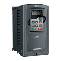
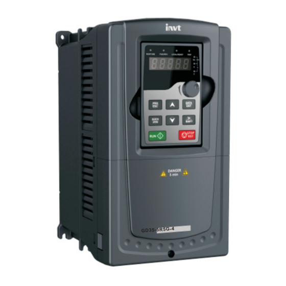
INVT Goodrive35 Series Operation Manual (298 pages)
Closed-loop Vector Control VFD
Brand:
INVT
| Category:
Controller
| Size: 18 MB
Table of Contents
Table of Contents
3
Chapter 1 Safety Precautions
8
What this Chapter Contains
8
Safety Definition
8
Warning Symbols
8
Safety Guidelines
9
Delivery and Installation
9
Commission and Running
10
Maintenance and Replacement of Components
11
Scrap Treatment
11
Chapter 2 Quick Start-Up
12
What this Chapter Contains
12
Unpacking Inspection
12
Application Confirmation
12
Environment
12
Installation Confirmation
13
Basic Commission
13
Chapter 3 Product Overview
14
What this Chapter Contains
14
Basic Principles
14
Product Specification
15
Product Nameplate
17
Model Code
18
Rated Values
18
Rated Value of AC 3PH 380 V (-15%)-440 V (+10%)
18
Rated Value of AC 3PH 520 V (-15%)-690 V (+10%)
19
Structure Diagram
20
Chapter 4 Installation Guide
22
What this Chapter Contains
22
Mechanical Installation
22
Installation Environment
22
Installation Direction
23
Installation Manner
23
Single Installation
24
Multiple Installations
25
Vertical Installation
26
Tilt Installation
27
Standard Wiring
28
Main Circuit Connection Diagram
28
Terminals Figure of Main Circuit
29
Wiring of Terminals in Main Circuit
33
Standard Wiring (Control Circuit)
34
Wiring Diagram of Basic Control Circuit
34
C1 Terminal (EC-PG301-24) Instruction and the Wiring Diagram
37
D1 Terminal (EC-PG304-05) Instruction and the Wiring Diagram
38
H1 Terminal (EC-PG305-12) Instruction and the Wiring Diagram
39
H2 Terminal (EC-PG305-05) Instruction and the Wiring Diagram
40
S1 Terminal (EC-PG302-05) Instruction
42
Input/Output Signal Connection Diagram
43
Wiring Protection
44
Protecting the VFD and Input Power Cable in Short-Circuit Situations
44
Protecting the Motor and Motor Cable in Short-Circuit Situations
45
Protecting the Motor against Thermal Overload
45
Implementing a Bypass Connection
45
Chapter 5 Keypad Operation Procedures
46
What this Chapter Contains
46
Keypad
46
Keypad Displaying
48
Displayed State of Stopping Parameter
48
Displayed State of Running Parameters
48
Displayed State of Fault
49
Displayed State of Function Codes Editing
49
Keypad Operation
49
How to Modify the Function Codes of the VFD
49
How to Set the Password of the VFD
50
How to Watch the VFD State through Function Codes
50
Chapter 6 Function Parameters
52
What this Chapter Contains
52
Goodrive35 General Series Function Parameters
52
Chapter 7 Basic Operation Instruction
142
What this Chapter Contains
142
First Powering on
142
Vector Control
146
SVPWM Control
150
Torque Control
155
Parameters of the Motor
158
Start-Up and Stop Control
163
Frequency Setting
167
Analog Input
171
Analog Output
173
Digital Input
176
Digital Input
184
Simple PLC
188
Multi-Step Speed Running
190
PID Control
192
General Steps of PID Parameters Setting
193
PID Inching
194
Commissioning for Special Functions
196
Commissioning Steps
198
Fault Solutions
204
Chapter 8 Fault Tracking
207
Other States
212
Motor Vibration
213
Undervoltage Fault
214
Abnormal Heating of the Motor
215
Overheat of the VFD
216
Overcurrent
217
Chapter 9 Routine Maintenance
218
Cooling Fan
220
Capacitors
221
Change Electrolytic Capacitors
222
Chapter 10 Communication Protocol
223
RTU Mode
226
RTU Command Code and Communication Data Illustration
229
Command Code: 06H, Writing a Word
231
Command Code: 10H, Continuous Writing
232
The Definition of Data Address
233
Fieldbus Ratio Values
237
Fault Message Response
238
Example of Writing and Reading
240
Common Communication Fault
244
Appendix A Extension Card
245
A.2.2 EC-TX-103 Communication Card
246
A.2.4 Compatible Motor of EC-TX-103 Communication Card
247
A.2.7 System Configuration
251
A.2.8 PROFIBUS-DP Communication
253
A.2.9 Fault Information
261
A.3 Canopen Optional Cards
262
Appendix B Technical Data
263
B.3 Grid Specifications
264
B.5 Applicable Standards
265
B.6.1 Category C2
266
Appendix C Dimension Drawings
267
C.3 VFD Structure
268
C.4 Dimensions for Vfds of AC 3PH 380 V (-15%)–440 V (+10%)
269
C.4.2 Flange Installation
271
C.4.3 Floor Installation
272
C.5 Dimensions for Vfds of AC 3PH 520 V (-15%)–690 V (+10%)
273
C.5.2 Flange Installation
274
C.5.3 Floor Installation
275
Appendix D Optional Peripheral Accessories
277
D.3 Power Supply
279
D.4.2 Control Cables
280
D.4.3 Routing the Cables
283
D.4.4 Insulation Checking
284
D.5.2 Ac 3Ph 520 V (-15%)–690 V (+10%)
285
D.6 Reactors
286
D.6.1 Reactors for AC 3PH 380 V (-15%)–440 V (+10%)
287
D.6.2 Reactors for AC 3PH 520 V (-15%)–690 V (+10%)
288
D.7.1 Filter Model Instruction
289
D.7.2 Filters for AC 3PH 380 V (-15%)–440 V (+10%)
290
D.7.3 Filters for AC 3PH 520 V (-15%)–690 V (+10%)
291
D.8.2 Selecting the Brake Resistor Cables
295
Appendix E Further Information
297
Advertisement
Advertisement
Related Products
INVT Goodrive350 Series
INVT Goodrive350-19 Series
INVT Goodrive350 IP55
INVT Goodrive350-UL Series
INVT Goodrive350A Series
INVT Goodrive300-01A Series
INVT Goodrive3000 GD3000-11-800G-12
INVT Goodrive3000 GD3000-11-630G-12
INVT Goodrive3000 GD3000-11-315G-12
INVT Goodrive3000 GD3000-11-160G-12
INVT Categories
Inverter
DC Drives
Servo Drives
Controller
UPS
More INVT Manuals
Login
Sign In
OR
Sign in with Facebook
Sign in with Google
Upload manual
Upload from disk
Upload from URL