Sign In
Upload
Manuals
Brands
INVT Manuals
Media Converter
Goodrive350 IP55
INVT Goodrive350 IP55 Manuals
Manuals and User Guides for INVT Goodrive350 IP55. We have
1
INVT Goodrive350 IP55 manual available for free PDF download: Operation Manual
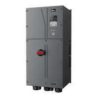
INVT Goodrive350 IP55 Operation Manual (372 pages)
High-ingress Protection Series VFD
Brand:
INVT
| Category:
Media Converter
| Size: 13 MB
Table of Contents
Table of Contents
4
Safety Precautions
10
What this Chapter Contains
10
Safety Definition
10
Warning Symbols
10
Safety Guidelines
11
Delivery and Installation
11
Commissioning and Running
12
Maintenance and Component Replacement
12
Scrap Treatment
13
Precautions for Quick Application
14
What this Chapter Contains
14
Unpack Inspection
14
Application Confirmation
14
Environment Confirmation
14
Installation Confirmation
15
Basic Commissioning
15
Safety Standard Related Data
16
Product Overview
17
What this Chapter Contains
17
Basic Principle
17
Product Specification
18
Product Nameplate
20
Product Model
20
Rated Values
21
Structure Diagram
22
Installation Guide
23
What this Chapter Contains
23
Mechanical Installation
23
Installation Environment
23
Installation Direction
24
Installation Mode
25
Single-Unit Installation
25
Multiple-Unit Installation
26
Vertical Installation
27
Tilted Installation
28
Standard Wiring of Main Circuit
29
Wiring Diagram of Main Circuit
29
Main Circuit Terminal Diagram
30
Wiring Process of the Main Circuit Terminals
32
Standard Wiring of Control Circuit
33
Wiring Diagram of Basic Control Circuit
33
Input/Output Signal Connection Diagram
35
Wiring Protection
36
Protect the VFD and Input Power Cable in Short-Circuit
36
Protect the Motor and Motor Cable in Short Circuit
36
Protect Motor and Prevent Thermal Overload
36
Bypass Connection
37
Basic Operation Instructions
38
What this Chapter Contains
38
Keypad Introduction
38
Keypad Display
41
Displaying Stopped-State Parameters
41
Displaying Running-State Parameters
42
Displaying Fault Information
42
Operating the VFD through the Keypad
43
Enter/Exit Menu
43
Editing a Parameter List
47
Adding Parameters to the Parameter List Displayed in Stopped/Running State
48
Adding Parameters to the User Defined Parameter List
49
Editing User Defined Parameters
49
Editing Parameters in Parameter Groups
50
Monitoring States
51
Autotuning Motor Parameters
51
Backing up Parameters
52
System Settings
52
Power-On Setup Wizard
52
Basic Operation Instruction
53
What this Section Contains
53
Common Commissioning Procedures
54
Vector Control
57
SVPWM Control Mode
62
Torque Control
69
Motor Parameter
73
Start/Stop Control
77
Frequency Setup
83
Analog Input
87
Analog Output
89
Digital Input
93
Digital Output
100
Simple PLC
105
Multi-Step Speed Running
107
PID Control
109
Run at Wobbling Frequency
114
Local Encoder Input
116
Commissioning Procedures for Closed-Loop Control, Position Control and Spindle Positioning
116
Fault Handling
122
Tension Control Solutions
126
Function Parameter List
131
What this Chapter Contains
131
P00--Basic Functions
132
P01--Start/Stop Control
135
P02--Parameters of Motor 1
141
P03--Vector Control of Motor 1
144
P04--V/F Control
150
P05--Input Terminals
157
P06--Output Terminals
164
P07--Hmi
168
P08--Enhanced Functions
174
P09--PID Control
181
P10--Simple PLC and Multi-Step Speed Control
185
P11--Protection Parameters
188
P12--Parameters of Motor 2
195
P13--Control Parameters of Synchronous Motor
198
P14--Serial Communication Function
199
P15--Functions of Communication Expansion Card 1
203
P16--Functions of Communication Expansion Card 2
206
P17--State-Check Functions
210
P18--Closed-Loop Control State Check
214
P19--Expansion Card State Check
217
P20--Encoder of Motor 1
218
P21--Position Control
221
P22--Spindle Positioning
227
P23--Vector Control of Motor 2
229
P24--Encoder of Motor 2
231
P25--Expansion I/O Card Input Functions
234
P26--Output Functions of Expansion I/O Card
237
P27--Programmable Expansion Card Functions
240
P28--Master/Slave Control Functions
242
P90--Tension Control in Speed Mode
245
P91--Tension Control in Torque Mode
248
P92--Tension Optimization
251
P93--Tension Control Status Viewing
252
Troubleshooting
255
What this Chapter Contains
255
Indications of Alarms and Faults
255
Fault Reset
255
Fault History
255
VFD Faults and Solutions
255
Details of Faults and Solutions
255
Other State
264
Analysis on Common Faults
264
Motor Fails to Work
264
Motor Vibrates
265
Overvoltage
266
Undervoltage
266
Unusual Heating of Motor
267
VFD Overheating
268
Motor Stalls During ACC
269
Overcurrent
270
Countermeasures on Common Interference
271
Interference on Meter Switches and Sensors
271
Interference on Communication
272
Failure to Stop and Indicator Shimmering Due to Motor Cable Coupling
273
Leakage Current and Interference on RCD
273
Live Device Chassis
274
Maintenance and Hardware Fault Diagnosis
275
What this Chapter Contains
275
Periodical Inspection
275
Cooling Fan
277
Capacitor
278
Capacitor Reforming
278
Electrolytic Capacitor Replacement
279
Power Cable
279
Communication Protocol
280
What this Chapter Contains
280
Modbus Protocol Introduction
280
Application of Modbus
280
Rs485
280
RTU Mode
283
RTU Command Code and Communication Data
286
Command Code: 03H, Reading N Words
286
Command Code: 06H, Writing a Word
287
Command Code: 08H, Diagnosis
288
Command Code: 10H, Continuous Writing
289
Data Address Definition
289
Fieldbus Scale
293
Error Message Response
294
Read/Write Operation Example
295
Common Communication Faults
300
Appendix A Expansion Cards
301
Model Definition
301
Dimensions and Installation
308
Wiring
311
I/O Expansion Card Function Description
311
IO Expansion Card 1 (EC-IO501-00)
311
IO Expansion Card 2 (EC-IO502-00)
313
Programmable Expansion Card (EC-PC502-00) Function Description
315
Communication Card
318
Bluetooth Communication Card (EC-TX501) and WIFI Communication Card (EC-TX502)
318
PROFIBUS-DP Communication Card (EC-TX503)
320
Ethernet Communication Card (EC-TX504)
321
Canopen Communication Card (EC-TX505) and CAN Master/Slave Control
322
Communication Card (EC-TX511)
322
PROFINET Communication Card (EC- TX509)
323
Ethernet/Ip Communication Card (EC-TX510) and Modbus TCP Communication Card (EC-TX515)
325
PG Expansion Card Function Description
327
Sin/Cos PG Card (EC
327
UVW Incremental PG Card (EC
329
Resolver PG Card (EC
331
Multi-Function Incremental PG Card (EC
333
Incremental PG Card (EC
336
Simplified Incremental PG Card (EC
339
Simplified Incremental PG Card (EC
340
GPRS Card (EC-IC501-2)
344
Appendix B Technical Data
345
What this Chapter Contains
345
Derated Application
345
Capacity
345
Derating
345
Grid Specifications
346
Motor Connection Data
346
EMC Compatibility and Motor Cable Length
346
Application Standards
347
CE Marking
347
EMC Compliance Declaration
347
EMC Regulations
347
VFD Category C2
348
VFD Category C3
348
Appendix C Dimension Drawings
349
What this Chapter Contains
349
VFD Structure
349
Dimensions of Vfds
350
Appendix D Optional Peripheral Accessories
352
What this Chapter Contains
352
Wiring of Peripheral Accessories
352
Power Supply
353
Cables
353
Power Cables
353
Control Cables
354
Cable Arrangement
358
Insulation Inspection
358
Breaker and Electromagnetic Contactor
358
Reactors
359
Filters
360
Filter Model Description
361
Brake System
362
Brake Component Selection
362
Brake Resistor Cable Selection
364
Brake Resistor Installation
364
Appendix E STO Function Description
366
STO Function Logic Table
366
STO Channel Delay Description
366
STO Function Installation Checklist
367
Appendix F Acronyms and Abbreviations
368
Appendix G Energy Efficiency Data
369
Appendix H Further Information
371
Product and Service Queries
371
Advertisement
Advertisement
Related Products
INVT Goodrive350-UL Series
INVT GD350-0R7G-2-UL
INVT GD350-004G-2-UL
INVT GD350-004G/5R5P-4-UL
INVT GD350-015G/018P-4-UL
INVT GD350-022G/030P-4-UL
INVT GD350-037G/045P-4-UL
INVT GD350-500G-4-UL
INVT GD350-1R5G-6-UL
INVT GD350-2R2G-6-UL
INVT Categories
Inverter
DC Drives
Servo Drives
Controller
I/O Systems
More INVT Manuals
Login
Sign In
OR
Sign in with Facebook
Sign in with Google
Upload manual
Upload from disk
Upload from URL