Sign In
Upload
Manuals
Brands
Intel Manuals
Computer Hardware
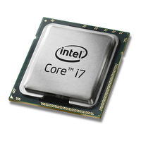
Core i7 Mobile Extreme Edition Series
Intel Core i7 Mobile Extreme Edition Series Manuals
Manuals and User Guides for Intel Core i7 Mobile Extreme Edition Series. We have
1
Intel Core i7 Mobile Extreme Edition Series manual available for free PDF download: Datasheet
INTEL Core i7 Mobile Extreme Edition Series Datasheet (172 pages)
Brand:
INTEL
| Category:
Computer Hardware
| Size: 1 MB
Table of Contents
Table of Contents
3
Revision History
10
1 Introduction
11
2Nd Generation Intel Platform
12
Processor Feature Details
13
Supported Technologies
13
Interfaces
13
System Memory Support
13
PCI Express
14
Pcie Supported Configurations in Mobile Products
14
Direct Media Interface (DMI)
15
Platform Environment Control Interface (PECI)
16
Processor Graphics
16
Embedded Displayport* (Edp*)
17
Intel ® Flexible Display Interface (Intel ® FDI)
17
Power Management Support
17
DMI
17
Memory Controller
17
PCI Express
17
Processor Core
17
System
17
Processor Graphics Controller
18
Thermal Management Support
18
Package
18
Terminology
18
Related Documents
21
2 Interfaces
23
System Memory Interface
23
System Memory Technology Supported
23
Supported SO-DIMM Module Configurations 1,2
23
System Memory Timing Support
24
System Memory Organization Modes
24
Dual-Channel Mode - Intel ® Flex Memory Technology Mode
24
Single-Channel Mode
24
DDR3 System Memory Timing Support
24
Rules for Populating Memory Slots
25
Intel ® Flex Memory Technology Operation
25
Fma)
26
Just-In-Time Command Scheduling
26
Command Overlap
26
Out-Of-Order Scheduling
26
Memory Type Range Registers (Mtrrs) Enhancement
26
Data Scrambling
26
DRAM Clock Generation
26
PCI Express* Interface
27
PCI Express* Architecture
27
PCI Express* Layering Diagram
27
Transaction Layer
28
Data Link Layer
28
Physical Layer
28
Packet Flow through the Layers
28
PCI Express* Configuration Mechanism
29
PCI Express Graphics
29
PCI Express* Related Register Structures in the Processor
29
PCI Express Lanes Connection
30
Direct Media Interface (DMI)
30
DMI Error Flow
30
Processor/Pch Compatibility Assumptions
30
Pcie Typical Operation 16 Lanes Mapping
30
DMI Link down
31
Processor Graphics Controller (GT)
31
Processor Graphics Controller Unit Block Diagram
31
3D and Video Engines for Graphics Processing
32
3D Engine Execution Units
32
3D Pipeline
32
Engine
33
Video Engine
33
Display Planes
34
Processor Graphics Display
34
Processor Display Block Diagram
34
Display Pipes
35
Display Ports
35
Embedded Displayport (Edp)
35
Intel Flexible Display Interface
35
Multi-Graphics Controller Multi-Monitor Support
36
Platform Environment Control Interface (PECI)
36
Interface Clocking
36
Internal Clocking Requirements
36
Reference Clock
36
3 Technologies
37
Intel Virtualization Technology
37
Intel VT-X Objectives
37
Intel VT-X Features
38
Intel VT-D Objectives
38
Intel VT-D Features
39
Intel
39
Intel Trusted Execution Technology (Intel TXT)
40
Intel Hyper-Threading Technology
40
Intel Turbo Boost Technology
41
Intel Turbo Boost Technology Frequency
41
Intel Advanced Vector Extensions (AVX)
42
Intel Turbo Boost Technology Graphics Frequency
42
Advanced Encryption Standard New Instructions (AES-NI)
42
PCLMULQDQ Instruction
43
Intel ® 64 Architecture X2Apic
43
4 Power Management
45
ACPI States Supported
45
System States
45
Processor Core/Package Idle States
45
Processor Core/Package State Support
45
Integrated Memory Controller States
46
Pcie Link States
46
DMI States
46
Processor Graphics Controller States
46
Interface State Combinations
47
G, S, and C State Combinations
47
D, S, and C State Combination
47
Processor Core Power Management
48
Enhanced Intel ® Speedstep ® Technology
48
Low-Power Idle States
48
Idle Power Management Breakdown of the Processor Cores
49
Thread and Core C-State Entry and Exit
49
Requesting Low-Power Idle States
50
Coordination of Thread Power States at the Core Level
50
P_Lvlx to MWAIT Conversion
50
Core C-States
51
Core C0 State
51
Core C1/C1E State
51
Core C3 State
51
Core C6 State
51
Core C7 State
51
C-State Auto-Demotion
52
Package C-States
52
Package C0
53
Package C-State Entry and Exit
53
Coordination of Core Power States at the Package Level
53
Package C1/C1E
54
Package C3 State
54
Package C6 State
54
Package C7 State
55
Dynamic L3 Cache Sizing
55
IMC Power Management
55
Disabling Unused System Memory Outputs
55
DRAM Power Management and Initialization
56
Conditional Self-Refresh
57
Initialization Role of CKE
57
DRAM I/O Power Management
58
Dynamic Power-Down Operation
58
Pcie* Power Management
58
DMI Power Management
58
Targeted Memory State Conditions
58
Graphics Power Management
59
Graphics Performance Modulation Technology(GPMT)
59
Graphics Render C-State
59
Intel
59
Intel Smart 2D Display Technology (Intel S2DDT)
59
Automatic Display Brightness (ADB)
60
Display Power Savings Technology 6.0 (DPST)
60
Intel Graphics Dynamic Frequency
60
Seamless Display Refresh Rate Switching Technology (SDRRST)
61
Thermal Power Management
61
5 Thermal Management
63
Thermal Design Power (TDP) and Junction Temperature (Tj)
63
Thermal Considerations
63
Intel ® Turbo Boost Technology Power Control and Reporting
64
Package Power Control
65
Power Plane Control
65
Turbo Time Parameter
65
Thermal and Power Specifications
66
TDP Specifications
67
Junction Temperature Specification
67
Package Turbo Parameters
68
Idle Power Specifications
69
Thermal Management Features
70
Adaptive Thermal Monitor
70
Processor Package Thermal Features
70
Frequency and Voltage Ordering
71
Digital Thermal Sensor
72
PROCHOT# Signal
73
Processor Core Specific Thermal Features
75
On-Demand Mode
75
Fan Speed Control with Digital Thermal Sensor
76
Memory Controller Specific Thermal Features
76
Platform Environment Control Interface (PECI)
76
Programmable Trip Points
76
6 Signal Description
77
Signal Description Buffer Types
77
System Memory Interface
78
Memory Channel a
78
Memory Reference and Compensation
79
Memory Channel B
79
Reset and Miscellaneous Signals
80
PCI Express* Based Interface Signals
80
PCI Express* Graphics Interface Signals
80
Embedded Displayport (Edp)
81
Intel ® Flexible Display Interface Signals
81
DMI
81
Embedded Display Port Signals
81
Intel® Flexible Display Interface
81
DMI - Processor to PCH Serial Interface
81
PLL Signals
82
TAP Signals
82
Error and Thermal Protection
83
Power Sequencing
83
Processor Power Signals
84
Sense Pins
84
Ground and NCTF
85
Future Compatibility
85
Processor Internal Pull Up/Pull down
85
7 Electrical Specifications
87
Power and Ground Pins
87
Decoupling Guidelines
87
Voltage Rail Decoupling
87
PLL Power Supply
87
Voltage Identification (VID)
88
IMVP7 Voltage Identification Definition
89
Reserved or Unused Signals
92
System Agent (SA)
92
CC VID
92
VCCSA_VID Configuration
92
Signal Groups
93
Signal Groups1
93
Test Access Port (TAP) Connection
95
Storage Condition Specifications
95
DC Specifications
96
Storage Condition Ratings
96
Voltage and Current Specifications
97
Processor Core (VCC) Active and Idle Mode DC Voltage and Current Specifications
97
Processor Uncore (VCCIO) Supply DC Voltage and Current Specifications
98
Memory Controller (VDDQ) Supply DC Voltage and Current Specifications
99
System Agent (VCCSA) Supply DC Voltage and Current Specifications
99
Processor PLL (VCCPLL) Supply DC Voltage and Current Specifications
99
Processor Graphics (VAXG) Supply DC Voltage and Current Specifications
100
DDR3 Signal Group DC Specifications
101
Control Sideband and TAP Signal Group DC Specifications
102
PCI Express DC Specifications
102
Platform Environmental Control Interface (PECI) DC Specifications
103
PECI Bus Architecture
103
Edp DC Specifications
103
PECI DC Characteristics
104
Example for PECI Host-Clients Connection
104
PECI DC Electrical Limits
104
Input Device Hysteresis
105
8 Processor Pin and Signal Information
107
Processor Pin as Signments
107
Rpga988B (Socket-G2) Pinmap (Top View, Upper-Left Quadrant)
108
Rpga988B (Socket-G2) Pinmap (Top View, Upper-Right Quadrant)
109
Rpga988B (Socket-G2) Pinmap (Top View, Lower-Left Quadrant)
110
Rpga988B (Socket-G2) Pinmap (Top View, Lower-Right Quadrant)
111
Rpga988B Processor Pin List by Pin Name
112
BGA1224 Ballmap (Top View, Upper-Left Quadrant)
123
BGA1224 Ballmap (Top View, Upper-Right Quadrant)
124
BGA1224 Ballmap (Top View, Lower-Left Quadrant)
125
BGA1224 Ballmap (Top View, Lower-Right Quadrant)
126
BGA1224 Processor Ball List by Ball Name
127
BGA1023 Ballmap (Top View, Upper-Left Quadrant)
142
BGA1023 Ballmap (Top View, Upper-Right Quadrant)
143
BGA1023 Ballmap (Top View, Lower-Left Quadrant)
144
BGA1023 Ballmap (Top View, Lower-Right Quadrant)
145
BGA1023 Processor Ball List by Ball Name
146
Package Mechanical Information
157
Processor Rpga988B 2C (GT2) Mechanical Package (Sheet 1 of 2)
157
Processor Rpga988B 2C (GT2) Mechanical Package (Sheet 2 of 2)
158
Processor Rpga988B 4C (GT2) Mechanical Package (Sheet 1 of 2)
159
Processor Rpga988B 4C (GT2) Mechanical Package (Sheet 2 of 2)
160
Processor BGA1023 2C (GT2) Mechanical Package (Sheet 1 of 2)
161
Processor BGA1023 2C (GT2) Mechanical Package (Sheet 2 of 2)
162
Processor BGA1224 4C (GT2) Mechanical Package (Sheet 1 of 2)
163
Processor BGA1224 4C (GT2) Mechanical Package (Sheet 2 of 2)
164
Processor Rpga988B 2C (GT1) Mechanical Package (Sheet 1 of 2)
165
Processor Rpga988B 2C (GT1) Mechanical Package (Sheet 2 of 2)
166
Processor BGA1023 2C (GT1) Mechanical Package (Sheet 1 of 2)
167
Processor BGA1023 2C (GT1) Mechanical Package (Sheet 2 of 2)
168
9 DDR Data Swizzling
169
DDR Data Swizzling Table - Channel a
170
DDR Data Swizzling Table - Channel B
171
Advertisement
Advertisement
Related Products
INTEL CORE I7-620 UE - DATASHEET ADDENDUM
INTEL I7-900 DESKTOP PROCESSOR - VOLUME 1
Intel Core i7 Extreme Edition
Intel Core i7 Desktop Series
Intel Core i7-2700K
Intel Core i7-2600K
Intel i7-3770
Intel Core i7-880
Intel Core i7-870
Intel Core i7-3820
Intel Categories
Motherboard
Computer Hardware
Server
Server Board
Desktop
More Intel Manuals
Login
Sign In
OR
Sign in with Facebook
Sign in with Google
Upload manual
Upload from disk
Upload from URL