Sign In
Upload
Manuals
Brands
Furuno Manuals
Marine Equipment
FS-1575
Furuno FS-1575 Manuals
Manuals and User Guides for Furuno FS-1575. We have
6
Furuno FS-1575 manuals available for free PDF download: Service Manual, Operator's Manual, Installation Manual, Gmdss Manual
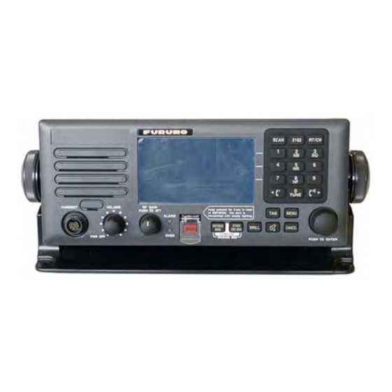
Furuno FS-1575 Service Manual (609 pages)
SSB RADIOTELEPHONE
Brand:
Furuno
| Category:
Radio Modems
| Size: 35.1 MB
Table of Contents
Table of Contents
3
Summary
21
Introduction
21
Optional Operation
22
Software
23
Settings
24
TX Output Power Check and Adjustment
25
Frequency Adjustment
26
Replacement of Boards
27
Checks List
28
Comprehensive Tests
31
Chapter 1. Overview
32
Overview
32
System Configuration
33
FS-2575 and -5075 System Configuration
33
FS-1575 System Configuration
34
Installations
36
Antenna Wiring
36
Key Points to Installation of Antenna
36
Requirements for T/R Antenna
36
Receiving Antenna Wiring Configuration
36
Full-Duplex Communications
37
Selection of Power Supply Cable
38
Positional Data
39
Connection of MAIN FAIL Signal
39
Ext Bk
39
Connection of Handset
39
Operations
40
FS-2575C Control Panel
40
Overview of Display
41
Status Area
41
Tab/Guide Area
42
Information Display Area
42
Overview of RT Window
44
Overview of SCAN Window
44
Overview of DSC Window
45
Transmission of Distress Alert
46
Multi
46
Auto
46
Single
46
Reception of DSC Message
47
Audio Alarms
48
Chapter 2. Parts Location
49
Control Unit: FS-2575C
49
Transceiver Unit: FS-1575T
54
Transceiver Unit: FS-2575T
60
Transceiver Unit FS-5075T
67
Board
74
TX FIL Board: 05P0876 (FS-1575)
74
TX FIL Board: 05P0870B (FS-2575)
75
TX FIL Board: 05P0870A (FS-5075)
76
COMB Board: 05P0869 (FS-5075)
77
PA Board: 05P0868 (FS-1575)
78
PA Board: 05P0867B (FS-2575)
79
PA Board: 05P0867A (FS-5075)
80
DRV Board: 05P0866B (FS-2575)
81
DRV Board: 05P0866A (FS-5075)
82
TX Board: 05P0856 (FS-1575, FS-2575, FS-5075)
83
PA-IF Board: 05P0864 (FS-2575, FS-5075)
84
PA-IF Board: 05P0864A (FS-1575)
85
RX-FIL Board: 05P0862B (FS-1575, FS-2575)
86
RX-FIL Board: 05P0862A (FS-5075)
87
DUP-FIL Board: 05P0863 (FS-5075)
88
RX Board: 05P0842 (FS-1575, FS-2575, FS-5075)
89
WR1 Board: 05P0847A (FS-1575, FS-2575, FS-5075)
90
WR2 Board: 05P0847B (FS-1575, FS-2575, FS-5075)
91
T-IF Board: 05P0861 (FS-2575, FS-5075), 05P0861A (FS-1575)
92
MOT Board: 05P0860 (FS-1575, FS-2575, FS-5075)
93
T-CPU Board: 05P0859 (FS-1575, FS-2575, FS-5075)
94
SW-REG Board: 05P0873 (FS-2575, FS-5075)
95
PWR Board: 05P0874 (FS-1575, FS-2575, FS-5075)
96
P-SW Board: 05P0871 (FS-1575, FS-2575, FS-5075)
97
FET Board: 05P0872 (FS-5075)
98
Antenna Coupler
99
At-5075
99
At-1575
103
NBDP Terminal
107
Term Cpu (16P0209A)
111
PWR Board (16P0211A)
112
SW Board (16P0212)
112
Handset: Hs
118
AC/DC Power Supply Unit
119
Pr-850A
119
Chapter 3. Menu Tree
122
Entering Service Menu
122
Menu Tree
123
Chapter 4. System Setting
137
Introduction
137
Menus
137
Special Operation
138
MMSI Setting and CLEAR All
139
MMSI Setting
139
Mmsi Clear
140
Clear All
140
User Ch
141
Overview
141
USER CH Window Operation
142
Registering USER CH [5]: ENTRY
142
Displaying a LIST of USER CH Registered [6]: LIST
144
Deleting USER CH Registered [4]: DELETE
144
Editing USER CH Registered
145
Searching USER CH Registered [7]: BAND
145
Reflecting Channel Selected on the RT Window [8]: RT SET
145
System
146
Sq Freq]
147
Default: 1000
147
Key Assign]
148
Print]
149
Position]
152
Date/Time]
154
Time Out]
155
Rx Setup]
157
Fax Rx (Disable, Enable)
157
Ant Select (Rx Ant, Trx Ant)
158
Clarifier (On, Off)
159
External Alarm]
160
Network]
162
Dsc
163
Address Book]
164
Registering an Address [5]: ENTRY
165
Displaying a List of Addresses Registered [6]: LIST
166
Deleting Address(S) Registered [4]: DELETE
167
Editing Address Registered [ENTER]: EDIT
167
Reflecting Selected Address on DSC COMPOSE MESSAGE Window
168
[Dsc Msg]: Compose
168
Msg File]
169
Registering a DSC Message [5]: ENTRY
170
Displaying a LIST of DSC Messages Registered [6]: LIST
171
Deleting DSC Message(S) Registered [4]: DELETE
171
Editing DSC Message Registered [ENTER]: DETAIL
172
Reflecting Selected Message File on DSC COMPOSE MESSAGE Window [DSC MSG]: COMPOSE
172
Ack Settings]
173
Special Msg]
175
Routine Scan]
176
Distress Scan]
177
Audio
179
Key Click]
180
Off Hook Sp]
180
Ordinary Alarm]
181
Alarm Distance]
182
Side Tone]
184
Side Tone Lv]
184
Alarm
184
Service
185
Equip Type
186
Dsc Setup
186
Mmsi
186
Sig Detect S- Level (0 - 100) : 80
186
Distress Alarm (0 - 31)
188
Class (Mf, Mf/Hf, Non-Gmdss)
189
Dsc/Dse Sentence (On, Off)
195
Last Distress Log
196
Rt Setup]
197
Tx Freq (All Free, Free, Marine/User, Itu/User, User)
197
Am Mode (Rx Only, Tx/Rx)
201
Cw (Enable, Disable)
202
Lsb
202
Selcall (Enable, Disable)
203
Ref Osc (-127~+127): 0
204
CLARIFIER LIMIT (50Hz~990Hz): +200Hz
204
Tx Tune (On, Off)
205
Coupler through (Off, Rcvd, Diff)
206
Rx Ant (Connect, Disconnect)
207
Divider
215
Line in (-10/+10) 0
215
Line out (-10/+10) 0
215
Format (Iec+Nmea, Iec)
215
Mif (Rs-232C, Rs-485)
216
Restore Factory Settings]
218
Test]
218
Maintenance Log]
218
Other]
219
Pa (On, Off)
219
Alarm Unit (Connect, Disconnect)
219
P-Browser
222
Software Erase
222
Debug Mode (On, Off)
222
Mounting of WR2 Board
223
In Case of FAX-5+2.5M Antenna
223
To Share with T/R ANT
224
To Share with RX ANT (for DUPLEX Communication)
225
WR1 and WR2 Board Jumper Setting
226
EXTERNAL ALM Output Setting (N.C, N.O)
227
Mounting of DUP FIL Board
228
AT-1575 Setting
232
Setting
233
List of Setting Menus
233
Making Setting of Submenu
234
Making Setting of "F5: Station" Menu
234
Making Setting of "F6: System" Menu
237
Making Printer and Language Setting
239
Switching between English and Russian Modes
239
Making Brightness Setting
240
Special Operation
240
Tone Test
240
Checking Detailed Software Version
241
List of IB-583 Menus
242
Setting
243
List of Setting Menus
243
Making Setting of Submenu
244
Making Setting of "F5: Station" Menu
244
Making Setting of "F6: System" Menu
247
Switching between English and Russian Modes
250
F11]: Setup Menu
250
Making Brightness Setting
252
Removing SD Card
252
Special Operation
253
Tone Test
253
Checking Detailed Software Version
254
List of IB-585 Menus
255
AC/DC Power Unit Setting
256
Pr-850A
256
Chapter 5. Adjustment and Measurement
258
Overview of Output Power Adjustment
258
Overview
258
Output Power Characteristics
261
FS-5075: Power Data Vs. RT Output Power
261
FS-5075: RT Output Power Vs. PA IC
262
FS-2575: Power Data Vs. RT Output Power
263
FS-2575: RT Output Power Vs. PA IC
264
FS-1575: Power Data Vs RT Output Power
265
FS-1575: RT Output Power Vs PA IC
266
FS-2575: RT Output Power Vs. MIC INPUT
267
SSB Power Measurement
268
Output Power Measurement by 2-Tone Signal
268
Output Power Measurement by 1-Tone Signal
269
T/R Unit Output Power Adjustment and Measurement
271
Preparation
271
Connection
271
Preparation for Measurement
271
Tx Pwr (Freq)
272
Tx Pwr (User Ch)
274
Tx Pwr (Tune)
277
Tx Pwr (Sel Call)
278
ATU Output Power
280
Connecting Dummy Load to ATU
280
Connecting Antenna to ATU
281
Power Measurement by Calculating Efficiency
282
Frequency Measurement and Adjustment
283
Transmission Frequency Measurement
283
Connection Point of Frequency Counter
283
Frequency Measurement Procedure
284
Frequency Adjustment
286
Dsc Test
288
Tone Test
289
Board Adjustment
290
PA Board Adjustment (FS-1575, -2575, and -5075)
290
PA Board: PA Transistor BIAS Adjustment (FS-1575, -2575, -5075)
292
PA Board: PA VC Check Meter Reading Adjustment
293
PA Board: PA IC Reading Adjustment (FS-1575, -2575, -5075)
294
PA Board: DRIV Transistor Q2-Q3 BIAS Adjustment (FS-1575)
296
PA Board: PRE-DRIV Transistor Q1 BIAS Adjustment (FS-1575)
296
DRV Board Adjustment (FS-2575, -5075)
297
DRV Board: PA Transistor (Q4-Q5) BIAS Adjustment (FS-2575, -5075)
298
DRV Board: PRE-DRV Transistor (Q1) BIAS Adjustment
302
TX Board Adjustment: 05P0856 (FS-1575, -2575, -5075)
303
Mhz REF OSC Frequency Offset Adjustment: R143
303
TX GAIN Adjustment: R208
304
TX FIL Board Adjustment
307
PA-IF Board Adjustment
310
COUP: 05P0875 (FS-2575 and FS-5075)
311
Reception Testing
312
Reception Gain and S/N Ratio Measuring
312
J3E Reception Gain Measuring
312
J3E S/N 20Db Measuring
312
J3E AGC Measuring
312
Measurement Circuits
313
When Not Passing Signal through DIVIDER Circuit on RX FIL Board
313
When Passing Signal through DIVIDER Circuit on RX FIL Board
314
Reception Specifications
315
Chapter 6. Maintenance
316
Menu] -> Test
316
Daily Test
317
Dsc
318
Wr1
318
Wr2
319
Alarm Unit: IC
320
Tx Self Test
321
Codec
322
Tx Pll
324
DRV (FS-2575 and FS-5075)
326
SW-REG 1 and SW-REG 2 (FS-2575 and FS-5075)
326
PA (FS-1575, FS-2575, and FS-5075)
327
Comb (Fs-5075)
328
TX FIL (FS-1575, FS-2575, and FS-5075)
329
COUPLER (FS-1575, FS-2575, and FS-5075)
329
Service: Self Check
330
Vs [V]
332
Tx if in
332
Tx Rf out
332
Drv Vf
332
Drv Vr
332
Drv Temp
332
Unbalance
333
VC [V]
333
IC [A]
333
Pa-Vf
333
Pa-Vr
333
Pa-Temp
333
Filter Vr
334
Filter Alc
334
Alarm
335
Service: Restore Factory Settings
336
Types of Memory Clear Menus
336
Clear Procedure
337
Restore Factory Settings
337
Clear All
337
Mmsi Clear
337
Service: Test
338
Version
338
Verifying Program Version
338
Verifying Board Version
342
Verification of Model: Board INST Signal
343
T-CPU PCB Test
346
Soft, Cpld, Boot
346
Ram, Rom
346
T-CPU, MOT, through DRV
346
C-CPU PCB Test
347
Program Version]
347
Test]: Rom, Ram
347
Test]: Nbdp
348
Pcb Version]
348
Back Led
349
Alarm Led (Red)
349
Other Leds
349
Printer Status
349
Encoder Knob
350
Volume Knob
350
Rf Gain Knob
350
Hook
350
Ptt
350
KEY Mark
350
Lcd Test
351
Ta Test
352
Ac Fail
353
Cw Key
353
Rx Mute
353
Alarm Ack
353
Ext Ptt
353
Continuous Print
353
Distress Scan
354
Popup Alarm
354
MIC Loop Back
354
Iec-61162
354
Alarm Unit
354
Remote
355
Display Test
355
Distress Key Led
355
Alarm Led (Red)
355
Alarm Led (Yellow)
355
Panel Key Led
356
Display Lcd
356
Lcd Current Adj
356
3]: Next
356
Maintenance Log
357
I/O Monitor
357
Iec-61162
357
Alarm Unit
357
Remote
357
Error Log
358
Software Update Log
359
Power on Log
360
Information Log
361
Erasing FS-2575C Software
362
LED Check
365
Leds for FS-Xx75T Unit
365
T-Cpu Board (05P)
365
MOT Board (05P0860)
366
Leds for FS-Xx75C Unit
367
Leds for NBDP Terminal
368
Checking Antenna Coupler
369
Self-Test
369
Checking for Matching Circuit Relays
370
Checking ROM
370
Checking RAM
370
Checking ADC
370
Checking Antenna Coupler
371
Checking for Running of CPU
371
Checking Self-Test
371
Ensuring Finish of Cables and Mounting of Components
371
Ensuring Connection of Coaxial Cable
372
Ensuring Mounting of Copper Grounding Band and Fastening of Gland
372
Ensuring Antenna Connection
373
Troubleshooting for TUNE NG
374
Replacement of Boards
375
List of Boards
375
Precautions for Replacing Board
376
Replacing T-CPU Board
376
Replacing MOT Board
378
Replacing C-CPU Board
379
Replacing C-IF Board
379
Replacing Speaker
380
Applying a Coating of Silicones Compound
381
Actions to be Taken after Replacing Boards
384
WR1 / WR2 Boards: 05P0847A / 05P0847B
384
TX Board: 05P0856 (FS-1575, -2575, -5075)
384
DRV Board: 05P0866A, 05P0866B (FS-5075, -2575)
385
PA Board: 05P0866A, 05P0866B, 05P0868 (FS-5075, -2575, -1575)
385
TX FIL Board: 05P0870A, 05P0870B, 05P0876
385
COMB Board: 05P0869 (FS-5075)
385
PA-IF Board: 05P0864, 05P0864A (FS-5075/-2575, -1575)
385
RX Board: 05P0842 (FS-5075, -2575, -1575)
385
DUP-FIL Board: 05P0863 (FS-5075)
385
RX FIL Board: 05P0862A, 05P0862B (FS-5075, -2575/-1575)
386
MOT Board: 05P0860 (FS-5075, -2575, -1575)
386
T-CPU Board: 05P0859 (FS-5075, -2575, -1575)
386
T-IF Board: 05P0861, 05P0861A (FS-5075/-2575, -1575)
387
C-CPU Board: 05P0852
387
PANEL Board: 05P0844
388
C-IF Board: 05P0853
388
FET Board: 05P0872
388
P-SW Board: 05P0871
388
PWR Board: 05P0874
388
SW REG Board: 05P0873
388
COUP Board: 05P0875 (AT-5075), 05P0883 (AT-1575)
388
Level Check
389
TX Board: 05P0856
389
DRV Board: 05P0866A, B (FS-5075, -2575)
390
PA Board: 05P0867A, B (FS-2575, -5075)
393
PA Board: 05P0868 (FS-1575)
396
COMB Board: 05P0869 (FS-5075)
398
TX FIL Board: (FS-1575, -2575, -5075)
399
Chapter 7. Block Description
401
System Configuration
401
Unit Configuration
401
Configuration of FS-5075T
402
Configuration of FS-2575T
403
Configuration of FS-1575T
404
Configuration of FS-2575C
405
Major Functions of Boards
406
Transceiver Unit: FS-Xx75T
406
Control Unit: FS-2575C
408
Antenna Coupler
408
Transmission Circuit
409
TX Board (05P0856): Common Board
409
Khz TX if Signal
410
Mhz VCTCXO
411
Synthesizer Circuit
411
TX Output Power Control Circuit
412
TX Board Self-Test Detection Circuit
418
DRV Board
419
Protection Circuit
421
IMD Improvement
421
Bias Adjustment
421
PA Board-1
422
Bias Adjustment
424
VC Reading Adjustment
424
IC Reading Adjustment
424
Temp Pa
424
Protection Circuit
426
IMD Improvement
427
Bias Adjustment
427
VC Reading Adjustment
427
IC Reading Adjustment
427
COMB Board (05P0869): FS-5075T
428
TX FIL Board
429
LPF Circuit
430
K17: 50-Ohm BK Relay Circuit
431
R44: 50-Ohm Dummy Load Circuit
431
SWR Detection Circuit
431
PA-IF Board
433
VS Detection
435
Verification of Model
435
PROTECT Signal (FS-2575 and FS-5075)
436
Receiver Circuit
437
RX FIL Board
437
Receiving Filters of RX FIL Board
438
Pre-Selector
439
Rx DIV
440
DUP FIL Board (05P0836): FS-5075
442
RX Board (05P0842): Common Board
445
Khz if RX Signal
446
If Agc
447
Rx Att
447
PLL Synthesizer Circuit
448
RX Board Self-Test Detection Circuit
448
WR Board
450
Differences between WR1 and WR2 Boards
451
If Wr
452
If Agc
452
PLL Synthesizer Circuit
453
WR Board Self-Test Detection Circuit
453
Power Supply for Pre-Amplifier
453
Interface
454
T-IF Board
454
MOT Board (05P0860) for Shared Use
455
T-Cpu
457
Signal Route
457
Overview of Transmitted Voice Signal Route
459
Received Voice Signal Route
459
Transmitted NBDP Signal Route
460
Received NBDP Signal Route
460
Transmitted DSC Signal Route
461
Received DSC (WR1) Signal Route
461
Received DSC (WR2) Signal Route
462
Voice Signal Processing
463
SQ (Squelch)
463
NB (Noise Blanker)
463
NR1 and NR2 (Noise Reduction)
464
NF (Notch Filter)
464
Memory
465
High-Speed Serial Communication
466
Power Supply
467
Power Supply Specifications
467
POWER (05P0874): Common
467
P-SW (05P0871): Common
467
SW REG (05P0873): FS-2575 and FS-5075
467
Power Supply Circuit Diagram
468
Fs-5075 Power Supply Circuit Diagram
468
FS-2575 Power Supply Circuit Diagram
469
FS-1575 Power Supply Circuit Diagram
469
Control Unit: FS-2575C
470
C-CPU Board: 05P0852
471
C-IF Board: 05P0853
471
PANEL Board: 05P0844
471
Set Items Saved in the Control Unit
471
Antenna Coupler
472
FS-2575 and FS-5075
472
Control Signal Timing
473
Matching Circuit
473
Overview of Matching Procedure
475
Self-Test
476
Monitoring Matching Status
477
Calculation of Matching Circuit
492
Gamma Matching
492
Pi-Matching
494
NBDP Terminal
495
Termcpu (16P0283A)
495
Termpwr (16P0287A)
497
Termcpu (16P0209A)
499
Pwr (16P0211A)
500
Chapter 8. Updating Program
501
FS-Xx75 Updating Program
501
Summary for Update
501
List of Program Files
502
Verifying Program Version
503
Program Updating Procedure
505
When Program Version Is Different between T-CPU and C-CPU
512
NBDP Terminal Updating Program
513
Updating Program
513
Verifying IB-583 Program Version
513
Updating Program
514
Updating Program
516
Verifying IB-585 Program Version
516
Updating Program
517
Additional Information: Updating Program Via Serial Port
521
Chapter 9. Q&A
524
Q1. Required Antenna
524
Q2. How to Verify Software Version
524
Q4. Do I Need to Take any Measures When Program Is Updated
524
Q6. When Initiating a Program Update, an Error Message Saying
524
Communication Error!" Is Displayed
524
Q7. Can I Use any Control Unit
524
Q8. How to Register MMSI
524
Q9. How to Enter SERVICE Menu
525
Q10. Is There any Board Available for Use in both the FS-Xx70 and FS-Xx75
525
Q11. I Would Like to Know the Power Supply Specification of PR-850A
525
Q13. I Would Like to Know the Specification of BC-6158
525
Q14. Is the FS-2575 System Available for Duplex Communications
525
Q15. When Turning off the Power, Is the T/R Antenna Grounded
525
Q16. Does the System Support Telegraphy
525
Q17. Can I Operate the System Only with the Radiotelephone Function
525
Q18. Are Alarms Outputted with the Output Contact Set to "N.C" or "N.O
526
Q19. Is It Possible to Turn on the Speaker Even
526
Q20. Is the Parameter Browser of the FS-2570 System Available for Use? Is It Possible to Make MMSI Setting from the Parameter Browser
526
Q21. Is the System Provided with the Main Fail (Power Fail) Function
526
Q23. Is It Possible to Connect a SELCALL (Selective Calling) System
527
Q24. I Would Like to Know the ALC Adjustment Method
527
Q25. I Would Like to Know How to Make Frequency Adjustment
527
Q26. What Is Allowable Deviation of NBDP and DSC Frequencies
527
Up to How Much Deviation Can Messages be Decoded
527
Q27. How to Verify the Model of a System
527
Q28. Using the RX Antenna Resulted in Reduced Receiver Sensitivity
527
What Is the Cause of this Problem
527
Q29. What Do the Figures Shown in Red on the SELF CHECK Window Mean
527
Q30. Which of the GNSS and Manual Modes Is Given Priority to Enter Data
528
Q31. no Positional Data Is Displayed
528
Q32. Can I Change IP Address of System
528
Q33. I Would Like to Know the Sequence to Voice Signal
528
Q34. Is It Possible to Turn on the Power from No. 2 Control Unit
528
Q35. Is There any Method Available to Monitor the Matching Status of ATU
528
Q38. I Would Like to Know Precautions
529
Q39. How Much Collector Current Passes through PA at the Rated Output
529
Q40. TX Output Power Has Dropped Just in 8M
530
Advertisement
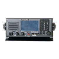
Furuno FS-1575 Operator's Manual (191 pages)
SSB RADIOTELEPHONE
Brand:
Furuno
| Category:
Cordless Telephone
| Size: 23.11 MB
Table of Contents
Important Notices
3
Safety Instructions
4
Table of Contents
9
Foreword
14
System Configurations
16
1 Operational Overview
17
Controls
17
How to Turn On/Off the Power
18
Radiotelephone (RT) Screen
18
DSC Scan Screen
19
How to Adjust the Brilliance of the Display and Panel
20
How to Turn On/Off the Main Speaker
20
How to Scan
20
How to Set the Auto Acknowledgement
21
Control Unit Priority
21
Intercom
22
Operation of Session
22
2 Ssb Radiotelephone
27
How to Select the Class of Emission
27
How to Select the Channel, Frequency
27
Transmission
29
Transmission Procedure
29
How to Change Transmission Power
29
Condition of the Transmitter
30
Reception
31
RF Gain (Sensitivity) Adjustment
31
S-Meter
31
Receive am Broadcasting Stations
31
Noise Blanker
31
Noise Reduction
31
Notch Filter
32
Squelch
32
Attenuator
32
User Channels
32
3 Dsc Overview
33
What Is DSC
33
DSC Message
33
Audio Alarms
34
Description of Call Screens
35
RX Calls
35
TX Calls
36
4 Dsc Distress Operations
37
How to Send Distress Alert
37
How to Send Distress Alert by DISTRESS Key with Distress Information Not Edited
37
How to Send Distress Alert by DISTRESS Key with Distress Information Edited
39
How to Receive a Distress Alert
42
Distress Alert Received on MF Band
42
Distress Alert Received on HF Band
44
How to Send Distress Relay on Behalf of a Ship in Distress
47
How to Send Distress Relay to Coast Station
47
How to Send Distress Relay to Ships in Your Area
48
How to Receive Distress Relay from Coast Station
50
How to Cancel Distress Alert
51
5 Dsc General Message Calling, Receiving
53
Individual Call
53
How to Send an Individual Call
53
How to Receive an Individual Call
58
Group Call
62
How to Send a Group Call
62
How to Receive a Group Call
63
Geographical Area Call
64
How to Send a Geographical Area Call
64
How to Receive a Geographical Area Call
66
Neutral Craft Call
66
How to Send a Neutral Craft Call
66
How to Receive a Neutral Craft Call
68
Medical Transport Call
69
How to Send a Medical Transport Call
69
How to Receive a Medical Transport Call
70
How to Receive a Polling Request
71
Automatic Reply
71
Manual Reply
71
Position Call
72
How to Request Other Ship's Position
72
Other Ship Requests Your Position
74
PSTN Call
75
How to Send a PSTN Call
75
How to Receive a PSTN Call
77
6 Menu Operation
79
How to Open/Close the MENU Screen
79
User Channels
80
List for User Channels
80
How to Register User Channels
80
How to Edit User Channels
81
How to Delete User Channels
82
How to Sort the USER CH List by Band
82
How to Select User Channels for SSB Mode
83
Log File
83
How to Open a Log File
83
How to Delete Log Files
84
Squelch Frequency
85
Key Assignment
85
How to Print Messages
86
Position Setting
86
Date and Time Setting
87
Timeout Setting
88
FAX Enable/Disable
88
How to Select the Antenna
89
Clarifier Setting
89
External Alarm Setting
90
NETWORK Setting
90
Address Book
91
List for Address Data
91
How to Register Addresses
91
How to Edit Addresses
92
How to Delete Addresses
93
How to Create a DSC Message with Registered Address
93
TX Message Preparation
94
List for Message Files
94
Individual Calls
95
Group Calls
96
PSTN Calls
96
Test Call
97
How to Edit Prepared Messages
97
How to Send Prepared Messages
98
How to Delete Prepared Messages
98
How to Set the AUTO ACK Details
99
Special Messages
100
How to Set Scan Frequencies
100
Sound Setting
101
Alarm Lists
102
7 Nbdp System Overview
103
How to Turn on the NBDP System
103
Description of Equipment
103
Terminal Unit
103
Keyboard
105
Encoding Setting
106
Function Keys, Menu Operation
107
Menu Conventions
107
Menu Overview
107
Function Key Description
108
8 Nbdp Preparations
113
Registration of Answerback & ID Codes
113
How to Register Answerback Code
113
How to Register ID Codes
114
User Channels
114
How to Register User Channels
114
How to Edit/Delete User Channels
115
Station List
115
How to Register Stations
115
How to Edit/Delete Stations
117
Timer Programming
117
How to Register Timer Programs
117
How to Edit/Delete Timer Programs
118
Scan Channel Groups
118
How to Register Scan Channel Groups
119
How to Edit/Delete Scan Channel Groups
120
How to Change the Window Color
120
Ib-585
121
Screen Saver Function for IB-585
122
9 Nbdp File Operations
123
How to Open and Close Files
123
How to Create Files
123
How to Save a File
124
How to Format Floppy Disks or SD Cards
125
How to Save a File
125
How to Edit Files
125
How to Cut and Paste Text
125
How to Copy and Paste Text
126
Select All
126
How to Search Text
127
How to Replace Text
127
Goto Line
128
Goto Top, Goto Bottom
128
How to Open Files
128
Open a File
128
Switch between Files
129
How to Rename Files
129
How to Save a File under a New Name
129
How to Delete Files
130
Real Time Printing
130
How to Print Files
130
10 Nbdp Transmission, Reception
131
Manual Calling
131
ARQ Mode Operation
133
FEC Mode Operation
135
How to Select Reception Mode
135
Communication Example
136
Timer Operation
138
How to Enable Timer Operation
138
How to Stop Timer Operation
138
Scanning
139
Communication Buffer
139
Preparation of Macrofiles for Automatic Telex
140
Automatic Telex Overview
140
Preparations
140
Commands
141
Store-And-Forward Method
143
10.10 Automatic Telex Using Macrofile
145
Furuno FS-1575 Installation Manual (88 pages)
SSB
Brand:
Furuno
| Category:
Telephone
| Size: 12.91 MB
Table of Contents
Table of Contents
1
Safety Instructions
3
System Configuration
5
Equipment List
6
Optional Equipment
6
Standard Supply
6
1 How to Install the System
9
Control Unit FS-2575C
9
Installation Location
9
How to Install the Unit on a Desktop
9
How to Install the Unit in a Console (Flush Mount)
10
Antenna Coupler AT-1575, AT-5075
11
General Considerations
11
Indoor Installation
11
Ground
12
Outdoor Installation
12
Installation Procedure
13
Transceiver Unit FS-1575T, FS-2575T, FS-5075T
14
Handset HS-2003
14
Antenna
15
Types of Antennas
15
General Requirements
15
Installation Requirements for Whip Antenna
16
RX Antenna
16
How to Install Optional Equipment
16
Preamp Unit FAX-5
16
Printer Interface IF-8500
17
External Loudspeaker SEM-21Q
17
AC-DC Power Supply PR-850A, PR-300
17
Terminal Unit IB-585
18
How to Install the Terminal Unit
18
How to Install the Keyboard
18
Keyboard for IB-585
18
Automatic Antenna Switch AS-102
19
WR2 Board
20
Watch Receiver Kit (Type: OP05-123, Code No.: 001-135-610)
20
R_ANT and WR2_ANT Antennas Shared
21
Separate R_ANT and WR2_ANT
21
DUP-FIL Board (FS-5075 Only)
22
Waterproofing Kit for the Control Unit
23
How to Protect Unused Connector(S), Speaker Jack
23
Two Connectors
23
One Connector
23
How to Protect Connector, Speaker Jack in Use
24
2 Wiring
25
Fs-1575
25
Fs-2575
26
Fs-5075
27
Antenna Coupler
28
General Connections
28
Antenna Coupler AT-1575, AT-5075, Bottom Front View
28
AT-1575(In the Case of 05P0883-00)
29
Antenna Coupler AT-1575, Inside View (Old Type Board,05P0883-00)
29
AT-1575(In the Case of 05P0883-22)
30
Antenna Coupler AT-1575, Inside View (New Type Board,05P0883-22)
30
At-5075
31
Antenna Coupler AT-5075, Inside View
31
Connections for Outside Installation
33
Transceiver Unit
34
Transceiver Unit FS-1575T, Inside View
34
Power Cable
35
Transceiver Unit FS-5075T, Inside View
35
Coaxial Cable
36
5-Pair Cable
36
Control Unit
37
External Equipment
37
Gnss
37
Fabrication of TTYCS Series
37
Fabrication of TTYCSLA Series
38
EXT BK (SSB Radiotelephone, Etc.)
38
MIF Unit
39
Keyboard for Terminal Unit IB-585
39
How to Process Power Cables
40
How to Select Input Voltage
40
AC-DC Power Supply Unit PR-300/PR-850A (Option)
40
Tap Connections in the PR-300
41
PR-850A for FS-2575/5075
41
Front View
41
Rear View
41
AC FAIL Line (PR-850A)
42
Automatic Antenna Switch AS-102 (Option)
43
How to Process the Cable (Example: DPYCY-1.5)
43
3 Initial Settings
45
How to Initialize the Control Unit and Transceiver Unit
45
How to Enter MMSI
45
Performance Check
46
System Setup
46
SERVICE Menu
46
EQUIP TYPE Menu
46
DSC SETUP Menu
47
RT SETUP Menu
47
Tx Pwr (Freq)
48
Tx Pwr (User Ch)
48
OTHER Menu
49
Example Antenna Configurations
50
Separate Antennas Configurations
50
Shared Antenna Configurations
51
Full Duplex Configurations (FS-5075 Only)
52
Alarm Contact Signal
53
I/O Data
54
Core Type
55
Insulation Type
55
Sheath Type
55
Advertisement
Furuno FS-1575 Installation Manual (87 pages)
SSB RADIOTELEPHONE
Brand:
Furuno
| Category:
Telephone
| Size: 10.22 MB
Table of Contents
Table of Contents
1
Safety Instructions
3
System Configuration
5
Equipment List
6
Optional Equipment
6
1 How to Install the System
9
Control Unit FS-2575C
9
Antenna Coupler AT-1575 (FS-1575), AT-5075 (FS-2575, FS-5075)
11
Installation Procedure
13
Transceiver Unit FS-1575T (FS-1575), FS-2575T (FS-2575), FS-5075T (FS-5075)
14
Handset HS-2003
14
Antenna
15
How to Install Optional Equipment
16
2 Wiring
23
Antenna Coupler
26
Transceiver Unit
30
Control Unit
33
External Equipment
33
AC-DC Power Supply Unit PR-300/PR-850A (Option)
36
Automatic Antenna Switch AS-102 (Option)
39
3 Initial Settings
40
How to Initialize the Control Unit and Transceiver Unit
40
How to Enter MMSI
40
Performance Check
41
System Setup
42
Dsc Setup Menu
43
Rt Setup Menu
44
Other Menu
48
Alarm Contact Signal
52
I/O Data
52
Interconnection Diagram
85
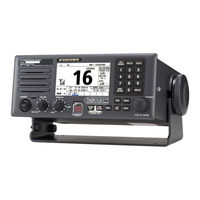
Furuno FS-1575 Gmdss Manual (6 pages)
GMDSS - Global Maritime Distress and Safety System
Brand:
Furuno
| Category:
Marine Equipment
| Size: 3.37 MB
Furuno FS-1575 Operator's Manual (2 pages)
SSB RADIOTELEPHONE
Brand:
Furuno
| Category:
Cordless Telephone
| Size: 0.57 MB
Advertisement
Related Products
Furuno FS-2575
Furuno FS-5075
Furuno FS-75
Furuno FS-2550
Furuno FSV-25 MARK-2
Furuno F-851SD
Furuno FI-309
Furuno FG-11-A Mark-3
Furuno FG-200-A Mark-3
Furuno FELCOM251
Furuno Categories
Marine Radar
Marine Equipment
Sonar
Monitor
GPS
More Furuno Manuals
Login
Sign In
OR
Sign in with Facebook
Sign in with Google
Upload manual
Upload from disk
Upload from URL