Furuno FS-1575 Installation Manual
Ssb
Hide thumbs
Also See for FS-1575:
- Service manual (609 pages) ,
- Operator's manual (191 pages) ,
- Installation manual (87 pages)
Table of Contents
Advertisement
Installation Manual
SSB RADIO TELEPHONE
Fs-1575/FS-2575/FS-5075
Model
Safety Instructions ................................................................................................ i
System Configuration .......................................................................................... iii
Equipment List .......................................................................................................... iv
1. HOW TO INSTALL THE SYSTEM .........................................................................1-1
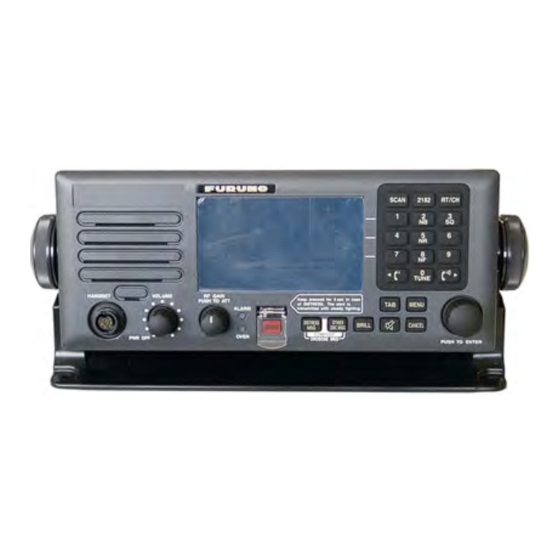
1.1 Control Unit FS-2575C.......................................................................................................1-1
1.2 Antenna Coupler AT-1575, AT-5075 .................................................................................1-3
1.3 Transceiver Unit FS-1575T, FS-2575T, FS-5075T ...........................................................1-6
1.4 Handset HS-2003 ..............................................................................................................1-6
1.5 Antenna..............................................................................................................................1-7
1.6 How to Install Optional Equipment.....................................................................................1-8
2. WIRING....................................................................................................................2-1
2.1 Antenna Coupler ................................................................................................................2-4
2.2 Transceiver Unit...............................................................................................................2-10
2.3 Control Unit ......................................................................................................................2-13
2.4 External Equipment..........................................................................................................2-13
2.5 AC-DC Power Supply Unit PR-300/PR-850A (option) .....................................................2-16
2.6 Automatic Antenna Switch AS-102 (option) ....................................................................2-19
3. INITIAL SETTINGS..................................................................................................3-1
3.1 How to Initialize the Control Unit andTransceiver Unit.......................................................3-1
3.2 How to Enter MMSI............................................................................................................3-1
3.3 Performance Check ...........................................................................................................3-2
3.4 System Setup.....................................................................................................................3-2
3.5 Alarm Contact Signal .........................................................................................................3-9
3.6 I/O Data............................................................................................................................3-10
Appendix 1 Jis Cable Guide .............................................................................AP-1
PACKING LISTS ........................................................................................................ A-1
OUTLINE DRAWINGS ................................................................................................ D-1
INTERCONNECTION DIAGRAMS.............................................................................. S-1
www.furuno.com
All brand and product names are trademarks, registered trademarks or service marks of their respective holders.
Advertisement
Table of Contents

Related Manuals for Furuno FS-1575


Summary of Contents for Furuno FS-1575
- Page 1 Installation Manual SSB RADIO TELEPHONE FS-1575/FS-2575/FS-5075 Model SAFETY INSTRUCTIONS ....................i SYSTEM CONFIGURATION ..................iii EQUIPMENT LIST ......................iv 1. HOW TO INSTALL THE SYSTEM .................1-1 1.1 Control Unit FS-2575C.......................1-1 1.2 Antenna Coupler AT-1575, AT-5075 .................1-3 1.3 Transceiver Unit FS-1575T, FS-2575T, FS-5075T ............1-6 1.4 Handset HS-2003 ......................1-6...
- Page 2 ・FURUNO Authorized Distributor/Dealer 9-52 Ashihara-cho, Nishinomiya, 662-8580, JAPAN A : JUL 2011 Printed in Japan All rights reserved. N : MAY 17, 2017 Pub. No. IME-56770-N ( TEHI ) FS-1575/2575/5075 0 0 0 1 9 2 6 8 9 1 2...
-
Page 3: Safety Instructions
SAFETY INSTRUCTIONS The installer must read the safety instructions before attempting to install the equipment. Indicates a potentially hazardous situation which, if not avoided, DANGER will result in death or serious injury. Indicates a potentially hazardous situation which, if not avoided, WARNING could result in death or serious injury. - Page 4 SAFETY INSTRUCTIONS CAUTION NOTICE Follow the compass safe distances to prevent Confirm that the power supply interference to a magnetic compass. voltage is compatible with the voltage rating of the equipment. Standard Steering Unit Compass Compass Connection to the wrong power supply can cause fire or damage 2.30 m 1.50 m...
-
Page 5: System Configuration
For DSC distress frequency AUTOMATIC ANTENNA watch keeping receiver SWITCH AS-102 2.6 m whip RX antenna antenna ANTENNA COUPLER AT-1575 (FS-1575) or PREAMP PREAMP ANT. JUNC. BOX AJB1-1A or AT-5075 (FS-2575, FS-5075) FAX-5 MATCHING BOX ARD-1 FAX-5 BK INTERFACE... -
Page 6: Optional Equipment
EQUIPMENT LIST Standard Supply Name Type Code No. Remarks FS-1575T For FS-1575 Transceiver FS-2575T For FS-2575 Unit FS-5075T For FS-5075 Control Unit FS-2575C Antenna AT-1575 For FS-1575 Coupler AT-5075 For FS-2575/5075 CP05-12100 000-019-245 For FS-2575C, no cable, with inst. mat. - Page 7 Code No. Remarks FAX-5 *15M* 000-011-702 w/15 m cable Preamp FAX-5 *1M* 000-011-703 w/1 m cable AC-DC Power Sup- PR-300 000-015-941-10 For FS-1575 ply Unit PR-850A 000-057-233 For FS-2575/5075 Matching Box ARD-1 005-502-230 For matching, w/resistor Antenna Junction AJB1-1A 000-870-284...
- Page 8 005-964-410 25 m E-24 000-050-634 Antenna Installation Materials E-25 000-050-635 E-26 000-050-636 E-27 000-050-637 TM-173-D4 L1520Y8 000-176-211-10 For FS-1575 Wire Rope Assy. TM-173-D4 L1670Y8 000-175-179-10 For FS-2575 TM-173-D4 L1800Y8 000-175-178-10 For FS-5075 000-159-411-10 10 m 000-159-412-10 20 m RG-10/U-Y 000-159-413-10...
-
Page 9: How To Install The System
HOW TO INSTALL THE SYSTEM Control Unit FS-2575C 1.1.1 Installation location • The location must not be near water, rain and water splash. • Make sure the location is strong enough to hold the unit under the conditions of con- tinued vibration and shock normally found on the boat. - Page 10 1. HOW TO INSTALL THE SYSTEM 1.1.3 How to install the unit in a console (flush mount) The flush mount kit is required to install the Control Unit in a console. Type: OP05-122, Code No.: 001-135-600 Name Type Code No. Mounting metal 05-089-1171-0 100-299-020...
-
Page 11: Antenna Coupler At-1575, At-5075
1. HOW TO INSTALL THE SYSTEM Antenna Coupler AT-1575, AT-5075 The Antenna Coupler is installed between the antenna and the Transceiver Unit, and tunes the antenna to the transmitter. The coupler must have a correct ground to func- tion properly. The radiotelephone cannot provide its intended performance unless the ground is proper. - Page 12 1. HOW TO INSTALL THE SYSTEM Outdoor installation • The coupler is water-jetsproof, but is not designed to take a continual soaking. • Install the coupler close to the antenna base. • Keep wires as short as possible and keep the wires away from any grounded con- ductors such as lifelines, mast shrouds, or fittings.
-
Page 13: Installation Procedure
1. HOW TO INSTALL THE SYSTEM 1.2.3 Installation procedure Outdoor installation Fasten the Antenna Coupler to a bulkhead of the bridge, mast, handrail, etc., with the M6 bolts (local supply). For installation on the mast, see section 1.5 to select a location. Weld suitable mount- ing fixtures (local supply) to the mast and bolt the coupler there. -
Page 14: Transceiver Unit Fs-1575T, Fs-2575T, Fs-5075T
1. HOW TO INSTALL THE SYSTEM Transceiver Unit FS-1575T, FS-2575T, FS-5075T Select a location that meets these conditions: • Select a location which provides good ventilation. • The location must be clean and dry. • Make sure the location can hold the unit under the conditions of continued vibration and shock normally found on the boat. -
Page 15: Antenna
1. HOW TO INSTALL THE SYSTEM Antenna The antenna plays the most important role in radio communication. If it cannot receive or transmit due to improper installation, even the most sophisticated transceiver will be useless. After setting up the equipment, confirm that the antenna can tune all fre- quencies. -
Page 16: How To Install Optional Equipment
In the COSAR Circ.32, it is recommended that the down lead should be more than 45 degrees towards the horizontal plane. • For indoor installation, use a lead-in insulator (FURUNO type: YA-256) to make the connection. If necessary, use a high quality antenna switch and stand-off insulator. - Page 17 1. HOW TO INSTALL THE SYSTEM 1.6.3 Printer Interface IF-8500 Refer to the outline drawing at the end of this manual for mounting dimensions and recommended maintenance space. Follow the compass safety distance shown in the Safety Instructions to prevent interference to a magnetic compass. Fasten the Printer Interface with self-tapping screws (local supply) to desktop or bulkhead.
- Page 18 1. HOW TO INSTALL THE SYSTEM 1.6.6 Terminal Unit IB-585 Install the Terminal Unit on a desktop. Select a location that meets the following con- ditions. • The temperature and humidity in the location must be stable and moderate. • Keep the unit away from the high-power radiotelephone and its feeder wire so that RFI (Radio Frequency Interference) is minimum.
- Page 19 1. HOW TO INSTALL THE SYSTEM 1.6.7 Automatic Antenna Switch AS-102 The Automatic Antenna Switch AS-102 allows you to connect the antenna to ground remotely with an external switch when there is a possibility of lightning, or the antenna must be grounded to meet with local regulations when returning to a harbor. Install the unit between the antenna and the Antenna Coupler.
- Page 20 1. HOW TO INSTALL THE SYSTEM 1.6.8 WR2 Board The WR2 Board (05P0847B) enables reception of DSC routine frequencies while us- ing the SSB radiotelephone connection. See section 3.4.6 for antenna configurations. Watch Receiver Kit (Type: OP05-123, Code No.: 001-135-610) Name Type Code No.
- Page 21 1. HOW TO INSTALL THE SYSTEM 4. Make the following connections between the WR2 Board / ANT WR2 / RX-FIL Board, with the Mini-pin assy. (supplied with this kit) and the connector assy. (sup- plied with this kit). R_ANT and WR2_ANT antennas shared Separate R_ANT and WR2_ANT Board Board...
- Page 22 1. HOW TO INSTALL THE SYSTEM 1.6.9 DUP-FIL Board (FS-5075 only) The DUP-FIL Board (05P0863) installs above the RX-FIL Board (05P0862A) and gives the FS-5075 full duplex capability. Parts Name: Full Duplex Kit, Type No. OP05- 125, Code No. 001-135-630 Name Type Code No.
- Page 23 1. HOW TO INSTALL THE SYSTEM 1.6.10 Waterproofing kit for the Control Unit The waterproofing kit OP-126 (Code No. 001-148-880) protects the connectors and jacks on the control unit from water ingress, to waterproofing standard IP22. Name Type Code No. DSUB gasket 05-106-5571-1 100-365-871-10...
- Page 24 1. HOW TO INSTALL THE SYSTEM How to protect connector, speaker jack in use CONNECTOR IN USE SPEAKER JACK IN USE 1) Pass the cable through 1) Pass the cable through the DSUB clamping the SPJACK clamping plate. plate. Note the orientation of the SPJACK clamping straight edge on the clamp-...
-
Page 25: Wiring
For detailed information, see the interconnection diagram. Many of the cables men- tioned are JIS (Japan Industry Standard) cables. If not available locally, use the equiv- alent. See the cable guide in the Appendix for how to select equivalent cables. FS-1575 TX/RX ANTENNA or TX ANTENNA... - Page 26 2. WIRING FS-2575 TX/RX ANTENNA or TX ANTENNA PREAMP AUTOMATIC ANTENNA FAX-5 SWITCH AS-102 RX ANTENNA Ground 3D-2V Wire RG-10/U-Y MATCHING BOX ARD-1 or ANT. JUNC. BOX AJB1-1A PRINTER NBDP TERMINAL IB-585 ANTENNA COUPLER 05S9351 INTERFACE IF-8500 AT-5075 or PRINTER Keyboard (IB-585) CONTROL UNIT 5139U or 5139U BLACK...
- Page 27 2. WIRING FS-5075 TX/RX ANTENNA or TX ANTENNA PREAMP AUTOMATIC ANTENNA FAX-5 SWITCH AS-102 RX ANTENNA Ground 3D-2V Wire RG-10/U-Y MATCHING BOX ARD-1 or ANT. JUNC. BOX AJB1-1A PRINTER NBDP TERMINAL IB-585 ANTENNA COUPLER 05S9351 I/F KIT IF-8500 AT-5075 or PRINTER Keyboard (IB-585) CONTROL UNIT 5139U or 5139U BLACK...
-
Page 28: Antenna Coupler
2. WIRING Antenna Coupler Note: The T/R antenna is automatically connected to ground when the power is turned off. 2.1.1 General connections Three cables connect to the Antenna Coupler: the signal cable (7-core cable (05S0952) or 5P cable (05S0793)), coaxial cable from the Transceiver Unit, and the antenna wire. - Page 29 2. WIRING 5. Fabricate the signal cable and the coaxial cable as shown below. * How to process the shield: ** How to fabricate the coaxial cable: Crimp-on Wrap the shield with vinyl tape, 50 mm * fasten crimp-on lug to vinyl wire, fasten crimp-on lug to the 20 mm “E”...
- Page 30 2. WIRING AT-1575(In the case of 05P0883-22) Version of the board Fixing plate Shield COAXIAL CABLE Fixing plate Antenna Coupler AT-1575, inside view (New type board,05P0883-22) a) Connect the wires from the signal cable to TB5, as shown in the diagram below. No.
- Page 31 2. WIRING AT-5075 Locking wire saddle SIGNAL CABLE (See section 2.2.4 for how to fabricate.) Shield Be sure cable does not touch resistors. Fixing Plate COAXIAL CABLE Antenna Coupler AT-5075, inside view a) Pass the signal cable into the transceiver unit, taking care that the cable does not touch the resistors.
- Page 32 2. WIRING 7. Check that the gasket is engaged to the posts on the casing then close the cover. (Pictured: AT-5075) Post...
- Page 33 2. WIRING 2.1.2 Connections for outside installation For outside installation, arrange the antenna wire as shown below. The optional an- tenna materials shown below are necessary. Name Type Code No. Remarks Antenna materials CP05-09010 005-954-180 w/10 m antenna cable CP05-09020 005-964-410 w/25 m antenna cable 1.
-
Page 34: Transceiver Unit
2. WIRING Transceiver Unit 2.2.1 General connections The general procedure for connecting cables to the Transceiver Unit is as follows: 1. Treat the cable end. See section 2.2.4. 2. Use a knife to cut intersecting cuts in the applicable rubber bushing at the bottom of the unit. -
Page 35: Power Cable
Power cable 70 (FS-1575T) Fabricate the cable DPYC-6 150 (FS-2575T, FS-5075T) Armor (Max 10 m, FS-1575), DPYC-10 (Max 10 m, FS- 2575) or DPYC-16 (Max 10 Sheath m, FS-5075) as shown be- low. Attach the crimp-on Set this part in cable clamp. -
Page 36: Coaxial Cable
2. WIRING 2.2.3 Coaxial cable Coaxial cables connect the antennas to the Transceiver Unit. Attach the M-type con- nector of the coaxial cable. Leave some slack in the coaxial cable so that the cover of the Transceiver Unit can be opened easily. The antennas are connected to the Transceiver Unit with a 50 ohm coaxial cable, type RG-10/U-Y, RG-8A/U or 3D-2V. -
Page 37: Control Unit
2. WIRING Control Unit Connect the Transceiver Unit to the Control Unit with the cable with the D-sub 15-pin connector on one end. Connect a single Control Unit to the CONTROLLER 1 port. (This port has priority when two Control Units are connected.) Connect a No.2 Control Unit to the CONTROLLER 2 port. - Page 38 2. WIRING Fabrication of TTYCSLA series Sheath Drain wire Length of “L” FS-1575T FS-2575T/FS-5075T Cover the drain wire with the heat-shrinkable tubing, then attach the crimp-on lug to it. Vinyl tape 8 - 10 Clamp here by cable clamp. EXT BK (SSB radiotelephone, etc.) Terminal no.
- Page 39 2. WIRING MIF unit Use connector 17JE-13250-02 (supplied as installation materials) to connect the MIF unit to the REMOTE port on Transceiver Unit. Shield tape (metal) Fold back armor, then wind shield tape along edge of cable. Cable clamp Cable Type: UL2464-SM (M) 13PX28AWG...
-
Page 40: Ac-Dc Power Supply Unit Pr-300/Pr-850A (Option)
To connect to both an AC and DC ship’s mains, the optional AC-DC power supply unit PR-300 (FS-1575) or PR-850A (FS-2575/FS/5075) is required. Attach the crimp on lug FV5.5-4 (local supply) to the following cables or equivalent (local supply) for con- nection with the power supply unit. - Page 41 2. WIRING 100V 110V 100 (FAN) 100 (FAN) 100 VAC SHIP’S MAINS 110 VAC SHIP’S MAINS 200V 220V 100 (FAN) 100 (FAN) 220 VAC SHIP’S MAINS 200 VAC SHIP’S MAINS Tap connections in the PR-300 PR-850A for FS-2575/5075: The input voltage is adjustable for 100/110/120/200/220/240 VAC, and is factory-set for 220 VAC.
- Page 42 2. WIRING For 100 VAC Input For 110 VAC Input For 200 VAC Input For 120 VAC Input (Standard) For 220 VAC Input For 240 VAC Input AC FAIL line (PR-850A) When the power supply is PR-850A FS-2575T/5075T switched to the back-up, AC T-IF Board and FAIL at PR-850A are (05P0861)
-
Page 43: Automatic Antenna Switch As-102 (Option)
2. WIRING Automatic Antenna Switch AS-102 (option) The Automatic Antenna Switch AS-102 allows you to connect the antenna to ground remotely with an external switch when there is a possibility of lightning, or the antenna must be grounded to meet with local regulations when returning to a harbor. Install the unit between the antenna and the Antenna Coupler. - Page 44 2. WIRING This page is intentionally left blank. 2-20...
-
Page 45: Initial Settings
INITIAL SETTINGS This chapter shows you how to enter the initial settings. A password is required to en- ter the initial settings. Refer to FURUNO Information for the password. How to Initialize the Control Unit and Transceiver Unit Turn on the power switch on the Control Unit. The equipment starts to update the soft- ware, in the sequence shown below. -
Page 46: Performance Check
3.4.1 SERVICE menu A password is required to access the [SERVICE] menu. For details of the [SERVICE] menu, see the service manual of the FS-1575/2575/5075. Use the default setting. 3.4.2 EQUIP TYPE menu The system automatically detects the model name and displays the results, [FS-... - Page 47 3. INITIAL SETTINGS 3.4.3 DSC SETUP menu The [DSC SETUP] menu sets up the system’s DSC features. MMSI: Ship’s MMSI (display only). CLASS: Set the function of the watch receiver: [MF/HF] (sea area A3), [MF] (sea area A1, A2), or [NON-GMDSS] (DSC function disabled). 3.4.4 RT SETUP menu SETUP...
- Page 48 TX POWER ADJ: Set the TX power. TX TONE: Output tone. LOAD DEFAULT: Restore default TX power (frequency) settings. For details of the settings on the [TX POWER (FREQ)] menu, see the service manual of FS-1575/2575/5075. TX PWR (USER CH) xx.xA x.xA* PA1 current xx.xA...
- Page 49 TX POWER ADJ: Set the TX power. TX TONE: Output tone. LOAD DEFAULT: Restore default TX power (user channel) settings. For details of the settings on the [TX POWER (USER CH)] menu, see the service manual of FS-1575/2575/5075. 3.4.5 OTHER menu P-BROWSER : Select [ON] to enable the parameter browser, controlled from a PC.
- Page 50 3. INITIAL SETTINGS 3.4.6 Example antenna configurations Separate Antennas Configurations Separate antennas configuration 1: Separate R_ANT and WR1 antennas 1) Set [RX ANT] on the [RT SETUP] menu to [CONNECT]. 2) Set [ANT SELECT] on the [RT SETUP] menu to [RX ANT] or [TRX ANT]. 3) Turn off [DIVIDER] in the [RT SETUP] menu of the [SERVICE] menu.
- Page 51 3. INITIAL SETTINGS Shared antenna configurations Shared antenna configuration 1: R_ANT and WR1 antennas commonly shared 1) Set [RX ANT] on the [RT SETUP] menu in the [SERVICE] menu to [CONNECT]. 2) Turn on [DIVIDER] in the [RT SETUP] menu of the [SERVICE] menu. 3) Use the mini-pin assemblies (supplied) to make these connections: •...
- Page 52 3. INITIAL SETTINGS Full duplex configurations (FS-5075 only) Full duplex configuration 1: Separate R_ANT and WR1 antennas, optional DUP- FIL board installed Watch on DSC general frequencies available with installation of optional WR2 Board. 1) Set [RX ANT] on the [RT SETUP] menu to [CONNECT]. 2) Set [ANT SELECT] on the [RT SETUP] menu to [RX ANT].
-
Page 53: Alarm Contact Signal
3. INITIAL SETTINGS Full duplex configuration 2: R_ANT and WR2 antennas commonly shared 1) Set [RX ANT] on the [RT SETUP] menu to [CONNECT]. 2) Set [ANT SELECT] on the [RT SETUP] menu to [RX ANT]. 3) Turn on [DIVIDER] in the [RT SETUP] menu of the [SERVICE] menu. R_ANT T/R_ANT T/R_ANT... -
Page 54: I/O Data
3. INITIAL SETTINGS I/O Data Data Input/Output Sentence, priority order Alert command Input Position info, Position fix Input GNS>GGA>RMC>GLL Time info Input ZDA>RMC Alert acknowledgment Input Heart beat supervision Input/Output DSC information, Expanded DSC Output DSC, DSE Alert state Output Alert sentence Output Alert command refused... -
Page 55: Appendix 1 Jis Cable Guide
EX: TTYCYSLA - 4 MPYC - 4 TTYCSLA-4 Core Area (mm Designation type Designation type # of cores The following reference table lists gives the measurements of JIS cables commonly used with Furuno products: Cable Core Cable Core Diameter Type... - Page 67 D.MILLS 26/Apr/2011...
- Page 68 D.MILLS 26/Apr/2011...
- Page 72 1/Aug/2013 H.MAKI...
- Page 73 D-10...
- Page 74 D-11...
- Page 75 D-12...
- Page 76 D-13 28/Jan/2014 H.MAKI...
- Page 77 D-14...
- Page 78 D-15...
- Page 79 D-16 T.Matsuguchi Sep.21'06...
- Page 80 D-17...
- Page 81 D-18...
- Page 82 D-19...
- Page 83 D-20 9/Dec/2015 H.MAKI...
- Page 84 D-21 25/Sep/09 R.Esumi...
- Page 85 STP CABLE(CAT5) 24VDC 24V(+) NETWORK DEVICE *1 *3 100/110/ 24V(-) DPYC-2.5 200/220 VAC FS-1575ser.同士の相互BK接続 AC IN 1φ,50/60Hz MUTUAL BK CONNECTION BETWEEN FS-1575 SERIES IV-2sq. AC-DC電源ユニット IV-8sq. *1 *3 TRANSCEIVER UNIT TRANSCEIVER UNIT AC/DC POWER DPYC-6 24VDC SUPPLY UNIT TPYC-1.5 PR-300...
- Page 86 2.6m WHIP ホイップアンテナ 04S4176 WHIP ANTENNA プリアンプ PREAMP 2.6m WHIP FAX-5 M-P-7 04S4176 RG-10/UY ARD-1/ 送受信部 FS-2575T/5075T AJB1-1A プリアンプ TRANSCEIVER UNIT WR1_ANT M-P-3 M-P-3 FMA-1 M-P-3 PREAMP 3D-2V,MAX.50m IV-2sq. ハンドセット HANDSET DSUB15-5P-L**M, FAX-5 TRANSCEIVER OR RG-10/UY(M-P-7) HANDSET 5/10/20/30/40/50m,φ7.8 TB5 CONTROLLER1 IV-2sq.
Need help?
Do you have a question about the FS-1575 and is the answer not in the manual?
Questions and answers