Sign In
Upload
Manuals
Brands
Fluke Manuals
Test Equipment
5520A Service
Fluke 5520A Service Manuals
Manuals and User Guides for Fluke 5520A Service. We have
6
Fluke 5520A Service manuals available for free PDF download: Operator's Manual, Service Manual, Programmer's Manual, Getting Started, Manual
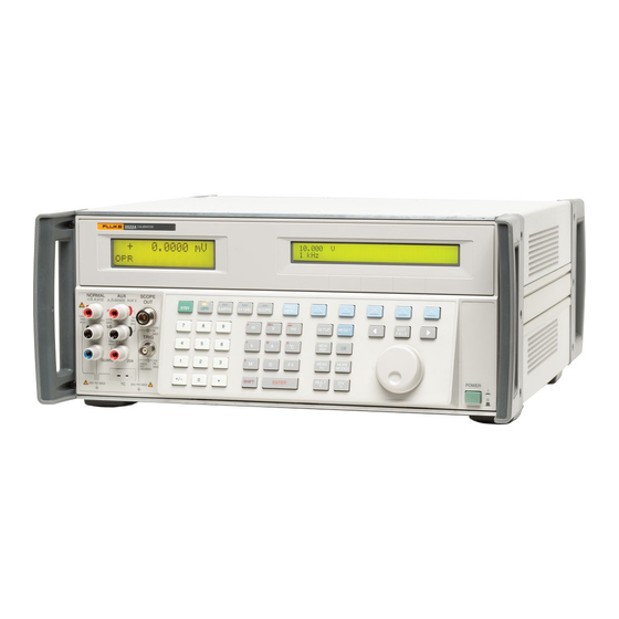
Fluke 5520A Service Operator's Manual (420 pages)
Multi-Product Calibrator
Brand:
Fluke
| Category:
Test Equipment
| Size: 2.27 MB
Table of Contents
Table of Contents
5
Introduction and Specifications
17
Introduction
19
Operation Overview
20
Local Operation
20
Remote Operation (RS-232)
20
Remote Operation (IEEE-488)
21
Where to Go from here
22
Instruction Manuals
23
5520A Operators Manual
24
5520A Operators Guide
24
5520A Programmers Guide
24
5520A Service Manual
24
Specifications
25
General Specifications
26
DC Voltage Specifications
27
DC Current Specifications
28
Resistance Specifications
30
AC Voltage (Sine Wave) Specifications
31
AC Current (Sine Wave) Specifications
33
Capacitance Specifications
35
Temperature Calibration (Thermocouple) Specifications
36
Temperature Calibration (RTD) Specifications
37
DC Power Specification Summary
38
Power and Dual Output Limit Specifications
39
Phase Specifications
40
Calculating Power Uncertainty
41
Additional Specifications
42
Frequency Specifications
42
Harmonics (2Nd to 50Th) Specifications
43
AC Voltage (Sine Wave) Extended Bandwidth Specifications
44
AC Voltage (Non-Sine Wave) Specifications
45
AC Voltage, DC Offset Specifications
46
AC Voltage, Square Wave Characteristics
47
AC Voltage, Triangle Wave Characteristics (Typical)
47
AC Current (Sine Wave) Extended Bandwidth Specifications
47
AC Current (Non-Sine Wave) Specifications
48
AC Current, Square Wave Characteristics (Typical)
50
AC Current, Triangle Wave Characteristics (Typical)
50
Preparing for Operation
51
Introduction
53
Unpacking and Inspection
53
Replacing the Fuse
54
Selecting Line Voltage
54
Connecting to Line Power
55
Selecting Line Frequency
55
Service Information
57
Placement and Rack Mounting
58
Cooling Considerations
58
Features
59
Introduction
61
Front Panel Features
61
Rear Panel Features
61
Softkey Menu Trees
61
Chapter 4 Front Panel Operation
81
Introduction
83
Turning on the Calibrator
83
Using the Softkeys
84
Warming up the Calibrator
84
Using the Instrument Setup Menu
85
Using the Setup Menu
85
Utility Functions Menu
85
Resetting the Calibrator
86
Using the Format EEPROM Menu
86
Zeroing the Calibrator
86
Using the Operate and Standby Modes
88
Connecting the Calibrator to a UUT
89
Recommended Cable and Connector Types
89
Earth
90
External Guard
90
When to Use EARTH and EXGRD
90
Four-Wire Versus Two-Wire Connections
91
Cable Connection Instructions
92
RMS Versus P-P Amplitude
97
Auto Range Versus Locked Range
98
Setting DC Voltage Output
99
Setting the Output
99
Setting AC Voltage Output
100
Sine Wave
127
Square Wave
127
Triangle Wave
127
Setting Harmonics
128
Truncated Sine Wave
128
Adjusting the Phase
129
Entering a Phase Angle
130
Entering a Power Factor
131
Entering a DC Offset
132
Editing and Error Output Settings
133
Editing the Output Setting
133
Displaying the UUT Error
134
Using Multiply and Divide
134
Setting Output Limits
135
Setting Voltage and Current Limits
135
Measuring Pressure
136
Sourcing AC Current with Parallel-Connected 5520As
138
Synchronizing the Calibrator Using 10 Mhz IN/OUT
138
Using an External 10 Mhz Clock
138
Three-Phase Power Calibration
140
Cables
141
Calibrating an 80 Series Handheld Multimeter
141
EARTH Connection
141
Sample Applications
141
Testing the Meter
142
Calibrating the Meter
146
Testing a Model 41 Power Harmonics Analyzer
147
Testing Watts, VA, VAR Performance
147
Testing Harmonics Volts Performance
149
Calibrating a Fluke 51 Thermometer
151
Testing Harmonics Amps Performance
151
Testing the Thermometer
152
Calibrating the Thermometer
153
Chapter 5 Remote Operation
155
Introduction
158
Setting up the IEEE-488 Port for Remote Control
160
IEEE-488 Port Setup Procedure
162
Testing the IEEE-488 Port
163
Host Port Setup Procedure
164
Setting up the RS-232 Host Port for Remote Control
164
Testing RS-232 Host Port Operation Using a Terminal
167
Testing the RS-232 Host Port
167
Testing RS-232 Host Port Operation Using Visual Basic
169
Setting up the RS-232 UUT Port for Remote Control
170
UUT Port Setup Procedure
170
Testing RS-232 UUT Port Operation Via a Terminal
172
Testing the RS-232 UUT Port Via RS-232 Host Port
172
Testing RS-232 UUT Port Operation Using Visual Basic
173
Testing the RS-232 UUT Port Via IEEE-488 Port
174
Changing between Remote and Local Operation
176
Local State
176
Local with Lockout State
176
Remote State
176
Remote with Lockout State
176
Interface Overview
177
IEEE-488 Interface Overview
178
Device-Dependent Commands
180
Types of Commands
180
Using Commands
180
Common Commands
181
Interface Messages (IEEE-488)
181
Query Commands
181
Compound Commands
183
Coupled Commands
183
Overlapped Commands
184
Sequential Commands
184
Command Syntax
187
Parameter Syntax Rules
187
Extra Space or Tab Characters
188
Incoming Character Processing
189
Terminators
189
Response Message Syntax
190
Checking 5520A Status
191
Serial Poll Status Byte (STB)
191
Service Request (SRQ) Line
193
Service Request Enable Register (SRE)
193
Bit Assignments for the ESR and ESE
194
Event Status Enable (ESE) Register
194
Event Status Register (ESR)
194
Programming the STB and SRE
194
Programming the ESR and ESE
195
Bit Assignments for the ISR, ISCR, and ISCE
196
Instrument Status Change Enable Registers
196
Instrument Status Change Registers
196
Instrument Status Register (ISR)
196
Output Queue
198
Programming the ISR, ISCR, and ISCE
198
Error Queue
199
Guidelines for Programming the Calibrator
199
Remote Program Examples
199
Writing an SRQ and Error Handler
200
Using *OPC?, *OPC, and *WAI
201
Verifying a Meter on the IEEE-488 Bus
201
Verifying a Meter on the RS-232 UUT Serial Port
201
Taking a Pressure Measurement
202
Taking a Thermocouple Measurement
202
Input Buffer Operation
203
Using the RS-232 UUT Port to Control an Instrument
203
Chapter 6 Remote Commands
205
Command Summary by Function
207
Common Commands
207
Introduction
207
Error Mode Commands
208
External Connection Commands
208
Oscilloscope Commands
209
Output Commands
209
Host Port Commands
211
UUT Port Commands
211
Setup and Utility Commands
212
Status Commands
213
Thermocouple (TC) Measurement Commands
213
Commands
214
Chapter 7 Maintenance
263
Introduction
265
Replacing the Line Fuse
265
Cleaning the Air Filter
267
General Cleaning
268
Performance Tests
269
Table of Contents
288
Oscilloscope Frequency Response Calibration Procedure
308
Sweeping through a Frequency Range
308
Calibrating the Time Base of an Oscilloscope
310
The Time Marker Function
310
Time Base Marker Calibration Procedure for an Oscilloscope
311
Testing the Trigger SC600 Option
312
Testing Video Triggers
314
Verifying Pulse Capture
315
Input Impedance Measurement
316
Measuring Input Resistance and Capacitance
316
Input Capacitance Measurement
317
Testing Overload Protection
317
Remote Commands and Queries
318
General Commands
319
Edge Function Commands
322
Marker Function Commands
322
Video Function Commands
322
Overload Function Commands
323
Impedance/Capacitance Function Commands
324
DC Voltage Verification
325
Verification Tables
325
AC Voltage Amplitude Verification
326
AC Voltage Frequency Verification
326
Wave Generator Amplitude Verification: 50 Ω Output Impedance
327
Leveled Sine Wave Verification: Amplitude
329
Leveled Sine Wave Verification: Frequency
329
Leveled Sine Wave Verification: Harmonics
330
Leveled Sine Wave Verification: Flatness
331
Edge Verification: Amplitude
337
Edge Verification: Duty Cycle
337
Edge Verification: Frequency
337
Edge Verification: Rise Time
338
Tunnel Diode Pulser Verification
338
Marker Generator Verification
339
Pulse Generator Verification: Period
339
Pulse Generator Verification: Pulse Width
339
Input Impedance Verification: Capacitance
340
Input Impedance Verification: Resistance
340
Table of Contents
341
Introduction
343
Oscilloscope Calibration Option Specifications
344
Volt Function Specifications
344
Edge Function Specifications
345
Leveled Sine Wave Function Specifications
346
Time Marker Function Specifications
347
Wave Generator Specifications
347
Trigger Signal Specifications for the Edge Function
348
Trigger Signal Specifications for the Time Marker Function
348
Oscilloscope Connections
349
Starting the Oscilloscope Calibration Option
350
The Output Signal
350
Adjusting the Output Signal
351
Adjusting Values with the Rotary Knob
351
Keying in a Value
351
Resetting the Oscilloscope Option
352
Using X and D
352
Calibrating the Voltage Amplitude on an Oscilloscope
353
The Volt Function
353
Shortcuts for Setting the Voltage Amplitude
354
The V/DIV Menu
354
Amplitude Calibration Procedure for an Oscilloscope
355
Calibrating the Pulse and Frequency Response on an Oscilloscope
356
The Edge Function
356
Pulse Response Calibration Procedure for an Oscilloscope
357
Shortcuts for Setting the Frequency and Voltage
358
The Leveled Sine Wave Function
358
The more OPTIONS Menu
359
Verification Tables
370
Voltage Function Verification: AC Voltage into a 1 MΩ Load
370
Voltage Function Verification: AC Voltage into a 50 Ω Load
371
Voltage Function Verification: DC Voltage into a 50 Ω Load
372
Edge Function Verification
374
Wave Generator Function Verification: 1 MΩ Load
374
Leveled Sine Wave Function Verification: Amplitude
375
Wave Generator Function Verification: 50 Ω Load
375
Leveled Sine Wave Function Verification: Frequency
379
Marker Generator Function Verification
380
Advertisement
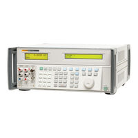
Fluke 5520A Service Service Manual (254 pages)
Multi-Product Calibrator
Brand:
Fluke
| Category:
Test Equipment
| Size: 3.15 MB
Table of Contents
Service Manual
1
Safety Information
3
Table of Contents
5
Introduction and Specifications
19
Introduction
19
Operation Overview
20
Local Operation
20
Remote Operation (RS-232)
20
Remote Operation (IEEE-488)
20
Service Information
21
How to Contact Fluke
21
Specifications
22
General Specifications
23
DC Voltage Specifications
24
DC Current Specifications
25
Resistance Specifications
27
AC Voltage (Sinewave) Specifications
28
AC Current (Sinewave) Specifications
30
Capacitance Specifications
32
Temperature Calibration (Thermocouple) Specifications
33
Temperature Calibration (RTD) Specifications
34
DC Power Specification Summary
35
AC Power (45 Hz to 65 Hz) Specification Summary, PF=1
35
Power and Dual Output Limit Specifications
36
Phase Specifications
37
Calculating Power Uncertainty
38
Additional Specifications
39
Frequency Specifications
39
Harmonics (2Nd to 50Th) Specifications
40
AC Voltage (Sinewave) Extended Bandwidth Specifications
41
AC Voltage (Non-Sinewave) Specifications
42
AC Voltage, DC Offset Specifications
43
AC Voltage, Squarewave Characteristics
44
AC Voltage, Trianglewave Characteristics (Typical)
44
AC Current (Sinewave) Extended Bandwidth Specifications
44
AC Current (Non-Sinewave) Specifications
45
AC Current, Squarewave Characteristics (Typical)
47
AC Current, Trianglewave Characteristics (Typical)
47
Theory of Operation
49
Chapter 2
51
Introduction
51
Encoder Assembly (A2)
52
Synthesized Impedance Assembly (A5)
52
DDS Assembly (A6)
53
Current Assembly (A7)
54
Voltage Assembly (A8)
55
Main CPU Assembly (A9)
56
Power Supplies
56
Outguard Supplies
56
Inguard Supplies
56
Calibration and Verification
57
Chapter 3
59
Introduction
59
Equipment Required for Calibration and Verification
59
Calibration
61
Starting Calibration
61
DC Volts Calibration (NORMAL Output)
62
DC Volts Calibration (30 VDC and Above)
63
AC Volts Calibration (NORMAL Output)
64
Thermocouple Function Calibration
66
DC Current Calibration
67
AC Current Calibration
70
DC Volts Calibration (AUX Output)
76
AC Volts Calibration (AUX Output)
76
Resistance Calibration
77
Capacitance Calibration
80
Calibration Remote Commands
83
Generating a Calibration Report
89
Performance Verification Tests
90
Zeroing the Calibrator
90
Verifying DC Volts (NORMAL Output)
91
Verifying DC Volts (AUX Output)
92
Verifying DC Current
92
Verifying Resistance
94
Verifying AC Voltage (NORMAL Output)
96
Verifying AC Voltage (AUX Output)
98
Verifying AC Current
99
Verifying Capacitance
102
To 110 Mf Capacitance Verification
103
Capacitance Measurement
103
Measurement Uncertainty
107
Verifying Thermocouple Simulation (Sourcing)
108
Verifying Thermocouple Measurement
108
Verifying Phase Accuracy, Volts and AUX Volts
109
Verifying Phase Accuracy, Volts and Current
110
Verifying Frequency Accuracy
111
Maintenance
115
Chapter 4
117
Introduction
117
Access Procedures
117
Removing Analog Modules
117
Removing the Main CPU (A9)
117
Removing Rear Panel Assemblies
118
Removing the Filter PCA (A12)
118
Removing the Encoder (A2) and Display Pcas
118
Removing the Keyboard and Accessing the Output Block
118
Diagnostic Testing
121
Running Diagnostics
121
Testing the Front Panel
121
Complete List of Error Messages
122
How to Obtain Parts
127
Introduction
127
List of Replaceable Parts
127
Introduction
129
How to Obtain Parts
129
Oscilloscope Calibration Options
141
SC600 Option
143
Chapter 6
145
Introduction
145
Maintenance
145
SC600 Specifications
146
Volt Specifications
146
Edge Specifications
147
Leveled Sine Wave Specifications
148
Time Marker Specifications
149
Wave Generator Specifications
149
Pulse Generator Specifications
150
Trigger Signal Specifications (Pulse Function)
150
Trigger Signal Specifications (Time Marker Function)
150
Trigger Signal Specifications (Edge Function)
151
Trigger Signal Specifications (Square Wave Voltage Function)
151
Trigger Signal Specifications
151
Oscilloscope Input Resistance Measurement Specifications
151
Oscilloscope Input Capacitance Measurement Specifications
151
Overload Measurement Specifications
152
Theory of Operation
152
Voltage Mode
152
Edge Mode
152
Leveled Sine Wave Mode
152
Time Marker Mode
153
Wave Generator Mode
153
Input Impedance Mode (Resistance)
153
Input Impedance Mode (Capacitance)
153
Overload Mode
153
Equipment Required for Calibration and Verification
155
SC600 Calibration Setup
157
Calibration and Verification of Square Wave Voltage Functions
158
Overview of HP3458A Operation
158
Setup for SC600 Voltage Square Wave Measurements
158
Setup for SC600 Edge and Wave Gen Square Wave Measurements
160
DC Voltage Calibration
161
AC Voltage Calibration
161
Wave Generator Calibration
162
Edge Amplitude Calibration
162
Leveled Sine Wave Amplitude Calibration
163
Leveled Sine Wave Flatness Calibration
164
Low Frequency Calibration
164
High Frequency Calibration
165
Pulse Width Calibration
165
Measz Calibration
166
Verification
168
DC Voltage Verification
169
Verification at 1 M
169
Verification at 50
169
AC Voltage Amplitude Verification
171
Verification at 50
171
Verification at 1 M
171
Verification at 50
173
AC Voltage Frequency Verification
174
Edge Amplitude Verification
175
Edge Frequency Verification
175
Edge Duty Cycle Verification
176
Edge Rise Time Verification
176
Edge Abberation Verification
178
Tunnel Diode Pulser Drive Amplitude Verification
179
Leveled Sine Wave Amplitude Verification
179
Leveled Sine Wave Frequency Verification
181
Leveled Sine Wave Harmonics Verification
182
Leveled Sine Wave Flatness Verification
184
Equipment Setup for Low Frequency Flatness
184
Equipment Setup for High Frequency Flatness
184
Low Frequency Verification
186
High Frequency Verification
186
Time Marker Verification
188
Wave Generator Verification
189
Verification at 1 M
190
Verification at 50
190
Pulse Width Verification
193
Pulse Period Verification
194
Measz Resistance Verification
194
Measz Capacitance Verification
195
Overload Function Verification
196
SC600 Hardware Adjustments
197
Equipment Required
197
Adjusting the Leveled Sine Wave Function
197
Equipment Setup
197
Adjusting the Leveled Sine Wave VCO Balance
198
Adjusting the Leveled Sine Wave Harmonics
198
Adjusting the Aberrations for the Edge Function
199
Equipment Setup
200
Adjusting the Edge Aberrations
200
SC300 Option
203
Introduction
205
Maintenance
205
SC300 Specifications
206
Voltage Function Specifications
206
Edge Function Specifications
207
Leveled Sine Wave Function Specifications
208
Time Marker Function Specifications
209
Wave Generator Specifications
209
Trigger Signal Specifications for the Time Marker Function
210
Trigger Signal Specifications for the Edge Function
210
Theory of Operation
211
Voltage Mode
211
Edge Mode
211
Leveled Sine Wave Mode
211
Time Marker Mode
212
Wave Generator Mode
212
Equipment Required for Calibration and Verification
214
SC300 Calibration Setup
216
Calibration and Verification of Square Wave Functions
217
Overview of HP3458A Operation
217
Setup for Square Wave Measurements
217
DC Voltage Calibration
218
AC Square Wave Voltage Calibration
219
Edge Amplitude Calibration
220
Leveled Sine Wave Amplitude Calibration
220
Leveled Sine Wave Flatness Calibration
221
Low Frequency Calibration
222
High Frequency Calibration
222
Verification
223
DC Voltage Verification
223
Verification at 1 M
223
Verification at 50
223
Verification at
223
AC Voltage Amplitude Verification
226
Verification at 50
226
Verification at 1 M
226
Verification at 50
228
AC Voltage Frequency Verification
229
Edge Amplitude Verification
230
Edge Frequency Verification
231
Edge Duty Cycle Verification
232
Edge Rise Time Verification
232
Edge Abberation Verification
234
Leveled Sine Wave Amplitude Verification
235
Leveled Sine Wave Frequency Verification
236
Leveled Sine Wave Harmonics Verification
237
Leveled Sine Wave Flatness Verification
239
Equipment Setup for Low Frequency Flatness
239
Equipment Setup for High Frequency Flatness
239
Low Frequency Verification
241
High Frequency Verification
241
Time Marker Verification
243
Wave Generator Verification
244
Verification at 1 M
245
Verification at 50
245
Verification at
245
SC300 Hardware Adjustments
247
Equipment Required
247
Adjusting the Leveled Sine Wave Function
248
Equipment Setup
248
Adjusting the Leveled Sine Wave Harmonics
248
Adjusting the Aberrations for the Edge Function
249
Equipment Setup
249
Adjusting the Edge Aberrations
249
Index
251
Fluke 5520A Service Operator's Manual (88 pages)
multi-product
Brand:
Fluke
| Category:
Test Equipment
| Size: 0.69 MB
Table of Contents
Table of Contents
3
What Is in this Guide
5
Safety Information
5
Ac Power Source
6
How to Contact Fluke
9
Unpacking and Inspecting
9
Replacing the Fuse
10
Selecting Line Voltage
12
Connecting to Line Power
12
Cooling Considerations
13
Front Panel
14
Rear Panel
20
Turning on the Calibrator
23
Warming up the Calibrator
24
Using the Setup Menu
25
Using the Softkeys
25
Instrument Setup Menu
26
Utility Functions Menu
27
Format EEPROM Menu
27
Zeroing the Calibrator
31
Connecting the Calibrator to a UUT
32
Operate and Standby
32
Using the EARTH and EXGRD Keys
33
Earth
33
External Guard
34
Four-Wire and Two-Wire Connections
35
Four-Wire Connection
35
Two-Wire Compensation
35
Compensation off
35
Cable Connection Diagrams
35
RMS Versus P-P Waveforms
40
Auto Range Versus Locked Range
40
Setting Outputs
41
DC Voltage Output
41
AC Voltage Output
42
DC Current Output
44
AC Current Output
45
DC Power Output
47
AC Power Output
49
Dual DC Voltage Output
53
Dual AC Voltage Output
55
Resistance Output
59
Capacitance Output
61
Temperature Simulation (TC)
62
Temperature Simulation (RTD)
65
Measuring a Thermocouple Output
67
Measuring Pressure
70
Waveforms
74
Sinewave (Sine)
74
Trianglewave (Tri)
74
Squarewave (Square)
75
Truncated Sinewave (Truncs)
75
Setting Harmonics
76
Adjusting the Phase
77
Setting a Phase Angle
79
Setting a Power Factor
79
Setting a DC Offset
80
Editing and Error Output Settings
81
Editing the Output Setting
82
Displaying the Output Error
82
Multiplying and Dividing
83
Setting Voltage and Current Limits
83
Synchronizing the Calibrator Using 10 Mhz IN/OUT
84
Using an External 10 Mhz Clock
85
Sourcing Current with Parallel-Connected 5520As
86
Performance Verification
87
Internal Fuses
88
Advertisement
Fluke 5520A Service Programmer's Manual (46 pages)
Multi-Product Calibrator
Brand:
Fluke
| Category:
Test Equipment
| Size: 0.29 MB
Table of Contents
Table of Contents
3
Types of Commands
5
Device-Dependent Commands
5
Common Commands
5
Query Commands
5
Compound Commands
5
Coupled Commands
5
Overlapped Commands
5
Sequential Commands
5
Commands for RS-232 Only
5
Command Syntax
6
General Syntax Rules
6
Units Accepted in Parameters and Responses
7
Incoming Character Processing
8
Terminator Characters
9
Response Message Data Types
9
Checking 5520A Status
10
Status Register Summary
10
STB and SRE
11
ESR and ESE
12
ISR, ISCE, and ISCR
13
Service Request Enable Register (SRE)
14
Output Queue
14
Error Queue
14
Command Summary
15
Common Commands
15
Error Mode Commands
16
External Connection Commands
17
Oscilloscope Commands
18
Output Commands
20
Pressure Measurement Commands
22
RS-232 Host Port Commands
23
RS-232 UUT Port Commands
23
Setup and Utility Commands
24
Status Commands
26
Thermocouple (TC) Measurement Commands
27
Command List
28
Fluke 5520A Service Getting Started (38 pages)
Multi-Product Calibrator
Brand:
Fluke
| Category:
Test Equipment
| Size: 0.45 MB
Table of Contents
Table of Contents
5
Introduction
7
Operation Overview
9
Local Operation
9
Remote Operation (RS-232)
9
Remote Operation (IEEE-488)
9
Where to Go from here
10
Instruction Manuals
11
5520A Getting Started Manual
12
5520A Operators Manual
12
5520A Operators Guide
12
5520A Programmers Guide
12
5520A Service Manual
12
Specifications
13
General Specifications
14
DC Voltage Specifications
15
DC Current Specifications
16
Resistance Specifications
18
AC Voltage (Sine Wave) Specifications
19
AC Current (Sine Wave) Specifications (Cont)
22
Capacitance Specifications
23
Temperature Calibration (Thermocouple) Specifications
24
Temperature Calibration (RTD) Specifications
25
DC Power Specification Summary
26
AC Power (45 Hz to 65 Hz) Specification Summary, PF=1
26
Power and Dual Output Limit Specifications
27
Phase Specifications
28
Calculating Power Uncertainty
29
Frequency Specifications
30
Harmonics (2Nd to 50Th) Specifications
31
AC Voltage (Sine Wave) Extended Bandwidth Specifications
32
AC Voltage (Non-Sine Wave) Specifications
33
AC Voltage, DC Offset Specifications
34
AC Voltage, Square Wave Characteristics
35
AC Voltage, Triangle Wave Characteristics (Typical)
35
AC Current (Sine Wave) Extended Bandwidth Specifications
35
AC Current (Non-Sine Wave) Specifications
36
AC Current, Square Wave Characteristics (Typical)
38
Fluke 5520A Service Manual (30 pages)
Brand:
Fluke
| Category:
Test Equipment
| Size: 0.95 MB
Table of Contents
Specifications
2
General Specifications
3
Electrical Specifications
4
DC Current Specifications
5
Resistance Specifications
7
AC Voltage (Sine Wave) Specifications
8
AC Current (Sine Wave) Specifications
10
Capacitance Specifications
12
Temperature Calibration (Thermocouple) Specifications
13
Temperature Calibration (RTD) Specifications
14
DC Power Specification Summary
15
Power and Dual Output Limit Specifications
15
Phase Specifications
16
Additional Specifications
18
Frequency Specifications
18
Harmonics (2Nd to 50Th) Specifications
18
AC Voltage (Sine Wave) Extended Bandwidth Specifications
19
AC Voltage (Non-Sine Wave) Specifications
19
AC Voltage, DC Offset Specifications
21
AC Voltage, Square Wave Characteristics
21
AC Voltage, Triangle Wave Characteristics (Typical)
21
AC Current (Non-Sine Wave) Specifications
22
AC Current, Square Wave Characteristics (Typical)
23
AC Current, Triangle Wave Characteristics (Typical)
23
Trigger Signal Specifications (Time Marker Function)
25
Time Marker Specifications
25
Trigger Signal Specifications (Edge Function)
26
Advertisement
Related Products
Fluke 5522A Operators
Fluke 5522A-PQ
Fluke 5522A-PQ/1G
Fluke 5522A/1GHZ
Fluke 5522A-PQ/6
FLUKE 5500A
Fluke 5502E
Fluke 5502A
Fluke 5514B-70M-EP
Fluke 5500E
Fluke Categories
Measuring Instruments
Test Equipment
Multimeter
Thermometer
Laboratory Equipment
More Fluke Manuals
Login
Sign In
OR
Sign in with Facebook
Sign in with Google
Upload manual
Upload from disk
Upload from URL