Sign In
Upload
Manuals
Brands
Eaton Manuals
DC Drives
PowerXL DA1
Eaton PowerXL DA1 Manuals
Manuals and User Guides for Eaton PowerXL DA1. We have
4
Eaton PowerXL DA1 manuals available for free PDF download: Installation Manual, Communications Manual
Eaton PowerXL DA1 Installation Manual (203 pages)
Variabe Frequency Drives
Brand:
Eaton
| Category:
DC Drives
| Size: 8 MB
Table of Contents
Table of Contents
5
About this Manual
9
List of Revisions
9
Target Group
9
Hazard Warnings of Material Damages
10
Hazard Warnings of Personal Injury
10
Tips
10
Writing Conventions
10
Abbreviations
11
Documents with Additional Information
11
Mains Supply Voltages
12
Unit of Measurement
12
1 DA1 Device Series
13
Introduction
13
System Overview
15
Checking the Delivery
16
Rated Operational Data
18
Rating Data on the Nameplate
18
Catalog Number Selection
20
Features
22
Description
27
Degree of Protection IP20 (FS2, FS3)
27
Degree of Protection IP20 (FS8)
28
Degree of Protection IP55 (FS4, FS5, FS6, FS7)
29
Degree of Protection IP66 (FS2, FS3)
30
Voltage Categories
31
Selection Criteria
34
Output Reduction (Derating)
36
Proper Use
38
Maintenance and Inspection
39
Storage
39
Charging the Internal DC Link Capacitors
40
Service and Warranty
40
2 Engineering
41
Introduction
41
Electrical Power Network
43
Mains Connection and Network Configuration
43
Mains Voltage and Frequency
44
Voltage Balance
44
Total Harmonic Distortion (THD)
45
Idle Power Compensation Devices
45
Safety and Switching
46
Disconnecting Device
46
Fuses
46
Cable Cross-Sections
47
Residual Current Circuit-Breaker
48
Mains Contactors
49
Using a Bypass Connection
50
Mains Chokes
51
Radio Interference Suppression Filter
52
Braking Resistances
53
Motor Chokes
56
Sine Filter
57
Three-Phase Motor
58
Motor Selection
58
Circuit Types with Three-Phase Motors
59
Connecting Motors in Parallel
60
Single-Phase AC Motors
62
Connecting EX Motors
62
Synchronous, Reluctance, and PM Motors
62
STO Function
63
Overview
63
TÜV Certification
64
Safety Relay Specification
64
STO-Compatible Installation
65
STO Function Pick-Up Time
67
STO Function Parameters
68
Fault Messages
71
STO Function Checklist
71
Regular Maintenance
72
Safe Stop" Function
72
3 Installation
75
Introduction
75
Mounting Position
75
Mounting
76
Mounting Position
77
Cooling Measures
77
Fixing
81
Control Panel Installation
84
IP66/NEMA4X Degree of Protection
85
EMC Installation
87
EMC Compliance in the Control Panel
87
Earthing
89
Internal Filters (EMC and VAR Screws)
90
VAR Screw
91
Screen Earth Kit
91
EMC Cable Brackets
92
General Installation Diagram
93
Electrical Installation
94
Power Section Connections
95
Connection on Control Section
108
Block Diagrams
118
Da1-12
119
Da1-32
120
Da1-32
121
Da1-32
122
Da1-34370
123
Da1-35
124
Da1-35
125
Da1-35
126
Da1-12
127
Da1-32
128
Da1-35
129
Insulation Testing
130
Protection against Electric Shock
131
4 Operation
133
Checklist for Commissioning
133
Hazard Warnings for Operation
134
Commissioning with Control Signal Terminals (Default Settings)
135
Handling the Keypad
138
Operating Unit Elements
138
Adjust Parameters
140
Resetting Parameters (RESET)
140
5 Fault Messages
141
Introduction
141
Acknowledge Fault (Reset)
141
Fault List
142
6 Technical Data
147
General Rating Data
147
Specific Rated Operational Data
151
Da1-12
151
Da1-32
152
Da1-34
155
Da1-35
158
Dimensions
161
Frame Sizes FS2 and FS3 in IP20
161
Frame Sizes FS4 to FS7 in IP55
162
Frame Size FS8 in IP20
163
Frame Sizes FS2 and FS3 in IP66
164
Cable Cross-Sections
165
Fuses
168
Mains Contactors
172
Mains Chokes
176
Radio Interference Suppression Filter
180
Braking Resistances
186
Motor Chokes
192
Sine Filter
194
All-Pole Sine Filters
196
7 Accessories
199
List of Accessories
199
Alphabetical Index
201
Advertisement
Eaton PowerXL DA1 Installation Manual (203 pages)
Variabe Frequency Drives
Brand:
Eaton
| Category:
DC Drives
| Size: 7 MB
Table of Contents
Table of Contents
5
About this Manual
9
Target Group
9
Change Protocol
10
Hazard Warnings of Material Damages
11
Hazard Warnings of Personal Injury
11
Tips
11
Writing Conventions
11
Abbreviations
12
Documents with Additional Information
12
Mains Supply Voltages
13
Units of Measurement
13
1 DA1 Device Series
15
Introduction
15
System Overview
16
Checking the Delivery
17
Rated Operational Data
19
Rated Operational Data on the Rating Plate
19
Catalog Number Selection
21
Features
23
Designation
29
IP20 Protection IP20 (FS2, FS3, FS4, FS5)
29
IP20 Protection (FS8)
30
IP55 Protection IP55 (FS4, FS5, FS6, FS7)
31
IP66 Protection (FS2, FS3)
32
Voltage Classes
33
Da1-12
33
Da1-32
34
Da1-34
35
Da1-35
36
Selection Criteria
37
Output Reduction (Derating)
39
Proper Use
41
Maintenance and Inspection
42
Replacement of the Device Fan for Sizes FS4 and FS5 (IP20)
43
Storage
46
Charging the Internal DC Link Capacitors
47
Service and Warranty
47
2 Engineering
49
Introduction
49
Electrical Power Network
51
Mains Connection and Configuration
51
Mains Voltage and Frequency
52
Voltage Balance
53
Total Harmonic Distortion (THD)
53
Reactive Power Compensation Devices
54
Safety and Switching
55
Disconnecting Device
55
Fuses
55
Cable Cross-Sections
56
Residual Current Device (RCD)
57
Mains Contactors
58
Using Abypass Connection
59
Mains Chokes
60
Radio Interference Suppression Filter
61
Brake Resistors
62
Motor Chokes
65
Sine Wave Filters
66
Three-Phase Motor
67
Motor Selection
67
Circuit Types Withthree-Phase Motors
68
Connecting Motors in Parallel
69
Single-Phase Acmotors
71
Connecting EX Motors
71
Synchronous, Reluctance, and PM Motors
71
STO Function
72
Overview
72
TÜV Certification
73
Specification of the Safety Relay
73
STO-Compatible Installation
74
STO Function Pick-Up Time
77
STO Function Parameters
77
Error Messages
80
STO Function Checklist
80
Regular Maintenance
81
Safe Stop"Function
81
3 Installation
83
Introduction
83
Installation Position
83
Assembly
84
Position of Installation
85
Cooling Measures
85
Fixing
89
Control Panel Installation
92
IP66 / NEMA4X Protection
93
EMC Installation
95
EMC Measures in the Control Panel
95
Grounding
97
Internal Filters (EMC and VAR Screws)
98
VAR Screw
99
Shielding
99
EMC Cable Brackets
100
General Installation Diagram
101
Electrical Installation
102
Connection to Thepower Section
103
Connection to Control Section
116
Block Diagrams
126
Da1
127
Da1
128
Da1-34370
129
Da1
130
Insulation Testing
131
Protection against Electric Shock
132
4 Operation
133
Checklist for Commissioning
133
Operational Hazard Warnings
134
Commissioning with Control Signal Terminals (Default Settings)
135
Using the Operating Unit
138
Operating Unit Elements
138
Setting Parameters
140
Resetting Parameters (RESET)
140
5 Error Messages
141
Introduction
141
Acknowledge Error (Reset)
141
Error List
142
6 Specifications
147
General Rating Data
147
Specific Rated Operational Data
152
Da1-12
152
Da1-32
153
Da1-34
156
Da1-35
159
Dimensions and Frame Sizes
162
Frame Sizes FS2, FS3, FS4 and FS5 for IP20
162
Sizes FS4 to FS7 for IP55
163
Size FS8 for IP20
164
Sizes FS2 and FS3 for IP66
165
Cable Cross-Sections
166
Fuses
169
Mains Contactors
173
Mains Chokes
177
Radio Interference Suppression Filter
181
Braking Resistors
187
Motor Chokes
193
Sine Filters
195
All-Pole Sine Filter
197
7 Accessories
199
List of Accessories
199
Alphabetical Index
201
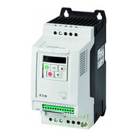
Eaton PowerXL DA1 Communications Manual (85 pages)
Variable Frequency Drives/Variable Speed Starters, CANopen Communication
Brand:
Eaton
| Category:
DC Drives
| Size: 2 MB
Table of Contents
Table of Contents
5
About this Manual
7
List of Revisions
7
Target Group
7
Hazard Warnings of Material Damages
8
Hazard Warnings of Personal Injury
8
Writing Conventions
8
Abbreviations
12
Units of Measurement
12
1 Engineering
13
Technical Data
14
References
14
Data Types
14
2 Installation
15
RJ 45 Interface
15
Install Field Bus
16
COM Port
17
Bus Termination Resistor
17
Baud Rate
18
3 Commissioning
19
Hardware Enable Signal
19
4 Canopen Communication Settings
21
Parameters that Need to be Configured on DA1 Devices
21
Parameters that Need to be Configured on DC1 Devices
23
Parameters that Need to be Configured on DE11 Devices
24
Configuration of the Control Signal Terminals
25
Control Signal Terminal Configuration for DA1
27
Ariable Frequency Drives
27
Control Signal Terminal Configuration for DC1 Variable Frequency Drives
28
Control Signal Terminal Configuration for DC1
29
Control Signal Terminal Configuration for DE11 Variable Speed Starters
30
Object Directory
31
EDS File
31
Transmission Type
31
Communication-Specific Objects
32
Server SDO Parameter
33
Receive Pdos
35
Transmit Pdos
36
Manufacturer-Specific Objects on DA1 Devices
37
Manufacturer-Specific Objects on DC1 Devices
39
Manufacturer-Specific Objects on DC1
40
Manufacturer-Specific Objects on DE11 Devices
41
Fault Messages
42
Parameters
44
Parameters on DA1 Devices
45
Parameters on DC1 Devices
54
Parameters on DC1
56
Parameters on DE11 Devices
62
5 Application Example
65
Canopen Fieldbus Connection on DA1 Variable Frequency Drives
65
Setting up the PLC
65
Materials Required
65
Software
65
Hardware
66
Parameter Settings on DA1 Device
66
PLC Connection
66
PLC Configuration
67
Alphabetical Index
85
Advertisement
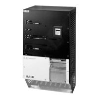
Eaton PowerXL DA1 Communications Manual (63 pages)
Modbus RTU for Variable Frequency Drives/Variable Speed Starters
Brand:
Eaton
| Category:
DC Drives
| Size: 0 MB
Table of Contents
Table of Contents
5
About this Manual
7
List of Revisions
7
Target Group
7
Hazard Warnings of Material Damages
8
Hazard Warnings of Personal Injury
8
Writing Conventions
8
1 Engineering
11
2 Modbus RTU
13
General
13
Communications
13
RJ 45 Interface
15
Enable
16
Data Format
16
Communication Parameters
17
Communication Parameters for DA1 Variable Frequency Drives
18
Communication Parameters for DC1 Variable Frequency Drives
20
Communication Parameters for DE1 Variable Speed Starters
21
Configuration of the Control Signal Terminals
22
Control Signal Terminal Configuration for DA1 Variable Frequency Drives
24
Control Signal Terminal Configuration for DC1 Variable Frequency Drives
25
Control Signal Terminal Configuration for DC1
26
Control Signal Terminal Configuration for DE1 Variable Speed Starters
27
Operating Mode Modbus RTU
29
Structure of the Master Request
30
Structure of the Slave Response
31
Modbus: Register Mapping
32
Input Process Data
33
Output Process Data
35
Explanation of Function Code
44
3 Parameter
47
Parameters for DA1 Variable Frequency Drives
47
Parameters for DC1 Variable Frequency Drives
56
Parameters for DC1
58
Parameters for DE1 Variable Speed Starters
61
Alphabetical Index
63
Advertisement
Related Products
Eaton DA1-32 Series
Eaton DA1-32024 Series
Eaton DA1-35 Series
Eaton DA1-34 Series
Eaton DA1-32030 Series
Eaton DA1-32046 Series
Eaton DA1-32061 Series
Eaton DA1-32072 Series
Eaton DA1-32090 Series
Eaton DA1-32150 Series
Eaton Categories
UPS
Circuit breakers
Switch
Industrial Equipment
Industrial Electrical
More Eaton Manuals
Login
Sign In
OR
Sign in with Facebook
Sign in with Google
Upload manual
Upload from disk
Upload from URL