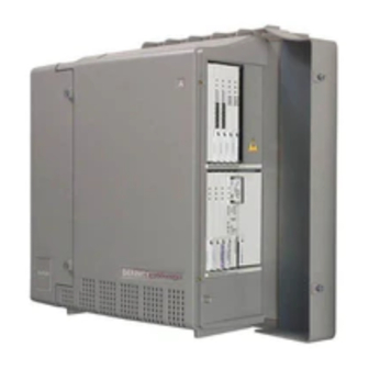
Sign In
Upload
Manuals
Brands
Avaya Manuals
Gateway
CMC1
Avaya CMC1 Manuals
Manuals and User Guides for Avaya CMC1. We have
6
Avaya CMC1 manuals available for free PDF download: Maintenance Procedures, Installation, Upgrades And Additions, Installation Manual, Quick Start Manual
Avaya CMC1 Installation, Upgrades And Additions (370 pages)
Brand:
Avaya
| Category:
Gateway
| Size: 5 MB
Table of Contents
Table of Contents
5
Issue 10 June 2005
17
About this Book
19
Conventions Used in this Book
19
General
19
Typographic
19
Admonishments
20
Physical Dimensions
21
Trademarks
21
How to Get this Book
21
On the Web
21
Non-Web
22
Where to Get Additional Help
22
Tell Us What You Think
23
Security Issues
24
Antistatic Protection
24
Remove/Install Circuit Packs
24
Chapter 1: Installing and Cabling the Cabinets
25
Read this First
25
License File
25
Pre-Installation Checklist
25
Go to the RFA Website
27
No Direct Connection
27
If You Have Problems with RFA
28
Check Customer's Order
29
Correcting Shipping Errors
29
Unpack and Inspect
29
Comcodes for CMC1
31
Install the System Cabinets
34
Set the Carrier Address ID - All Cabinets
34
Floor-Mount the Cabinet
35
Wall-Mount the Cabinets
36
Install Plywood Backing Onto Wall
36
Install Cabinet a - Wall-Mount
37
Install 2 or 3 Vertically Mounted Cabinets
39
Install 2 Cabinets Vertically and 1 Cabinet Horizontally
40
Install Left and Right Panels - Wall-Mount
41
AC Power and Ground
42
Check AC Power
42
Approved Grounds
43
Uninterruptible Power Supply
44
CMC Power Switch
45
Connect Cabinet Grounds and Other Grounds
46
Install the Ground Block
46
Install Coupled Bonding Conductor
48
Connect and Route Cabinet AC Power Cords
48
Cable the System
50
Install Processor Interface Cable - Cabinet a Only and TDM/LAN Bus Terminator
50
Cable the Multi-Cabinet System - Wall-Mount
51
Vertically Mounted System
51
Vertically and Horizontally Mounted System
52
Install Main Distribution Frame (MDF) and External Modem
53
Install the MDF
53
Bottom-Mounted MDF with Modem
53
Top-Mounted MDF
55
Dual Mdfs
56
Install the External Modem
58
Install Equipment Room Hardware
58
Cross-Connect the Cabinets to the MDF
58
Circuit Pack Installation
59
Circuit Pack Slot Loading
59
Off-Premises Circuit Protection
64
Install Sneak Fuse Panels
64
Label the Main Distribution Frame
67
Set up System Access
68
Starting Terminal Emulation
68
Connecting a PC
68
Direct Connection
69
Remote Connection
69
Set Ringing Option
76
Activate and Administer the System
77
Power up System
77
Multi-Cabinet Installations
77
Single Cabinet Installations
77
Deliver or Install the License File
77
System Administration
78
Check Customer Options
78
Check System Status
78
Log into the System
78
Set Country Options
79
Change Craft Password
81
Set Daylight Savings Rules
82
Set Date and Time
83
Administer the Attendant Console
85
Circuit Pack Administration
85
Set System Maintenance Parameters
85
Add Translations
86
Save Translations
86
Install and Wire Telephones and Trunks
86
DCP, Analog, and ISDN-BRI
87
Analog Station or 2-Wire Digital Station Example
88
Analog Tie Trunk Example
88
Digital Tie Trunk Example
89
Collocated DS1 Tie Trunks
90
DS1 Tie Trunk Example
90
3-Pair and 4-Pair Modularity
91
Install Attendant Console - Optional
92
Hard-Wire Bridging
92
Dual Wiring of 2-Wire and 4-Wire Endpoints
93
Install 26B1 Selector Console - Optional
93
Administer IP Stations and Trunks
93
Install and Wire Telephone Power Supplies
93
Typical Adjunct Power Connections
94
Adjunct Power Adapter
94
Adjunct Power Connections End-To-End
94
Auxiliary Power for an Attendant Console
95
1145B2 Power Supply
96
Important Warning for 1145B2 Power Supply
97
Mounting the 1145B2/1146B2 Power Supply
98
Install the Wall-Mounting Plates
101
Mount the 1146B2 Power Distribution Unit
101
Install the Battery Mounting/Wiring
102
Install the Expanded Power Distribution Unit
102
Power up and Test the Power Supply
103
Wire the 1146B2 Power Distribution Unit
104
Reset Leds on Power Distribution Unit
106
1152A1 MID-Span Power Distribution Unit
106
Important Safety Instructions
106
Using the 1152A1 PDU
107
Connect the 1152A1 PDU
108
Connect the Cables
108
P333T-PWR Power over Ethernet Stackable Switch
110
P333T-PWR Switch Important Safety Instructions
110
Connect the P333T-PWR Switch
111
Using the P333T-PWR Switch
111
1151B1 and 1151B2 Power Supplies
113
Important Safety Instructions for 1151B1 and 1151B2 Power Supplies
113
Connect the 1151B1 or 1151B2 Power Supplies
114
Using 1151B1 and 1151B2 Power Supplies
114
Connect External Alarms and Auxiliary Connections
115
Alarm Input
115
Alarm Output
116
Emergency Transfer and Auxiliary Power
116
Telephone Pin Designations
117
CAMA/E911 Installation
118
Configuration
118
Hardware Setup
118
Administration Setup
118
Install the BRI Terminating Resistor
126
Terminating Resistor Adapter
127
Closet Mounted (110RA1-12)
128
Install Multi-Point Adapters
129
BR851-B Adapter (T-Adapter)
130
367A Adapter
131
Basic Multi-Point Installation Distances
132
Install Off-Premises Station Wiring
133
Install Off-Premises or Out-Of-Building Stations
133
Analog Off-Premises Stations
133
Circuit Protectors
135
Digital Out-Of-Building Telephones
136
Install Emergency Transfer Unit and Associated Telephones
138
Install the Emergency Transfer Panel
138
Install Telephone for Power Transfer Unit
144
Connect Modem to Telephone Network
146
External Modem Option Settings
147
Chapter 2: Completing Installation and Cable Pinouts
151
System Administration
151
Alarms and Reporting
151
Resolve Alarms
151
Enable Alarm Origination to INADS
152
Register the Switch for Maintenance
152
Place a Test Call
156
Set Neon Voltage - Ring Ping
156
Installation Completion
157
Power Supply LED Indications
157
TN760E Tie Trunk Option Settings
158
TN464HP and TN2464CP Option Settings
160
Connector and Cable Diagrams - Pinout Charts
162
Processor Interface Cable Pinout
165
Chapter 3: Upgrading R6Csi/R7Csi/R8Csi to Avaya Communication Manager on an Avaya DEFINITY Server CSI
177
Read this First
177
License File
177
7-Digit Dial Plan Expansion
178
Call Management System
178
Service Interruption
178
Contact Network Technicians
178
Translation Card Upgrade Procedures
179
Usable Circuit Packs
179
Software Upgrade
179
Task Table
180
Pre-Upgrade Checklist
181
Go to the RFA Website
183
Have Direct Connection
183
No Direct Connection
183
If You Have Problems with RFA
184
Pre-Upgrade Administration Changes
185
Remove Print Messages Feature Access Code
185
Remove Print-Msgs Buttons
186
Remove MSA Node Names
188
Remove MSA Processor Channels
188
Remove MET Station Administration
189
Check SPE
189
Verify Software Version
189
Verify System Status
190
Disable Scheduled Maintenance and Alarm Origination to INADS
190
Check Link Status
191
Save Translations
191
Save Announcements (if Necessary)
192
Shut down DEFINITY AUDIX System (if Necessary)
192
Replace Circuit Packs
192
Install the License File
193
Pre-Installation
193
Installation (Direct Connection)
194
Installation (no Direct Connection)
194
Display Memory-Configuration
194
Set Daylight Savings Rules
195
Verify the Upgrade
196
Enable Scheduled Maintenance
196
Enable Alarm Origination to INADS
197
Register the Switch for Maintenance
197
Check Customer Options
201
Check Link Status
201
Power up DEFINITY AUDIX System
201
Resolve Alarms
201
Restore Announcements (if Necessary)
201
Check SPE
202
Install Translation Card
202
Save Translations (Post-Upgrade)
202
Save Announcements (if Necessary- Post-Upgrade)
202
Return Equipment
202
DEFINITY AUDIX Power Procedures
203
Power down the AUDIX System
203
Power up the AUDIX System
203
Chapter 4: Upgrading R9Csi/R10Csi/Communication
205
Manager 1.X/2.X to Avaya Communication Manager
205
2.2 on an Avaya DEFINITY Server CSI
205
Read this First
205
License File
205
7-Digit Dial Plan Expansion
205
Service Interruption
206
Call Management System (CMS)
206
Software Compatibility
206
Usable Circuit Packs
207
Wireless Systems
207
Antistatic Protection
207
Task Table
207
Pre-Upgrade Checklist
209
Go to the RFA Website
211
Have Direct Connection
211
No Direct Connection
211
If You Have Problems with RFA
212
Pre-Upgrade Administration Changes
213
Task Description Page
213
Remove Print Messages Feature Access Code
214
Remove Print-Msgs Buttons
214
Remove MSA Node Names
216
Remove MSA Processor Channels
216
Remove MET Station Administration
217
Check SPE
218
Verify Version
218
Verify System Status
218
Disable Scheduled Maintenance and Alarm Origination
219
Check Link Status
220
Save Translations
220
Save Announcements (if Necessary)
221
Upgrade the Software
221
Install the License File
222
Installation (Direct Connection)
222
Pre-Installation
222
Installation (no Direct Connection)
223
Administer No-License/Emergency Numbers
223
Set Daylight Savings Rules
223
Verify the Upgrade
224
Check Link Status
225
Enable Scheduled Maintenance
226
Register the Switch for Maintenance
226
Resolve Alarms
229
Restore Busyouts
229
Restore Announcements
230
Check SPE
230
Save Translations (Post-Upgrade)
230
Save Announcements (Post-Upgrade)
230
Return Equipment
230
Advertisement
Avaya CMC1 Maintenance Procedures (426 pages)
Brand:
Avaya
| Category:
Gateway
| Size: 5 MB
Table of Contents
Procedure
2
Reset Level
4
Table of Contents
5
About this Book
15
Overview
15
Audience
15
Downloading this Book
16
Downloading this Book and Updates from the Web
16
Safety and Security-Alert Labels
16
Electromagnetic Interference
17
Related Resources
17
Safety Precautions
17
International
18
Technical Assistance
18
Within the United States
18
How to Use this Document
19
Organization
19
Sending Us Comments
19
Trademarks
19
Conventions Used in this Document
20
Useful Terms
21
1 Maintenance Strategy
23
Maintenance Objects
23
Maintenance Testing
24
Background Testing
24
Demand Testing
25
Co-Resident DEFINITY LAN Gateway Maintenance
25
Processor C-LAN Maintenance
25
Administration and Maintenance
26
Media Processor (DEFINITY ONE)
26
Alarm and Error Logs
27
Alarm and Error Reporting
27
Alarm Reporting
28
Power Interruptions
29
Nominal Power Holdover
30
Power Interruption Effects
30
External Alarm Leads
31
Protocols
31
OSI Layers
32
Usage
33
Protocol States
35
Connectivity Rules
36
Disconnect Supervision
37
Signaling
37
Transmission Characteristics
38
Service Codes
42
Facility Interface Codes
43
Multimedia Interface (MMI)
44
S8300 and G700 Maintenance Strategy
44
Media Module Maintenance
45
Access to the G700 Media Gateway and S8300 Media Server
46
G700 Media Gateway Processor CLI
46
S8300 Media Server Web Interface
46
DEFINITY Equivalent Elements
47
G700 Server-Controlled Maintenance
47
Layer 2 Switching Processor CLI
47
Capacity Constraints and Feature Limitations
48
Testing
54
Maintenance Features for the G700
57
2 Access and Login Procedures
59
Connection Overview
59
Laptop Settings and Connections
60
Laptop Settings
61
Laptop Connections
64
Connecting through an External Modem
66
Login Methods
71
Logging in to the S8300 Web Interface from Your Laptop
72
Logging in Using a Telnet Session on Your Laptop
72
Logging in to Communication Manager (SAT Screens)
76
Logging in to the Layer-2 Switching Processor
77
Customer Access
79
Logins and Passwords on the S8100
79
Windows 2000 Logins for the Customer
80
Windows 2000 Login Types for the Customer
81
Enabling Windows 2000 Customer Logins
82
Communication Manager Logins for the Customer
83
Avaya Site Administration Configuration
86
Navigating the Command Line Interface
87
Accessing the S8100 Media Server for Maintenance
88
Telnet Session
88
Web Browser Interface
88
Avaya Site Administration
89
3 License and Authentication Files
91
Installing License and Authentication Files
91
Downloading the License and Authentication Files
91
Installing License and Authentication Files
92
License Files for Different Configurations
93
S8300 Media Server
93
S8700 Media Server
93
License File Modes
94
License-Error
94
License-Normal
94
Survivable Configuration
94
License and Options Forms Interactions
95
No-License
95
4 Hardware Configurations
97
Multicarrier Cabinets
97
PNC Cabling Fiber-Optic Hardware
97
EI-To-EI or EI-To-SNI Intercabinet Fiber-Optic Cables
97
EI-To-SNI or EI-To-EI Intracabinet Metallic Cabling
99
DS1 CONV Cabling
99
Circuit Packs
101
Duplication for Reliability
102
Basic Server and IPSI Connections
102
High Reliability Connectivity
102
Critical Reliability Connectivity
103
Standard and High Reliability Configurations
103
Critical Reliability Configuration
107
S8100 Media Server Components and Functionality
107
TN2314 Processor Circuit Pack
107
Virtual Boards and Devices
108
Windows 2000 Platform
108
Backup Procedures
109
GUI Operation
109
G600 and CMC1 Media Gateways Design
112
CMC1 Media Gateway Cabinets
114
G600 Media Gateway Cabinet
116
Ups
117
Circuit Packs
118
G700 with a Media Server System
118
How Does the G700 Fit into Your System
118
5 Server Initialization, Recovery, and Resets
119
S8700 Initialization
119
Active Server's Initialization
120
Standby Server's Initialization
120
S8100 Initialization
121
LED Boot Sequence
121
Communication Manager Initialization
122
Shutdown
123
S8100 Recovery
124
Communication Manager Resets
127
Recovery from Fatal Errors in the S8100
128
Resolving Alarms
129
Link Recovery
130
H.248 Server-To-Gateway Link Recovery
131
H.323 Gateway-To-Endpoint Link Recovery
139
System Resets
152
Reset Level 1 (Warm Restart)
153
Reset Level 2 (Cold-2 Restart)
154
Reset Level 3 (Communication Manager Reboot)
155
Reset Level 5 (Extended Communication Manager Reboot)
156
S8100 System Reset
156
S8300/G700 System Reset
157
6 Troubleshooting
159
Safety Precautions
159
Removing and Restoring EMBEDDED AUDIX Power
160
Electrostatic Discharge
161
Suppressing Alarm Origination
162
Troubleshooting Duplicated Servers
163
Determining the Time of a Spontaneous Interchange
164
Troubleshooting Trunks with Automatic Circuit Assurance
164
Using Busy Verification of Terminals and Trunks
164
LA85 Port Tester
165
Trunk Group Busy/Warning Indicators to Attendant
165
Trunk Identification by Attendant
165
Fiber Link Fault Isolation
167
Isolating Fiber Faults with Loopback Tests
171
Troubleshooting SNI/EI Links with Manual Loop-Back
171
Troubleshooting ATM
173
Initial LED Inspection
174
A500 Switch Diagnostics
176
ATM Administration
178
A500 Administration
182
TN230X Circuit Pack(S)
186
Physical Layer
188
SONET Layer
190
Q.SAAL (Data Link) Layer
191
Q.93B (Network) Layer
192
ATM Call Control
195
Capro Layer
196
Unusual ATM Trouble Conditions
199
Expansion Services Module
201
Troubleshooting Multimedia Call Handling (MMCH)
201
Troubleshooting ISDN-PRI
207
Troubleshooting ISDN-PRI Endpoints (Wideband)
209
Troubleshooting ISDN-BRI / ASAI
212
Troubleshooting ISDN-PRI Test Calls
215
Asynchronous Method
216
Synchronous Method
216
Troubleshooting the Outgoing ISDN-Testcall Command
218
Avaya CMC1 Installation Manual (346 pages)
Installation, Upgrades and Additions for Media Gateways
Brand:
Avaya
| Category:
Gateway
| Size: 4 MB
Table of Contents
Table of Contents
5
About this Book
15
Conventions Used in this Book
15
General
15
June
15
Typographic
15
Admonishments
16
Physical Dimensions
16
Trademarks
16
How to Get this Book
17
Non-Web
17
On the Web
17
Where to Get Additional Help
17
Tell Us What You Think
18
Antistatic Protection
19
Issue
19
Remove/Install Circuit Packs
19
Security Issues
19
Installing and Cabling the Cabinets
21
Read this First
21
License File
21
Pre-Installation Checklist
21
If You Have Problems with Rfa
23
Check Customer's Order
24
Correcting Shipping Errors
24
Unpack and Inspect
24
Comcodes for CMC1
26
Install the System Cabinets
29
Set the Carrier Address ID - All Cabinets
29
Floor-Mount the Cabinet
30
Wall-Mount the Cabinets
31
Install Cabinet a - Wall-Mount
32
Install Left and Right Panels - Wall-Mount
36
AC Power and Ground
36
Approved Grounds
37
Uninterruptible Power Supply
38
CMC Power Switch
39
Connect Cabinet Grounds and Other Grounds
39
Connect and Route Cabinet AC Power Cords
42
Install Coupled Bonding Conductor
42
Cable the System
44
Install Processor Interface Cable - Cabinet a Only and TDM/LAN Bus Terminator
44
Cable the Multi-Cabinet System - Wall-Mount
45
Install Main Distribution Frame (MDF) and External Modem
47
Install the MDF
47
Install the External Modem
51
Install Equipment Room Hardware
52
Circuit Pack Installation
52
Cross-Connect the Cabinets to the MDF
52
Off-Premises Circuit Protection
56
Install Sneak Fuse Panels
57
Label the Main Distribution Frame
59
Set up System Access
59
Starting Terminal Emulation
59
Connecting a PC
60
Remote Connection
61
Set Ringing Option
66
Activate and Administer the System
66
Power up System
66
Administer No-License/Emergency Numbers
67
Deliver or Install the License File
67
System Administration
68
Set Daylight Savings Rules
71
Set Date and Time
72
Save Translations
74
Install and Wire Telephones and Trunks
75
DCP, Analog, and ISDN-BRI
75
Analog Tie Trunk Example
77
Digital Tie Trunk Example
77
Collocated Ds1 Tie Trunks
78
Ds1 Tie Trunk Example
78
Install Attendant Console - Optional
80
Administer IP Stations and Trunks
81
Install 26B1 Selector Console - Optional
81
Install and Wire Telephone Power Supplies
81
Typical Adjunct Power Connections
82
Auxiliary Power for an Attendant Console
83
1145B2 Power Supply
84
Important Warning for 1145B2 Power Supply
85
1152A1 MID-Span Power Distribution Unit
93
Connect the Cables
94
P333T-PWR Power over Ethernet Stackable Switch
96
1151B1 and 1151B2 Power Supplies
99
Using 1151B1 and 1151B2 Power Supplies
100
Connect External Alarms and Auxiliary Connections
101
Telephone Pin Designations
102
Installation, Upgrades and Additions for Avaya CMC1 Media Gateways June
103
CAMA/E911 Installation
103
Administration Setup
103
Configuration
103
Hardware Setup
103
Install the BRI Terminating Resistor
109
Terminating Resistor Adapter
110
Closet Mounted (110RA1-12)
111
Install Multi-Point Adapters
112
BR851-B Adapter (T-Adapter)
113
367A Adapter
114
Basic Multi-Point Installation Distances
115
Install Off-Premises Station Wiring
116
Install Emergency Transfer Unit and Associated Telephones
121
Install the Emergency Transfer Panel
121
Connect Modem to Telephone Network
128
External Modem Option Settings
129
Completing Installation and Cable Pinouts
133
System Administration
133
Alarms and Reporting
133
Resolve Alarms
133
Enable Alarm Origination to INADS
133
Register the Switch for Maintenance
134
Place a Test Call
137
Set Neon Voltage Ring Ping
137
Installation Completion
138
Power Supply LED Indications
138
TN760E Tie Trunk Option Settings
138
TN464F/GP and TN2464BP Option Settings
140
Connector and Cable Diagrams - Pinout Charts
142
Processor Interface Cable Pinout
144
Upgrading R6Csi/R7Csi/R8Csi to Avaya Communication Manager on an Avaya DEFINITY Server CSI
155
Read this First
155
License File
155
7-Digit Dial Plan Expansion
155
Call Management System
156
Service Interruption
156
Contact Network Technicians
156
Translation Card Upgrade Procedures
156
Usable Circuit Packs
156
Software Upgrade
156
Task Table
157
Pre-Upgrade Checklist
158
Task Description Page
158
Pre-Upgrade Administration Changes
161
Check SPE
165
Disable Scheduled Maintenance and Alarm Origination to INADS
165
Verify Software Version
165
Verify System Status
165
Check Link Status
166
Save Announcements (if Necessary)
166
Save Translations
166
Replace Circuit Packs
167
Shut down DEFINITY AUDIX System (if Necessary)
167
Install the License File
168
Administer No-License/Emergency Numbers
169
Display Memory-Configuration
169
Set Daylight Savings Rules
169
Verify the Upgrade
170
Enable Alarm Origination to INADS
171
Enable Scheduled Maintenance
171
Register the Switch for Maintenance
171
Check Customer Options
174
Check Link Status
174
Power up DEFINITY AUDIX System
174
Resolve Alarms
174
Check SPE
175
Install Translation Card
175
Restore Announcements (if Necessary)
175
Return Equipment
175
Save Announcements (if Necessary- Post-Upgrade)
175
Save Translations (Post-Upgrade)
175
DEFINITY AUDIX Power Procedures
176
Upgrading R9Csi/R10Csi to Avaya Communication Manager on an Avaya DEFINITY Server CSI
177
Read this First
177
License File
177
7-Digit Dial Plan Expansion
177
Service Interruption
177
Call Management System (CMS)
178
Software Compatibility
178
Usable Circuit Packs
178
Wireless Systems
178
Antistatic Protection
178
Task Table
179
Pre-Upgrade Checklist
180
Go to the RFA Website
181
Pre-Upgrade Administration Changes
183
Check SPE
187
Verify System Status
187
Verify Version
187
Check Link Status
188
Disable Scheduled Maintenance and Alarm Origination
188
Save Announcements (if Necessary)
189
Save Translations
189
Upgrade the Software
189
Install the License File
190
Administer No-License/Emergency Numbers
191
Set Daylight Savings Rules
191
Check Link Status
192
Verify the Upgrade
192
Enable Scheduled Maintenance
193
Register the Switch for Maintenance
193
Check SPE
196
Resolve Alarms
196
Restore Announcements
196
Restore Busyouts
196
Return Equipment
196
Save Announcements (Post-Upgrade)
196
Save Translations (Post-Upgrade)
196
Advertisement
Avaya CMC1 Installation Manual (324 pages)
Avaya CMC1 Media Gateways
Brand:
Avaya
| Category:
Gateway
| Size: 4 MB
Table of Contents
Table of Contents
5
Issue
8
About this Book
9
Conventions Used in this Book
9
Trademarks
11
How to Get this Book
11
Where to Get Additional Help
12
Tell Us What You Think
13
Security Issues
13
Antistatic Protection
13
Remove/Install Circuit Packs
13
1 Installing and Cabling the Cabinets
15
Read this First
15
Check Customer's Order
19
Correcting Shipping Errors
19
Unpack and Inspect
19
Comcodes for CMC1
21
Install the System Cabinets
24
AC Power and Ground
32
Cable the System
40
Install Main Distribution Frame (MDF) and External Modem
43
Install Equipment Room Hardware
49
Set up System Access
58
Set Ringing Option
66
Activate and Administer the System
67
Set Date and Time
73
Install and Wire Telephones and Trunks
77
Install and Wire Telephone Power Supplies
84
Table of Contents
88
Install the Wall-Mounting Plates
93
Mount the 1146B2 Power Distribution Unit
93
On Page
93
Install the Battery Mounting/Wiring
94
Install the Expanded Power Distribution Unit
94
Power up and Test the Power Supply
95
Wire the 1146B2 Power Distribution Unit
96
Reset Leds on Power Distribution Unit
98
Connect External Alarms and Auxiliary Connections
108
Telephone Pin Designations
109
CAMA/E911 Installation
110
Install the BRI Terminating Resistor
117
Install Multi-Point Adapters
121
Install Off-Premises Station Wiring
124
Install Emergency Transfer Unit and Associated Telephones
129
Connect Modem to Telephone Network
137
2 Completing Installation and Cable Pinouts
141
System Administration
141
Alarms and Reporting
142
Place a Test Call
146
Set Neon Voltage - Ring Ping
147
Installation Completion
148
Power Supply LED Indications
148
TN760D Tie Trunk Option Settings
149
TN464F/GP and TN2464BP Option Settings
151
Connector and Cable Diagrams - Pinout Charts
153
Upgrading R6Csi/R7Csi/R8Csi to Avaya Communication Manager on an Avaya DEFINITY Server CSI
165
Read this First
165
Section 3
168
Task Table
168
Pre-Upgrade Checklist
169
Task Description Page
169
Task Table
169
Check SPE
176
Verify Software Version
176
Disable Scheduled Maintenance and Alarm Origination to INADS
177
Verify System Status
177
Check Link Status
178
Save Announcements (if Necessary)
178
Save Translations
178
Replace Circuit Packs
179
Shut down DEFINITY AUDIX System (if Necessary)
179
Install the License File
180
Display Memory-Configuration
181
Set Daylight Savings Rules
181
Verify the Upgrade
182
Enable Alarm Origination to INADS
183
Enable Scheduled Maintenance
183
Register the Switch for Maintenance
183
Check Customer Options
187
Check Link Status
187
Check SPE
187
Install Translation Card
187
Power up DEFINITY AUDIX System
187
Resolve Alarms
187
Restore Announcements (if Necessary)
187
DEFINITY AUDIX Power Procedures
188
Upgrading R9/R10/ Avaya Communication Manager 1.X Csi to Avaya Communication Manager
191
Read this First
191
Avaya CMC1 Installation, Upgrades And Additions (314 pages)
Brand:
Avaya
| Category:
Gateway
| Size: 5 MB
Table of Contents
Table of Contents
5
About this Book
9
Conventions Used in this Book
9
Trademarks
11
How to Get this Book
11
Where to Get Additional Help
12
Tell Us What You Think
13
Security Issues
13
Antistatic Protection
13
Remove/Install Circuit Packs
13
Installing and Cabling the Cabinets
15
Read this First
15
Check Customer's Order
19
Correcting Shipping Errors
19
Unpack and Inspect
19
Comcodes for CMC1
21
Install the System Cabinets
24
AC Power and Ground
32
Cable the System
40
Install Main Distribution Frame (MDF) and External Modem
43
Install Equipment Room Hardware
50
Set up System Access
59
Set Ringing Option
69
Activate and Administer the System
70
Install and Wire Telephones and Other Equipment
80
Connect External Alarms and Auxiliary Connections
91
Telephone Pin Designations
92
CAMA/E911 Installation
93
Install the BRI Terminating Resistor
100
Install Multi-Point Adapters
104
Install Off-Premises Station Wiring
107
Install Emergency Transfer Unit and Associated Telephones
112
Connect Modem to Telephone Network
120
Completing Installation and Cable Pinouts
125
System Administration
125
Alarms and Reporting
126
Place a Test Call
130
Set Neon Voltage - Ring Ping
131
Installation Completion
132
Power Supply LED Indications
132
TN760D Tie Trunk Option Settings
133
TN464F/GP and TN2464BP Option Settings
135
Connector and Cable Diagrams - Pinout Charts
137
Upgrading R6Csi/R7Csi/R8Csi to
149
Avaya Multivantage Software on an Avaya DEFINITY Server CSI
149
Read this First
149
Section 1
152
Task Table
152
Table 3-1. Tasks List
153
Task Description Page
153
Pre-Upgrade Checklist
153
Check SPE
161
Verify Software Version
161
Verify System Status
161
Disable Scheduled Maintenance and Alarm Origination to INADS
162
Check Link Status
162
Disable TTI (Do Not Skip this Section!)
163
Check TTI Status
163
Save Translations
163
Save Announcements (if Necessary)
163
Shut down DEFINITY AUDIX System (if Necessary)
164
Replace Circuit Packs
164
Install the License File
165
Display Memory-Configuration
166
Set Daylight Savings Rules
167
Verify the Upgrade
167
Re-Enable TTI
168
Enable Scheduled Maintenance
168
Enable Alarm Origination to INADS
169
Register the Switch for Maintenance
169
Check Customer Options
173
Check Link Status
173
Power up DEFINITY AUDIX System
173
Resolve Alarms
174
Restore Announcements (if Necessary)
174
DEFINITY AUDIX Power Procedures
175
Upgrading R9Csi/R10Csi to
177
Avaya Multivantage Software on an Avaya DEFINITY Server CSI
177
Read this First
177
Avaya CMC1 Quick Start Manual (22 pages)
for Hardware Migration Media Server in an Media Gateway
Brand:
Avaya
| Category:
Server
| Size: 0 MB
Table of Contents
Process and Specifications
3
Verifying the Equipment
5
Installing the Hardware: SNMP Module
10
Installing the Hardware: Mounting Brackets
10
Configuring the UPS
18
Powering up the System
21
Troubleshooting
22
Advertisement
Related Products
Avaya CMS
Avaya CPSEE_TSP500
Avaya Customer Interaction Express 1.0 IVR-Editor
Avaya Communication Manager Contact Center
Avaya Compact DECT
Avaya Call Management System
Avaya CS700
Avaya CS 1000M Series
Avaya CS 1000
Avaya CyberGear TA EU
Avaya Categories
IP Phone
Telephone
Server
Switch
Gateway
More Avaya Manuals
Login
Sign In
OR
Sign in with Facebook
Sign in with Google
Upload manual
Upload from disk
Upload from URL