Avaya CMC1 Installation, Upgrades And Additions
Hide thumbs
Also See for CMC1:
- Installation manual (346 pages) ,
- Installation, upgrades and additions (314 pages) ,
- Maintenance procedures (426 pages)
Table of Contents
Advertisement
Quick Links
Download this manual
See also:
Installation Manual
Advertisement
Table of Contents
Troubleshooting

Related Manuals for Avaya CMC1


Summary of Contents for Avaya CMC1
- Page 1 Installation, Upgrades and Additions for Avaya CMC1 Media Gateways 555-233-118 Issue 10 June 2005...
- Page 2 • System administration documents Warranty • Security documents Avaya Inc. provides a limited warranty on this product. Refer to your • Hardware-/software-based security tools sales agreement to establish the terms of the limited warranty. In • Shared information between you and your peers addition, Avaya’s standard warranty language as well as information...
- Page 3 • A reorder tone is received. 04DU9-IKN 6.0Y RJ48C Avaya attests that this registered equipment is capable of providing users access to interstate providers of operator services through the use of 04DU9-ISN 6.0Y RJ48C access codes. Modification of this equipment by call aggregators to block...
- Page 4 Contact the state public utility commission, public service E-mail: totalware@gwsmail.com commission or corporation commission for information. For the most current versions of documentation, go to the Avaya support This equipment, if it uses a telephone receiver, is hearing aid compatible. Web site: http://www.avaya.com/support.
-
Page 5: Table Of Contents
Unpack and Inspect ........Comcodes for CMC1........ - Page 6 Deliver or Install the License File ......6 Installation, Upgrades and Additions for Avaya CMC1 Media Gateways...
- Page 7 Contents System Administration ......Log into the System ......Check System Status .
- Page 8 Circuit Protectors ....... Digital Out-of-Building Telephones..... . 8 Installation, Upgrades and Additions for Avaya CMC1 Media Gateways...
- Page 9 Avaya Communication Manager on an Avaya DEFINITY Server CSI ....177 Read This First ........
- Page 10 Power Up the AUDIX System ......10 Installation, Upgrades and Additions for Avaya CMC1 Media Gateways...
- Page 11 Manager 1.x/2.x to Avaya Communication Manager 2.2 on an Avaya DEFINITY Server CSI ... . 205 Read this first ........
- Page 12 Add Code Calling Access ....... 12 Installation, Upgrades and Additions for Avaya CMC1 Media Gateways...
- Page 13 Contents Add Pooled Modem ........Settings for Modem Connected to Data Module ....Settings for Modem Connected to the Data Terminal Equipment (DTE) .
- Page 14 Installing the 120A3A CSU ......14 Installation, Upgrades and Additions for Avaya CMC1 Media Gateways...
- Page 15 Contents Installing a J58890CG Power Distribution Unit ........Mounting without a backing plate .
- Page 16 INTUITY AUDIX Messaging Systems ..... . . Avaya Modular Messaging System ......
-
Page 17: Issue 10 June 2005
ASAI and DEFINITY LAN Gateway ......Avaya Interactive Response ...... - Page 18 Contents 18 Installation, Upgrades and Additions for Avaya CMC1 Media Gateways...
-
Page 19: About This Book
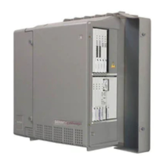
About This Book This document provides procedures to install, upgrade, or make additions to an Avaya CMC1 Media Gateway, which is housed in the Compact Modular Cabinet (CMC1). Conventions used in this book General The following conventions apply to the Avaya DEFINITY Server CSI: The word “system”... -
Page 20: Admonishments
ENTER, RETURN, CANCEL, HELP, NEXT PAGE, etc. In this book we use the terms “telephone” and “voice terminal” to refer to phones. We show commands and screens from the newest Avaya Communication Manager system and refer to the most current books. Please substitute the appropriate commands for your system and refer to the manuals you have available. -
Page 21: Physical Dimensions
) in parentheses. Trademarks All trademarks identified by ® or ™ are registered trademarks or trademarks, respectively, of Avaya Inc. All other trademarks are the property of their respective owners. How to get this book On the Web If you have internet access, you can view and download the latest version of this book. To view the book, you must have a copy of Acrobat Reader. -
Page 22: Non-Web
Outside the United States, click Escalation Lists then click Global Escalation List, which includes phone numbers for the regional Centers of Excellence. If you do not have Web access, use the phone numbers below (Table 22 Installation, Upgrades and Additions for Avaya CMC1 Media Gateways... -
Page 23: Tell Us What You Think
International Technical Assistance Center +905-943-8801 (ITAC) For all international resources, contact your local Avaya authorized dealer for any additional help and questions. Tell us what you think Let us know what you like or don’t like about this book. Although we can’t respond personally to all your feedback, we promise we will read each response we receive. -
Page 24: Security Issues
About This Book Security Issues To ensure the greatest security possible for customers, Avaya Inc. offers services that can reduce toll-fraud liabilities. Contact your Avaya Inc. representative for more security information. Login security is an attribute of the Avaya Communication Manager. Existing passwords expire 24 hours after installation. -
Page 25: Chapter 1: Installing And Cabling The Cabinets
In order to be properly prepared for the installation, have the items listed in Table 2 ready. Table 2: Pre-installation checklist Item Item Software Release Letter Avaya Communication Manager on removable media Extra formatted removable media Authorized wrist grounding strap 1 of 3 Issue 10 June 2005... - Page 26 Instead, existing switch configuration information is captured using the ASD tool and process. Adobe Acrobat Reader application installed on your PC (to read FET and LIT documentation) 2 of 3 26 Installation, Upgrades and Additions for Avaya CMC1 Media Gateways...
-
Page 27: Go To The Rfa Website
The Remote Feature Activation (RFA) website automates some of the upgrade procedures, including generating a License File. 1. At your laptop/PC browser, go to the http://rfa.avaya.com Website: 2. Using your SSO, log in to the RFA website. 3. Follow the links to the RFA Information page. -
Page 28: If You Have Problems With Rfa
EMEA .com APAC RTAC Direct and +65-6872-8686 Business Partners CALA Direct and Business +525-278-7878 Mexico TAC Partners +5511-5185-6655 Brazil TAC +571-616-6077 +5411-4114-4440 Columbia TAC +1-720-444-9998 Argentina TAC Mexico Call Receipt 28 Installation, Upgrades and Additions for Avaya CMC1 Media Gateways... -
Page 29: Check Customer's Order
Check the customer’s order and the shipping packing lists to confirm that all equipment is present. If any equipment is missing, report this to your Avaya Inc. representative. Check the system adjuncts for damage and report all damage according to local shipping instructions. - Page 30 5. #12 x 1-inch shoulder screws 10. 14-in. (35.5 cm) 6 AWG (#40) 6. Processor interface cable (not shipped with (16 mm ) ground wire all cabinets) 11. Single-point ground block 30 Installation, Upgrades and Additions for Avaya CMC1 Media Gateways...
-
Page 31: Comcodes For Cmc1
Comcodes for CMC1 Comcodes for CMC1 Table 4 lists the comcodes for equipment used with the CMC1. Table 4: Comcodes for CMC1 Comcode Description 700225758 Left Panel 847951670 Right Panel 700225360 Right Door 700225766 Left Door 847960002 Processor Interface Cable... - Page 32 105514756 3C1S Solid State 102904893 4B1C Carbon Block with Heat Coil 104401856 4B1E-W Wide Gap Gas Tube with Heat Coil 104386545 4C1S Solid State with Heat Coil 2 of 3 32 Installation, Upgrades and Additions for Avaya CMC1 Media Gateways...
- Page 33 Comcodes for CMC1 Table 4: Comcodes for CMC1 (continued) Comcode Description 406948976 SCP-110 Sneak Current Protector 407216316 220029 Fuse Sneak Current Protector 105581086 4C3S-75 Solid State with Heat Coil 406144907 ITW LINX Gas Tube, Avalanche Suppress 901007120 ITW Linx Ground Bar (used with above)
-
Page 34: Install The System Cabinets
1. Carrier A switch settings 3. Carrier C switch settings 2. Carrier B switch settings 1. Proceed to either Floor-Mount the Cabinet on page 35 or to Wall-Mount the Cabinets page 36. 34 Installation, Upgrades and Additions for Avaya CMC1 Media Gateways... -
Page 35: Floor-Mount The Cabinet
Install the System Cabinets Floor-Mount the Cabinet The cabinet dimensions (with floor pedestal) are 28.5 in. (72.4 cm) high, 24.5 in. (62.2 cm) wide, and 12 in. (30.5 cm) deep. Maintain a service clearance of 12 in. (30.5 cm) on the left, right, and front of the cabinet. -
Page 36: Wall-Mount The Cabinets
2. Install a 3/4-in. (2 cm) thick sheet of 2 x 4-ft (0.6 x 1.2 m) sheet of plywood horizontally onto the wall. Position the plywood to the right of the first sheet, across from Cabinet A. 36 Installation, Upgrades and Additions for Avaya CMC1 Media Gateways... -
Page 37: Install Cabinet A - Wall-Mount
Install the System Cabinets Install Cabinet A — Wall-Mount Figure 4: Left Panel Used as Mounting Template To wall-mount cabinet A: 1. Place the template on the wall ensuring that the top surface is level. 2. Mark two 1/8-in. (0.3 cm) pilot holes in the mounting hole locations. 3. - Page 38 7. Drill two lower mounting holes using the cabinet as a template. 8. Thread the 2 lower screws and tighten. CAUTION: Be sure the right bottom safety screw is in place and tight. CAUTION: 38 Installation, Upgrades and Additions for Avaya CMC1 Media Gateways...
-
Page 39: Install 2 Or 3 Vertically Mounted Cabinets
Install the System Cabinets Install 2 or 3 Vertically Mounted Cabinets Figure 6: Typical Vertical Multicabinet Installation 48" (122 cm) 12" (30.5 cm) 5" (12.7 cm) Floor indmins7 KLC 082002 Figure notes: 1. #12 x 1-inch shoulder screws 2. #12 x 1-inch safety screw To install vertically-mounted cabinets: 1. -
Page 40: Install 2 Cabinets Vertically And 1 Cabinet Horizontally
1. #12 x 1-inch shoulder screws 3. Second sheet of 2. #12 x 1-inch safety screw plywood To install two cabinets vertically and one cabinet horizontally: 1. Securely tighten the shoulder screws and safety screws. 40 Installation, Upgrades and Additions for Avaya CMC1 Media Gateways... -
Page 41: Install Left And Right Panels - Wall-Mount
Install the System Cabinets Install Left and Right Panels — Wall-Mount Figure 8: Left and Right Panel Installation indmins3 KLC 082002 Figure notes: 1. Left panel 2. Right panel To wall mount the left and right panels: 1. Align the cutouts in the panels with the cabinet hinges. 2. -
Page 42: Ac Power And Ground
3. Measure the voltage between the neutral and ground side of the receptacle. 4. Verify that the meter reads 0 VAC. If not, have a qualified electrician correct the problem. 5. When finished, set the AC mains circuit breakers to OFF. 42 Installation, Upgrades and Additions for Avaya CMC1 Media Gateways... -
Page 43: Approved Grounds
AC Power and Ground Approved Grounds An approved ground is the closest acceptable medium for grounding the building entrance protector, entrance cable shield, or single-point ground of electronic telephony equipment. If more than 1 type of approved ground is available on the premises, the grounds must be bonded together as required in Section 250-81 of the National Electrical Code. -
Page 44: Uninterruptible Power Supply
For 220-240 VAC, multiply 2.0 amps times the number of cabinets. 2. Be sure that Cabinet A (control carrier) is connected to an “unswitched” or “always on” electrical outlet on the UPS. 44 Installation, Upgrades and Additions for Avaya CMC1 Media Gateways... -
Page 45: Cmc Power Switch
AC Power and Ground CMC Power Switch CAUTION: The latch only removes DC power from the cabinet. Unseating the power supply CAUTION: removes AC power from the power supply, but not from the cabinet. To remove AC power from the cabinet, pull the AC power cord from the AC appliance connector on the rear of the cabinet. -
Page 46: Connect Cabinet Grounds And Other Grounds
2. Make the cable connections as shown in Figure Figure 10: Ground Block Installation to Right Panel indmingb RPY 012398 Figure notes: 1. #12 x 1-inch shoulder screws 2. Single-point ground block 46 Installation, Upgrades and Additions for Avaya CMC1 Media Gateways... - Page 47 AC Power and Ground Figure 11: Typical Cabinet Grounding cadmgrd1 KLC 020698 Figure notes: 1. 6 AWG (#40) (16 mm ) cabinet 4. AC load center single-point ground ground wire 5. 10 AWG (#25) (6 mm ) wire to coupled 2.
-
Page 48: Install Coupled Bonding Conductor
To connect and route cabinet AC power cords: 1. Be sure the circuit breakers at the AC load center are OFF. 2. Connect Cabinet A to an “unswitched” or “always on” electrical outlet. 48 Installation, Upgrades and Additions for Avaya CMC1 Media Gateways... - Page 49 AC Power and Ground Figure 12: Routing AC Power Cords to a Power Distribution Unit A LWAY S ON POWER PROTECTIO N GROUND OK LINE FA ULT pcdm5cmc RPY 011998 Figure notes: 1. Cabinet AC power cord 2. Surge-protected AC power distribution unit (120 VAC systems) (optional) Issue 10 June 2005...
-
Page 50: Cable The System
2. Processor interface cable (cabinet A only) To install the processor interface cable: 1. Connect the Processor Interface Cable to slot 1 of Cabinet A. See Figure 2. Install the TDM/LAN bus terminators. 50 Installation, Upgrades and Additions for Avaya CMC1 Media Gateways... -
Page 51: Cable The Multi-Cabinet System - Wall-Mount
Cable the System Cable the Multi-Cabinet System — Wall-Mount Vertically Mounted System To cable a vertically-mounted multi-cabinet system: 1. Route the TDM/LAN bus cables through the cable trough. Figure Figure 14: TDM/LAN Bus Cables and Terminators cadm3trm KLC 082102 Figure notes: 1. -
Page 52: Vertically And Horizontally Mounted System
KLC 082002 Figure notes: 1. TDM/LAN bus terminator (at each 3. Horizontal TDM/LAN bus end of the TDM/LAN bus) cable (List 9) 2. Vertical TDM/LAN bus cable (List 8) 52 Installation, Upgrades and Additions for Avaya CMC1 Media Gateways... -
Page 53: Install Main Distribution Frame (Mdf) And External Modem
Install Main Distribution Frame (MDF) and External Modem Install Main Distribution Frame (MDF) and External Modem Install the MDF CAUTION: The optional MDF is a special 110 cross-connect field and is smaller than CAUTION: standard 110 cross-connect hardware. Do not install standard 110 hardware inside the right panel. - Page 54 Figure notes: 1. Main distribution frame (MDF) 3. Processor interface cable (connect P2 to 2. External modem modem, connect J1 to cable 1 on MDF) 4. #12 x 1-inch shoulder screw 54 Installation, Upgrades and Additions for Avaya CMC1 Media Gateways...
-
Page 55: Top-Mounted Mdf
Install Main Distribution Frame (MDF) and External Modem Top-Mounted MDF Use this configuration when the cabinet is wall-mounted, and is near the floor. Do not use this configuration for cabinet A. Figure 17: Typical Top-Mount MDF Cable Routing cadmmdf2 KLC 070698 Figure notes: 1. -
Page 56: Dual Mdfs
Use this configuration when mounting two MDFs. Figure 18: Preliminary Dual-Mount MDF Cable Routing cadmrpn2 KLC 070698 Figure notes: 1. Main distribution frame (MDF) 3. To external modem 2. Connect cable 1 to slot 1 56 Installation, Upgrades and Additions for Avaya CMC1 Media Gateways... - Page 57 Install Main Distribution Frame (MDF) and External Modem To install two MDFs: 1. On the rear of the MDF, cut the cable tie securing the top 5 cables to the MDF mounting frame. 2. Mount the MDF to the bottom position on the right panel. See Figure 18: Preliminary Dual-Mount MDF Cable Routing on page 56.
-
Page 58: Install The External Modem
Installing and Cabling the Cabinets Install the External Modem The U.S. Robotics Sportster Model USR 33.6 EXT external modem is the recommended external modem. Avaya CMC1 Media Gateways operate with this modem set to the factory default settings. Note: You may use a locally obtained, type-approved external modem (33.6 kbps and Note: V.34 protocol). -
Page 59: Circuit Pack Installation
Install Equipment Room Hardware Circuit Pack Installation CAUTION: When handling circuit packs or any components of a DEFINITY System, always CAUTION: wear an authorized wrist ground strap. Connect the strap to the ground connector provided on the system cabinet. Note: Unlike previous releases of DEFINITY, the circuit pack slots in the CMC are not Note: purple or white. - Page 60 Installing and Cabling the Cabinets Figure 20: Control Carrier Slot Layout AUTO 1 2 3 4 scdmlft3 KLC 090700 Figure notes: 1. Line circuit pack slots 2. Trunk circuit pack slots 60 Installation, Upgrades and Additions for Avaya CMC1 Media Gateways...
- Page 61 Install Equipment Room Hardware Table 5: Circuit Pack Installation Order (Loading) Function Apparatus Code Load From Notes Processor TN2402 Slot 1 in Cabinet A Tone Clock TN2182C Slot 2 in Cabinet A Call Classifier/ Tone TN744E Slot 1 of If slot is not available, load Detector Cabinet B in first available slot from...
- Page 62 Upper Left Radio Controller TN789B Upper Left ISDN-BRI 4-Wire S/ TN556D Upper Left T-NT Line (A-Law) 2 of 2 5. Cross-connect the port circuit packs to the MDF. See Figure 62 Installation, Upgrades and Additions for Avaya CMC1 Media Gateways...
- Page 63 Port Tie Trunk 4 Port Tie Trunk w/ E&M Signaling Port Analog Port CO Port Data Line Port DID Port Digital Port Hybrid Port BRI Port Analog Port Digital Port Analog Port Digital 24/32 Channel DS1 widfccf3 KLC 020802...
-
Page 64: Off-Premises Circuit Protection
Sneak current protection is required between the incoming RJ21X or RJ2GX network interface and the system for both trunk and off-premises circuit packs. The model 507B sneak current fuse panel, or equivalent, is recommended for sneak current protection. See Figure 64 Installation, Upgrades and Additions for Avaya CMC1 Media Gateways... - Page 65 Install Equipment Room Hardware Figure 22: Model 507B Sneak Fuse Panel Sneak Current Protector 507B sneak CJL 032096 Figure notes: 1. Sneak current protector (PEC 63210) 3. 25-pair female connector (Out) 2. 25-pair male connector (In) 4. 220029 fuses (inside panel). Use a small screwdriver to pry top cover off Approximately 8 inches (20 cm) of horizontal wall space is required for each column of sneak fuse panels.
- Page 66 Pair/Fuse Pin Numbers Number 26/1 27/2 28/3 29/4 30/5 31/6 32/7 33/8 34/9 35/10 36/11 37/12 38/13 39/14 40/15 41/16 42/17 43/18 44/19 45/20 46/21 47/22 48/23 1 of 2 66 Installation, Upgrades and Additions for Avaya CMC1 Media Gateways...
-
Page 67: Label The Main Distribution Frame
Install Equipment Room Hardware Table 6: Sneak Fuse Connector Pinout (continued) Connector Pair/Fuse Pin Numbers Number 49/34 50/25 2 of 2 Label the Main Distribution Frame Figure 23 shows the graphic symbols used on the supplied labels for the system, cross-connections, information outlets, and cables. -
Page 68: Set Up System Access
Installing and Cabling the Cabinets Set Up System Access For SAT commands, use a terminal emulation application, such as Avaya Native Configuration Manager or HyperTerminal. You can also use Avaya Site Administration, part of Avaya Integrated Management. Starting Terminal Emulation Note: Avaya™... -
Page 69: Direct Connection
Set Up System Access Direct connection You can connect directly from the PC if it is 50 ft (15 m) or less from the Avaya CMC1 Media Gateway. To connect a PC directly: 1. Connect the equipment as shown in... - Page 70 Installing and Cabling the Cabinets Connecting through a data module If more than 50 ft (15 m) from the Avaya CMC1 Media Gateway, you can connect the PC through a data module. To connect a PC through a data module: 1.
- Page 71 The power LED must be steady on. If the power LED is blinking, the data module Note: is not communicating with the Avaya CMC1 Media Gateway. Check the wiring at the MDF, wall jacks, and data module. Adding a data module To add the data module for a PC connection: 1.
- Page 72 3. Type AT at the prompt and press Enter.The data module should return an OK. If it does not, be sure that a standard RS-232 or EIA-232 cable is connected (not a null modem cable). 72 Installation, Upgrades and Additions for Avaya CMC1 Media Gateways...
- Page 73 Set Up System Access 4. Set the operating mode as described in the following table. Type of How to set the operating mode Data Module 8400B+ Type AT&F and press Enter. Type ATS24=1 and press Enter. Type AT&WØ and press Enter to save the operating mode into non-volatile RAM.
- Page 74 Installing and Cabling the Cabinets Connecting by analog modem You can connect a PC/laptop to the Avaya CMC1 Media Gateway through a modem. To connect a PC with an analog modem: 1. Connect the equipment as shown in Figure Figure 26: A typical remote connection through a modem...
- Page 75 Set Up System Access Table 8: U.S. Robotics Modem Dip Switch Settings (continued) Setting Description Switch Suppress result codes DOWN Display result codes Echo offline commands DOWN No echo, offline commands Auto answer on first ring or higher if specified in NVRAM DOWN Auto answer off Carrier detect normal...
-
Page 76: Set Ringing Option
1. Check the ringing option for the country of installation (20 Hz, 25 Hz, or 50 Hz). See Figure 2. Set the slide switch to the proper setting. Refer to the label on the side of the power unit. 76 Installation, Upgrades and Additions for Avaya CMC1 Media Gateways... -
Page 77: Activate And Administer The System
Activate and Administer the System Activate and Administer the System Note: The Avaya CMC1 Media Gateway is a PPN cabinet only. Cabinet A is the control Note: carrier and Cabinets B and C are port carriers. Power Up System Single Cabinet Installations To power up a single cabinet system: 1. -
Page 78: System Administration
3. Open the License Installation Tool (LIT) application at your laptop/PC. 4. Use the LIT instructions to add a switch connection profile to the tool. 5. Use the LIT instructions to install the License File on the Avaya CMC1 Media Gateway. System Administration... -
Page 79: Set Country Options
Activate and Administer the System Hospitality (Basic) Service Observing To check customer options: 1. Type display system-parameters customer-options and press Enter. 2. Using the customer order, ensure that the optional features purchased by the customer (as shown by PEC codes on the customer order) are enabled. Note: For detailed mapping of SAP material codes to DEFINITY features, capacities, Note:... - Page 80 South Africa 4. If all red LEDs remain on, reseat any port circuit packs displaying red LEDs. 5. If the red LEDs remain on, refer to Maintenance for Avaya DEFINITY Server CSI. Note: Ignore the red LED on any TN767 or TN464 DS1 circuit pack until after it is Note: administered.
-
Page 81: Change Craft Password
Activate and Administer the System Note: Alarms appear in the Alarm Log when power is applied to the system before all Note: equipment connecting to port circuit packs is installed. Some alarms are logged when power is applied, but resolve quickly. If no equipment is connected to the port circuit packs, alarms associated with these ports can take up to 4 hours to log, but clear automatically after all equipment is installed and operating correctly. -
Page 82: Set Daylight Savings Rules
You can change any rule except rule 0 (zero). You cannot delete a daylight Note: savings rule if it is in use on either the Locations or Date and Time screens. 3. Press Enter. 82 Installation, Upgrades and Additions for Avaya CMC1 Media Gateways... -
Page 83: Set Date And Time
Activate and Administer the System Set Date and Time To set the date and time: 1. Enter set time and press Enter. Figure 31: Date and Time screen DATE AND TIME DATE Day of the Week: Tuesday Month: February Day of the Month: 8 Year: 2000 TIME Hour: 20 Minute: 30... - Page 84 8. If the area observes daylight savings, set the Daylight Savings Rule: field to the appropriate rule. Note: The default daylight savings rule is 0, no daylight savings. Note: 9. Press Enter to effect the changes. 84 Installation, Upgrades and Additions for Avaya CMC1 Media Gateways...
-
Page 85: Circuit Pack Administration
Circuit Pack Administration After the equipment is installed (including circuit packs), the circuit packs must be administered. Refer to Administrator’s Guide for Avaya Communication Manager for more information. The following describes general administration information: Use the Circuit Packs form to administer circuit packs to carrier slots. The circuit packs must be installed (or assigned using the Circuit Packs form) before administering voice terminals, attendant consoles, or trunks. -
Page 86: Save Translations
For information about changing the default parameters and audio levels, refer to Note: DEFINITY Application Notes available through the ITAC (International Technical Assistance Center). 3. Administer other forms listed under “Attendant Console” in Administrator’s Guide for Avaya Communication Manager. To administer an Avaya SoftConsole, see Administrator’s Guide for Avaya Communication Manager. -
Page 87: Dcp, Analog, And Isdn-Bri
CD-ROM or on-line. After installing the hardware, the data for the system and telephone features is administered. These procedures are provided in Administrator’s Guide for Avaya Communication Manager. DCP, analog, and ISDN-BRI The 302D Attendant Console describes a typical telephone connection. This information is typical of the 603E, 84xx (4-wire), and 94xx telephones. -
Page 88: Analog Station Or 2-Wire Digital Station Example
5. Administer using Administrator’s Guide for Avaya Communication Manager. Analog Tie Trunk Example Figure 34: Analog Tie Trunk Wiring tie_wire RBP 040596 Figure notes: 1. External trunk or adapter 2. Tie trunk circuit pack 88 Installation, Upgrades and Additions for Avaya CMC1 Media Gateways... -
Page 89: Digital Tie Trunk Example
The example in Figure 34 shows a DEFINITY System tie trunk connected to a DEFINITY System tie trunk. 3. Administer on the Trunk Group Screen. See Administrator’s Guide for Avaya Communication Manager. Digital Tie Trunk Example... -
Page 90: Ds1 Tie Trunk Example
50 feet (15.24 m). If the distance is greater than 50 feet (15.24 m), use a C6E cable. Note: The maximum distance between cabinets is 1310 feet (399.3 m). Note: 90 Installation, Upgrades and Additions for Avaya CMC1 Media Gateways... -
Page 91: 3-Pair And 4-Pair Modularity
120A2 enhanced Integrated Channel Service Unit (ICSU) can be used in place of a T1 external CSU. The CSU or ICSU interfaces the DS1 tie trunks with the 1.544 Mbps digital facility. Contact your Avaya Inc. representative for maximum cabling distances. Figure 36: Typical Connections to Channel Service Unit Figure notes: 1. -
Page 92: Install Attendant Console - Optional
2. Install labels per the Attendant Console form and Display Module form assignments. 3. Install a Digital Line circuit pack in the assigned carrier slot (if required). 4. Administer the Attendant Console forms in Administrator’s Guide for Avaya Communication Manager. -
Page 93: Dual Wiring Of 2-Wire And 4-Wire Endpoints
2. Route the cable to the attendant console and connect to the DXS/BLF jack. 3. Attach labels according to the Attendant Console form. 4. Administer the console using Administrator’s Guide for Avaya Communication Manager. Administer IP Stations and Trunks For complete information on administering IP stations and trunks, see Administrator’s Guide for Avaya Communication Manager. -
Page 94: Typical Adjunct Power Connections
Adjunct power can be provided locally at the telephone or console by the 1151B or 1151B2 Power Supply. Adjunct Power Connections End-to-End Figure 39 shows typical connection locations for adjunct power. 94 Installation, Upgrades and Additions for Avaya CMC1 Media Gateways... -
Page 95: Auxiliary Power For An Attendant Console
Install and Wire Telephone Power Supplies Figure 39: Example Adjunct Power Connections cydmapwr EWS 052898 Figure notes: 1. Typical display telephone 8. Station side of MDF 2. Individual power supply (Such as 9. 100P6A patch cord or jumpers 1151B) (Not used if item 14 is used) 10. -
Page 96: 1145B2 Power Supply
102 Power Up and Test the Power Supply on page 103 Wire the 1146B2 Power Distribution Unit on page 104 Reset LEDs on Power Distribution Unit on page 106 96 Installation, Upgrades and Additions for Avaya CMC1 Media Gateways... -
Page 97: Important Warning For 1145B2 Power Supply
Install and Wire Telephone Power Supplies Important Warning for 1145B2 Power Supply WARNING: Important Safety Instructions follow. WARNING: When operating this equipment, basic safety precautions must be followed to reduce the risk of fire, electric shock and personal injury, including the following: Read and understand all instructions. -
Page 98: Mounting The 1145B2/1146B2 Power Supply
6.25 watts each. The 1145B22 is required for installations outside the United States. Auxiliary power (local or bulk) is always required for the following: Attendant Console 302D PassageWay adapter interface 98 Installation, Upgrades and Additions for Avaya CMC1 Media Gateways... - Page 99 Install and Wire Telephone Power Supplies Figure 40: 1145B2/1146B2 Mounting Arrangement 1149 Battery -48V -48V On Battery Reserve 1145 Power Unit Charging Battery Output Power On Unit No. Connected To: 1-32 0003_1 PDH 062596 Figure notes: 1. Wall Mounting Plate 5.
- Page 100 Connected To: 0004_1 PDH 062596 Figure notes: 1. Wall Mounting Plate 4. First 1146B2 Power 2. Second 1146B2 Power Distribution Unit Distribution Unit 3. “T” Cable (H600-347-G7) 5. 1145B2 Power Unit 100 Installation, Upgrades and Additions for Avaya CMC1 Media Gateways...
-
Page 101: Install The Wall-Mounting Plates
Install and Wire Telephone Power Supplies Install the Wall-Mounting Plates The top plate is used for mounting the back-up battery. The bottom plate is used to mount the power supply and distribution units. The plates can be rack-mounted using standard rack-mounting brackets. -
Page 102: Install The Battery Mounting/Wiring
One “T” Cable Two #8-32 x 1/2-in. Shoulder Screws One #8-32 x 1-in. Screw One spacer bracket Refer to Expanded Power Distribution Unit on page 100 while installing the power distribution unit. 102 Installation, Upgrades and Additions for Avaya CMC1 Media Gateways... -
Page 103: Power Up And Test The Power Supply
Install and Wire Telephone Power Supplies To install the Expanded Power Distribution Unit: 1. Set the spacer bracket onto the mounting plate and secure with the #8-32 x 1/2-inch shoulder screws. The spacer bracket is not shown in the figure but is installed behind the top power distribution unit. -
Page 104: Wire The 1146B2 Power Distribution Unit
Typical Wiring to a Telephone on page 105. 2. Mark lead destinations on the label next to each connector. Also mark the Unit Number and Connectivity information on the label. 104 Installation, Upgrades and Additions for Avaya CMC1 Media Gateways... - Page 105 Install and Wire Telephone Power Supplies Figure 42: Typical Wiring to a Telephone 14 6 Figure notes: 1. Power Supply Kit 8. Main Distribution Frame 2. 2.5, 5.0, or 8.0 Amp Hour Battery 9. Modular Cord 3. 1146B2 Distribution Unit 10.
-
Page 106: Reset Leds On Power Distribution Unit
When using this switch, the following safety precautions should always be followed to reduce the risk of fire, electric shock, and injury to persons. Read and understand all instructions. Follow all warnings and instructions marked on this switch. 106 Installation, Upgrades and Additions for Avaya CMC1 Media Gateways... -
Page 107: Using The 1152A1 Pdu
The 1152A1 PDU is used to power the 46xx series of IP telephones in addition to providing 10/ 100 megabits per second Ethernet connection. Generation 1 Avaya IP telephones can receive power from the 1152A1 via an in-line adapter. This adapter provides the resistive signature so that the 1152A1 allows power to flow to the telephone. -
Page 108: Connect The 1152A1 Pdu
1152A1 Power Distribution Unit Ethernet RJ-45 IN RJ-45 OUT End Device Switch/Hub data data data data data data spare DC + spare DC + data data spare DC - spare DC - 108 Installation, Upgrades and Additions for Avaya CMC1 Media Gateways... - Page 109 Install and Wire Telephone Power Supplies For Data-In ports connect the Ethernet cable leading from the Ethernet Switch/Hub to the Data port. For Data & Power Out ports connect the Ethernet cable leading to the telephone or other end device to the corresponding Data & Power port. Note: Be certain to connect correspondingly numbered Data and Data &...
-
Page 110: P333T-Pwr Power Over Ethernet Stackable Switch
This product can be hazardous if immersed in water. To avoid the possibility of electrical shock, do not use it near water. The Avaya P333T-PWR switch and modules contain components sensitive to electrostatic discharge. Do not touch the circuit boards unless instructed to do so. -
Page 111: Using The P333T-Pwr Switch
10/100 megabits per second Ethernet connection. The switch can form part of a stack with the G700 Media Gateway or members of the P330 stackable switching system. CAUTION: The Avaya P333T-PWR switch does not contain any user-serviceable CAUTION: components inside. Do not open the case. CAUTION:... - Page 112 2. Connect the other end of the cable to the Ethernet port of the PC, server, router, workstation, IP telephone, switch, or hub. Note: Use a crossover cable when connecting the Avaya P333T-PWR switch to a Note: switch or hub.
-
Page 113: 1151B1 And 1151B2 Power Supplies
Install and Wire Telephone Power Supplies 1151B1 and 1151B2 Power Supplies The 1151B1 and 1151B2 power supplies are a local power supply. The telephones or consoles connect directly to them through an RJ45 connector. The 1151B2 has a battery backup. These power supplies comply with the Underwriters Laboratories Inc. -
Page 114: Using 1151B1 And 1151B2 Power Supplies
Power is provided on the PHONE jack, pins 7 and 8 (- and +, respectively). The PHONE and LINE jacks are 8-pin female nonkeyed 657-type jacks that can accept D4, D6, and D8 modular plug cables. See an Figure 114 Installation, Upgrades and Additions for Avaya CMC1 Media Gateways... -
Page 115: Connect External Alarms And Auxiliary Connections
Connect External Alarms and Auxiliary Connections Figure 46: 1151B2 Power Supply — Front pwr_sup1 CJL 051496 Connect External Alarms and Auxiliary Connections Note: The AUX connector is part of the Processor Interface cable assembly (J1). Note: Alarm Input Alarms can be generated on adjunct equipment, sent to the DEFINITY System, and recorded and reported as “external alarms.”... -
Page 116: Alarm Output
30 VAC RMS or 60 VDC at 0.75 Amps. 1. Connect the external alarm output. See Table 2. Give this information to your Avaya representative for troubleshooting purposes. Table 20: Alarm Output at AUX Connector Alarm Output... -
Page 117: Telephone Pin Designations
Telephone Pin Designations Telephone Pin Designations Table 22 provides port circuit pack and telephone pin designations. Table 22: Port Circuit Pack and Telephone Pin Designations Pin on 4-wire; 2-wire; 302D, 8510T BRI Analog Station, Z3A1 & Z3A2 Modular 302D, 8400-Series, (with Modem ADU, Data... -
Page 118: Cama/E911 Installation
Table 42: Circuit Pack and Auxiliary Equipment Leads (Pinout Charts) on page 174. Administration Setup To administer the system for CAMA/911 service: 1. At the prompt, type add trunk next and press Enter. 118 Installation, Upgrades and Additions for Avaya CMC1 Media Gateways... - Page 119 CAMA/E911 Installation Figure 47: CAMA Trunk Group form (page 1) Page 1 of 11 TRUNK GROUP Group Number: 1 Group Type: cama CDR Reports: y Group Name: cama Trunk Group - E911 COR: 1 TN: 1 TAC: 701 Direction: outgoing Outgoing Display? y CESID I Digits Sent: 0 Busy Threshold: 99 TRUNK PARAMETERS...
- Page 120 9. On the Group Member Assignments screen, in the Port field, add the trunk members and press Enter when finished. 10. At the prompt, type change feature-access-code and press Enter. 120 Installation, Upgrades and Additions for Avaya CMC1 Media Gateways...
- Page 121 CAMA/E911 Installation Figure 50: Feature Access Code (FAC) form (page 1) Page 1 of 5 FEATURE ACCESS CODE (FAC) Abbreviated Dialing List1 Access Code: ____ Abbreviated Dialing List2 Access Code: ____ Abbreviated Dialing List3 Access Code: ____ Abbreviated Dial - Prgm Group List Access Code: ____ Announcement Access Code: ____ Answer Back Access Code: ____ Auto Alternate Routing (AAR) Access Code: ____...
- Page 122 22. In the Rte Pat field, type the desired Route Pattern (in the example above the route pattern is 12). Note: For the following step, if you are using the Attendant Crisis Alerting feature, type Note: alrt instead of “emer.” 122 Installation, Upgrades and Additions for Avaya CMC1 Media Gateways...
- Page 123 CAMA/E911 Installation 23. In the Call Type field, enter emer and press Enter. 24. At the prompt, type change route-pattern <number> (the route pattern to be changed; in the example below, the route pattern is 11) and press Enter. Figure 52: Route Pattern form (Page 1) Page 1 of X Pattern Number: 11 Grp.
- Page 124 If the CO wants KP11ST, then delete one digit. 31. Administer No. Del Digits field if needed and press Enter. 32. At the prompt, type change cama-numbering and press Enter. 124 Installation, Upgrades and Additions for Avaya CMC1 Media Gateways...
- Page 125 CAMA/E911 Installation Figure 54: CAMA Numbering Format form Page 1 of 3 CAMA NUMBERING - E911 FORMAT System CESID Default: 5241100______ Total Total Code CESID Length Code CESID Length 101__ 5381234_____ _____ __________ 1____ 555_________ _____ ___________ _____ ____________ ______ ___________ _____ ____________ ______ ___________...
-
Page 126: Install The Bri Terminating Resistor
NT1 to the ISDN terminal. The resistor value is controlled from the NT1. A terminating resistor adapter may be needed near the terminal and can be placed in the satellite closet or work location. 126 Installation, Upgrades and Additions for Avaya CMC1 Media Gateways... -
Page 127: Terminating Resistor Adapter
Install the BRI Terminating Resistor CAUTION: Observe the following cautions when installing the terminating resistor block CAUTION: (440A4 or 110RA1-12): Never install telephone wiring during a lightning storm. Never install telephone jacks in wet locations unless the jack is specifically designed for wet locations. -
Page 128: Closet Mounted (110Ra1-12)
4. Output row “B” 7. 110D-4 connector block Figure 58 shows the wiring connections for the 110RA1-12 terminal block. The TN556D BRI switch port is terminated to bottom row C. 128 Installation, Upgrades and Additions for Avaya CMC1 Media Gateways... -
Page 129: Install Multi-Point Adapters
Install Multi-point Adapters Figure 58: Typical Installation of Terminating Resistor Block term_blk RPY 012098 Figure notes: 1. Part of terminating resistor block 7. Basic multi-point option 2. White or purple field 8. 4-pair horizontal cables 3. Part of 4-pair blue field 9. -
Page 130: Br851-B Adapter (T-Adapter)
See Figure Figure 59: Wiring Diagram of BR851-B r910017 RPY 012098 Figure notes: 1. Wire pairs 4. Female 2. Pin numbers 5. T-Type adapter (BR851-B) 3. Modular plug (male) 130 Installation, Upgrades and Additions for Avaya CMC1 Media Gateways... -
Page 131: 367A Adapter
Install Multi-point Adapters 367A Adapter The 367A adapter provides fanout for up to 7 terminals. See Figure Figure 60: Wiring Diagram of 367A Adapter Figure notes: 1. Jack 1 3. Jack 8 2. Jack 2 4. 367A adapter Issue 10 June 2005... -
Page 132: Basic Multi-Point Installation Distances
(1600 feet) (488 m) 10. Maximum distance from 5. Maximum distance from satellite closet to information outlet to terminating work location (250 feet) endpoint (33 feet) (10 m) (76 m) 11. Information outlet 132 Installation, Upgrades and Additions for Avaya CMC1 Media Gateways... -
Page 133: Install Off-Premises Station Wiring
Step 2. 4. Install a green label on the terminal block to identify the remote location. 5. Administer per Administrator’s Guide for Avaya Communication Manager. Install Off-Premises or Out-of-Building Stations Out-of-building campus stations are those telephones not physically located in the same building as the equipment room but are located on the same property. - Page 134 3 rows/connecting blocks in the purple field. At the station location, a WP-90929, List 1 Concentrator Cable is used. There are 8 station appearances on each of the 3 fingers of the concentrator cable. 134 Installation, Upgrades and Additions for Avaya CMC1 Media Gateways...
-
Page 135: Circuit Protectors
Install Off-Premises Station Wiring Figure 63: Connections to 24 Out-of-Building Telephones crdf24o RPY 012398 Figure notes: 1. Locally engineered cables 7. Out-of-building analog telephones 2. Multi-pair protector units (primary 8. Part of MDF protectors with heat coils or equivalent 9. Station side (white field) with sneak current protection) 10. -
Page 136: Digital Out-Of-Building Telephones
Note: The TN2181 (2-Wire 16 Port Digital Line circuit pack) may not be approved for Note: some out-of-building uses. Contact your Avaya Inc. representative for more information. 136 Installation, Upgrades and Additions for Avaya CMC1 Media Gateways... - Page 137 AC power cord provided with some of the 7400-type voice terminals. The protector is installed on the equipment side of the protection in both buildings. Refer to Table 4: Comcodes for CMC1 on page 31 for circuit protector and data link protector comcodes.
-
Page 138: Install Emergency Transfer Unit And Associated Telephones
Install the panel so it can be accessed only by authorized personnel. The location Note: must meet standard environmental considerations such as temperature, humidity, and so forth. 2. Verify dial tone is present at each trunk circuit. 138 Installation, Upgrades and Additions for Avaya CMC1 Media Gateways... - Page 139 Install Emergency Transfer Unit and Associated Telephones Figure 64: 808A Emergency Transfer Panel EMERGENCY TRANSFER PANEL POWER TRUNK/TEST SWITCHES CIRCUIT TRUNK OPTION LOOP GROUND START START BOTH SWITCHES MUST BE THROWN TO ACTIVATE TRUNK OPTION TRANSFER TEST SWITCH NORMAL ACTIVATED OPERATION TRUNK IDENTIFICATION TRUNK...
- Page 140 Ensure the power supply is providing -48 VDC at 80 mA maximum. The power LED should be ON. c. Check wiring connections. d. Verify there is dial tone on all emergency transfer sets. 140 Installation, Upgrades and Additions for Avaya CMC1 Media Gateways...
- Page 141 Install Emergency Transfer Unit and Associated Telephones Table 26: Pin Assignments for 25-Pair Connector on 808A Color Designation Connector/Description W-BL TTC1 Tip-PBX Trunk Circuit 1 BL-W RTC1 Ring-PBX Trunk Circuit 1 TTK1 Tip-CO Trunk Circuit 1 RTK1 Ring-CO Trunk Circuit 1 TLC1 Tip-PBX Line Port 1 RLC1...
- Page 142 Normally Closed 2 Contact Normally Closed 1 Contact COM2 Common 2 Relay Contact Normally Open 2 Contact V-BR BR-V Ground From PBX -48PX -48V from Alarm Panel (AUX Cable) 2 of 2 142 Installation, Upgrades and Additions for Avaya CMC1 Media Gateways...
- Page 143 Install Emergency Transfer Unit and Associated Telephones 9. Check the system for emergency transfer operation as follows: a. Place the test switch (switch 12) in the ACTIVATED position. b. The power LED should be OFF. c. Verify there is dial tone on all emergency transfer sets. 10.
-
Page 144: Install Telephone For Power Transfer Unit
2. Connect CO trunk leads from the purple field to the TC terminals on the yellow emergency transfer row/connecting block for each trunk. 3. Connect CO trunk leads from the green field to the TK terminals on the yellow emergency transfer row/connecting block for each trunk. 144 Installation, Upgrades and Additions for Avaya CMC1 Media Gateways... - Page 145 Install Emergency Transfer Unit and Associated Telephones 4. Connect the ST leads on the yellow emergency transfer row/connecting block for each emergency transfer telephone to the ST terminal appearance in the yellow trunk/auxiliary field. The ST terminal leads should be terminated on the following pairs: 1, 4, 7, 10, 13, 16, 19, or 22 (the first pair of any 3-pair group).
-
Page 146: Connect Modem To Telephone Network
Table 27: Pinout of Network Jack Pin Number Signal Unused Ring Unused Figure 67: Network Jack on U.S. Robotics Modem modmcabl KLC 110397 Figure notes: 1. Pin 1 of network jack 2. Modem 146 Installation, Upgrades and Additions for Avaya CMC1 Media Gateways... -
Page 147: External Modem Option Settings
The U.S. Robotics Sportster Model USR 33.6 EXT external modem is the recommended external modem. A locally obtained, type-approved external modem may be used. Contact your Avaya Inc. representative for information. To set the options on the external modem: 1. If a non-U.S Robotics Model 839 modem is installed, refer to the setup instructions provided with that modem. - Page 148 The Intel modems require H0%C0 to disable V.42bis & MNP Class 5 data compression algorithms. The Paradyne products only use %C0 to disable both algorithms. This field is not case-sensitive. 1 of 2 148 Installation, Upgrades and Additions for Avaya CMC1 Media Gateways...
- Page 149 Connect Modem to Telephone Network Table 29: Modem Fields (continued) Field Description Turns on the V.42 LAPM and MNP error control protocols. The Enable Error field has a blank default of 6 characters. The Paradyne products Control use the command \N5 to enable V.42/MNP/Buffer error control while the Intel product uses \N3 to provide similar functionality.
- Page 150 Installing and Cabling the Cabinets 150 Installation, Upgrades and Additions for Avaya CMC1 Media Gateways...
-
Page 151: Chapter 2: Completing Installation And Cable Pinouts
Alarms and Reporting Resolve Alarms To resolve alarms: 1. Examine the alarm log. Resolve any alarms using Maintenance for Avaya DEFINITY Server CSI. 2. Refer to Power Supply LED Indications on page 157 if power supply faults are suspected. -
Page 152: Enable Alarm Origination To Inads
KeepInTouch modem may require the “AT\n0” command. Register the Switch for Maintenance The Automatic Registration Tool (ART) is a web-based tool that permits Avaya field technicians and Remote Technical Services (RTS) Database Administration (DBA) to register Avaya direct channel products. - Page 153 Alarms and Reporting Note: ART is not accessible from the public internet (outside the Avaya intranet Note: firewall). To register the switch for maintenance: 1. At your laptop/PC, direct your browser to this URL: http://art.dr.avaya.com/ARTstart.cgi You can also save this URL in your Favorites or Bookmarks list.
- Page 154 If the product is not shown in the table, or if you are not sure whether a listed product is the one you want to register, contact the DBA group for assistance (1-800-248-1234, selecting prompt, 2, prompt 6, then prompt 2). Four new fields appear. 154 Installation, Upgrades and Additions for Avaya CMC1 Media Gateways...
- Page 155 Alarms and Reporting 12. In the Data Lock field, choose: YES for products with ASG enabled NO for all others 13. In the Dialing Type field choose the dialing type that the product will use to report alarms: DON’T CHANGE to leave the product’s dialing type unchanged TONE for DTMF dialing PULSE for rotary or pulse dialing 14.
-
Page 156: Place A Test Call
Set the control to OFF if there are no neon message waiting lamps or if LED Note: message lamps are used. See Figure Figure 68: Setting the Neon Voltage didmt1 KLC 053097 156 Installation, Upgrades and Additions for Avaya CMC1 Media Gateways... -
Page 157: Installation Completion
Installation Completion To set the neon voltage ring ping: 1. Call a telephone with a neon message indicator and leave a message. 2. Check for “ring ping” (single ring pulse) each time the lamp flashes (approximately every 3 seconds). 3. Adjust the control clockwise in small increments until the ring ping stops. Be sure that the message lamp still lights when the adjustment is finished. -
Page 158: Tn760E Tie Trunk Option Settings
/battery ground ground open battery Type V open /battery ground open ground Type V Reversed ground open ground open 1. An open circuit is preferred instead of battery voltage. 158 Installation, Upgrades and Additions for Avaya CMC1 Media Gateways... - Page 159 TN760E Tie Trunk Option Settings Figure 69: TN760E Tie Trunk Circuit Pack (Component Side) UNPROT SMPLX SMPLX SMPLX SMPLX 4 3 2 1 PROT PORT 4 PORT 3 PORT 2 PORT 1 E & M E & M E & M E &...
-
Page 160: Tn464Hp And Tn2464Cp Option Settings
1.544 Mbps 1. If the 24/32 channel switch is not set per administration (or vice versa), the circuit pack alarms and will not be present in the list configuration command. 160 Installation, Upgrades and Additions for Avaya CMC1 Media Gateways... - Page 161 TN464HP and TN2464CP Option Settings Figure 70: TN464HP and TN2464CP Option Settings 24CH 32CH 32CH 24CH ckdm464g KLC 091200 Figure notes: 1. TN464HP or TN2464CP DS1/E1 Interface 3. 24/32 Channel Selector 2. Option switch 4. 75/120 ohm Selector Issue 10 June 2005...
-
Page 162: Connector And Cable Diagrams - Pinout Charts
Table 35: Lead and Color Designations Cross-Connect Color Amphenol Backplane Pin W-BL BL-W W-BR BR-W W-SL SL-W R-BL BL-R R-BR BR-R R-SL SL-R BK-BL 1 of 3 162 Installation, Upgrades and Additions for Avaya CMC1 Media Gateways... - Page 163 Connector and Cable Diagrams — Pinout Charts Table 35: Lead and Color Designations (continued) Cross-Connect Color Amphenol Backplane Pin BL-BK BK-O O-BK BK-G G-BK BK-BR BR-BK BK-SL SL-BK Y-BL BL-Y Y-BR BR-Y Y-SL SL-Y V-BL BL-V 2 of 3 Issue 10 June 2005...
- Page 164 Completing Installation and Cable Pinouts Table 35: Lead and Color Designations (continued) Cross-Connect Color Amphenol Backplane Pin V-BR BR-V V-SL SL-V 3 of 3 164 Installation, Upgrades and Additions for Avaya CMC1 Media Gateways...
-
Page 165: Processor Interface Cable Pinout
Connector and Cable Diagrams — Pinout Charts Processor Interface Cable Pinout Table 36 shows the pinout for the Processor Interface Cable. Table 36: Processor Interface Cable Pinout Signal Processor TERM Modem Name (P1) (J1) (J3) (J2) (P2) (Amphenol Connector) ACC48A AP1 (alarm AP2 (alarm EXTALMA... - Page 166 TXT.1 T1.1 TXT.1 SZ.1 BT.1 C_ENAB TXR.1 R1.1 TXR.1 SZ1.1 BR.1 PXT.1 PXT.1 LT.1 C_SYNC* PXR.1 PXR.1 S1.1 LR.1 C2D-DATA RDATA* TXT.2 T1.2 TXT.2 SZ.2 BT.2 TDATA* 1 of 3 166 Installation, Upgrades and Additions for Avaya CMC1 Media Gateways...
- Page 167 Connector and Cable Diagrams — Pinout Charts Table 37: Port Circuit Pack Lead Designations (continued) Cross- TN742/B TN754C TN760/B TN762/B TN763 TN735 TN767E TN746/B TN2224CP Connect TN747B TN726B TN760C TN763D TN2183 TN464HP TN753 TN760E TN763C TN793CP TN2207 TN769 TN2209 TN2147 TN465 TXR.2 R1.2...
- Page 168 * Denotes high side of line. Table 38: DS1Interface Cable H600-307 (and C6C) 50-Pin 15-Pin Color Designation Color Designation W-BL BL-W L I (High) L I (High) 1 of 2 168 Installation, Upgrades and Additions for Avaya CMC1 Media Gateways...
- Page 169 Connector and Cable Diagrams — Pinout Charts Table 38: DS1Interface Cable H600-307 (and C6C) (continued) 50-Pin 15-Pin Color Designation Color Designation W-BR W-BR BR-W LO (High) LO (High) W-SL LOOP2 W-SL LOOP2 SL-W LOOP1 SL-W LOOP1 All other pins are empty. 2 of 2 Table 39 shows the pinouts for theTN2185B ISDN-BRI 4-wire S Interface.
- Page 170 R-SL PXR.5 SL-R TXT.6 BK-BL TXR.6 BL-BK PXT.6 BK-O PXR.6 O-BK TXT.7 BK-G TXR.7 G-BK PXT.7 BK-BR PXR.7 BR-BK TXT.8 BK-SL TXR.8 SL-BK PXT.8 Y-BL PXR.8 BL-Y 2 of 2 170 Installation, Upgrades and Additions for Avaya CMC1 Media Gateways...
- Page 171 Connector and Cable Diagrams — Pinout Charts Table 40 shows the pinout for the TN793CP 24-Port Analog Line circuit pack. Table 40: TN79B3 Analog Line Circuit Pack Pinout Port Signal Cross-Connect Pin Color Amphenol Pin Backplane Pin W-BL BL-W W-BR BR-W W-SL SL-W...
- Page 172 BL-Y T.17 R.17 T.18 R.18 T.19 Y-BR R.19 BR-Y T.20 Y-SL R.20 SL-Y T.21 V-BL R.21 BL-V T.22 R.22 T.23 R.23 T.24 V-BR R.24 BR-V V/SL SL/V 2 of 2 172 Installation, Upgrades and Additions for Avaya CMC1 Media Gateways...
- Page 173 Connector and Cable Diagrams — Pinout Charts Issue 10 June 2005...
- Page 174 Completing Installation and Cable Pinouts 174 Installation, Upgrades and Additions for Avaya CMC1 Media Gateways...
- Page 175 Connector and Cable Diagrams — Pinout Charts Issue 10 June 2005...
- Page 176 Completing Installation and Cable Pinouts 176 Installation, Upgrades and Additions for Avaya CMC1 Media Gateways...
-
Page 177: Chapter 3: Upgrading R6Csi/R7Csi/R8Csi To Avaya Communication Manager On An Avaya Definity Server Csi
This chapter provides the information on upgrading from a DEFINITY ECS Release 6csi, Release 7csi, or Release 8csi to Avaya™ Communication Manager on an Avaya DEFINITY Server CSI. As part of this upgrade, you may need to replace the TN798/B Processor with a TN2402 Processor. -
Page 178: 7-Digit Dial Plan Expansion
The upgrade automatically converts the old Uniform Dial Plan forms to the new forms, which are discussed completely in the Administrator’s Guide for Avaya Communication Manager. Customers upgrading to Avaya Communication Manager can migrate to the 6-/7-digit dial plan or not:... -
Page 179: Translation Card Upgrade Procedures
Enter these translations either locally or remotely. If done remotely, contact the Field Support Administration Center (FSAC), with possible assistance from the upgrade technician, for the remote entry. For more information, refer to Administrator’s Guide for Avaya Communication Manager. -
Page 180: Task Table
Upgrading R6csi/R7csi/R8csi to Avaya Communication Manager on an Avaya DEFINITY Server CSI Task Table Table 43 provides the high-level tasks to perform the upgrades in this chapter. Refer to the appropriate page for instructions for each step. Table 43: Tasks List... -
Page 181: Pre-Upgrade Checklist
Maintenance for Avaya DEFINITY Server CSI Administrator’s Guide for Avaya Communication Manager Your personal Single Sign-On (SSO) for RFA website authentication login (for Avaya personnel, use your NT Global Domain login). SAP order number(s) with RTUs Processor faceplate serial number(s) - Page 182 Upgrading R6csi/R7csi/R8csi to Avaya Communication Manager on an Avaya DEFINITY Server CSI Table 44: Pre-installation checklist (continued) Item Item Transaction Record number System Identification (SID) number Switch telephone number or IP address Access to the RFA Information page for these items...
-
Page 183: Go To The Rfa Website
The Remote Feature Activation (RFA) website automates some of the upgrade procedures, including generating a License File. 1. At your laptop/PC browser, go to the http://rfa.avaya.com Website: 2. Using your SSO, log in to the RFA website. 3. Follow the links to the RFA Information page. -
Page 184: If You Have Problems With Rfa
Upgrading R6csi/R7csi/R8csi to Avaya Communication Manager on an Avaya DEFINITY Server CSI If you have problems with RFA If you get an error message that a hardware serial number is not in the SAP database, you must call the RFA Help desk (Table 45) to have them correct the SAP information. -
Page 185: Pre-Upgrade Administration Changes
Task Table Pre-upgrade administration changes You must make the administration changes listed in Table 46 prior to the upgrade: Table 46: Pre-upgrade administration changes Task Description Page Remove Print Messages Feature Access Code Remove print-msgs buttons Remove MSA node names Remove MSA processor channels Remove MET station administration Remove Print Messages Feature Access Code... -
Page 186: Remove Print-Msgs Buttons
Upgrading R6csi/R7csi/R8csi to Avaya Communication Manager on an Avaya DEFINITY Server CSI Figure 71: Feature Access Code form change feature-access-codes Page of X FEATURE ACCESS CODE (FAC) Extended Call Fwd Activate Busy D/A_ All: Deactivation: Extended Group Call Pickup Access Code:... - Page 187 Task Table Figure 72: Station form change station 1014 Page 3 of X STATION SITE DATA Room: _______ Headset? n Jack: ___ Speaker? n Cable: ___ Mounting: d Floor: _______ Cord Length: 0_ Building: _______ Set Color: _____ ABBREVIATED DIALING List1: ________ List2: _________ List3: _________...
-
Page 188: Remove Msa Node Names
Upgrading R6csi/R7csi/R8csi to Avaya Communication Manager on an Avaya DEFINITY Server CSI Remove MSA node names Remove all MSA node names from the MSA Names field on the Audix-MSA Node Names form (Figure 74). Figure 74: AUDIX-MSA Node Names form... -
Page 189: Remove Met Station Administration
Task Table Remove MET station administration If the field value in the Type field on the Station form (Figure 76) is 10MET 20MET 30MET you must remove these stations from administration. These Multi-Button Electronic Telephone (MET) stations are no longer supported and will not work after the upgrade. Figure 76: Station form change station xxxx Page 1 of X... -
Page 190: Verify System Status
Upgrading R6csi/R7csi/R8csi to Avaya Communication Manager on an Avaya DEFINITY Server CSI Verify System Status To verify system status: 1. Type display alarms and press Enter. If the system is not alarm-free, take the needed corrective actions. 2. Type display errors and press Enter. Examine the error log and record the error 18s that identify the busy-outs placed by the customer. -
Page 191: Check Link Status
When the save translations is successful, the error code must be a zero; otherwise, the translations are not copied. If the translations were corrupted, the following error message displays when logging in: WARNING: Translation corruption detected; call Avaya distributor immediately. WARNING: Note: The save translation command cannot function if translations are corrupt. Refer... -
Page 192: Save Announcements (If Necessary)
Upgrading R6csi/R7csi/R8csi to Avaya Communication Manager on an Avaya DEFINITY Server CSI Save Announcements (if necessary) Note: The TN750C and TN2501AP Integrated Announcement circuit packs store Note: announcements in nonvolatile memory; saving the announcements to a flashcard is optional. To save announcements: 1. -
Page 193: Install The License File
8. Power up the cabinet. 9. Verify that the upgrade was completed to the expected software load. If it is not the correct load, then the Avaya Communication Manager media must be on-site and you must perform Steps 2-6 above. -
Page 194: Installation (Direct Connection)
Upgrading R6csi/R7csi/R8csi to Avaya Communication Manager on an Avaya DEFINITY Server CSI Installation (direct connection) If you have a direct connection between the RFA and the switch, do the following: 1. Go to the RFA website, and, following the instructions in the “Deliver to G3r/G3si/G3csi”... -
Page 195: Set Daylight Savings Rules
Task Table Set Daylight Savings Rules You can set up to 15 customized daylight savings time rules. If you have switches in several different time zones, you can set up rules for each. A daylight savings time rule specifies the exact time when you want to transition to and from daylight savings time. -
Page 196: Verify The Upgrade
Upgrading R6csi/R7csi/R8csi to Avaya Communication Manager on an Avaya DEFINITY Server CSI Verify the Upgrade To verify the upgrade: 1. Type status system 1 and verify that the system is in a normal state. 2. Type display alarms and press Enter. -
Page 197: Enable Alarm Origination To Inads
Alarm Origination and customer options. Register the Switch for Maintenance The Automatic Registration Tool (ART) is a web-based tool that permits Avaya field technicians and RTS Database Administration (DBA) to register Avaya direct channel products. The product that you are registering must have switch connectivity through:... - Page 198 Upgrading R6csi/R7csi/R8csi to Avaya Communication Manager on an Avaya DEFINITY Server CSI 3. Type your ART User Name and Password in the indicated fields. Note: ART user IDs and passwords are unique to ART, and are not the same as other Note: user IDs and passwords.
- Page 199 Task Table 8. Verify the information in the Customer Name and Customer Address fields. Note: If the information is not what you expected, ensure that you entered the Note: customer’s FL/Sold-To number correctly (Step 4 above). If you entered an incorrect number: a.
- Page 200 Upgrading R6csi/R7csi/R8csi to Avaya Communication Manager on an Avaya DEFINITY Server CSI 13. In the Dialing Type field choose the dialing type that the product will use to report alarms: DON’T CHANGE to leave the product’s dialing type unchanged TONE for DTMF dialing PULSE for rotary or pulse dialing 14.
-
Page 201: Check Customer Options
2. Type status link number and press Enter. Repeat this step for each link. 3. Check that DS1 trunks and BRI phones are functioning normally. 4. Refer to Maintenance for Avaya DEFINITY Server CSI to test or restore the out-of-service links. -
Page 202: Check Spe
Upgrading R6csi/R7csi/R8csi to Avaya Communication Manager on an Avaya DEFINITY Server CSI Check SPE Type status system 1 and press Enter. Install translation card Replace the original translation card with the new ATA flashcard. Save Translations (post-upgrade) Type save translations and press Enter to copy upgraded translations to the new flashcard, which takes about 20 minutes. -
Page 203: Definity Audix Power Procedures
DEFINITY AUDIX Power Procedures DEFINITY AUDIX Power Procedures Power Down the AUDIX System A yellow caution sticker on the system’s power unit notifies technicians to shut down the DEFINITY AUDIX System prior to powering down the system. To power down the AUDIX system: 1. - Page 204 Upgrading R6csi/R7csi/R8csi to Avaya Communication Manager on an Avaya DEFINITY Server CSI 204 Installation, Upgrades and Additions for Avaya CMC1 Media Gateways...
-
Page 205: Chapter 4: Upgrading R9Csi/R10Csi/Communication
Communication Server (ECS) Release 9csi/10csi or Communication Manager R1.x or R2.x to Avaya™ Communication Manager R2.2 on an Avaya DEFINITY Server CSI. Administrator’s Guide for Avaya Communication Manager lists the features and functions and provides the commands, procedures, and screens to initialize and administer the system. -
Page 206: Service Interruption
Upgrading R9csi/R10csi/Communication Manager 1.x/2.x to Avaya Communication Manager 2.2 on an Customers upgrading to Avaya Communication Manager can migrate to the 6-/7-digit dial plan or not: Customers who want to migrate to the 6-/7-digit dial plan can - freeze their translations and send them to Remote Technical Services (RTS) for conversion. -
Page 207: Usable Circuit Packs
Table 47 provides the high-level tasks to perform the upgrades in this section. Refer to the appropriate page for instructions for each step. Table 47: Tasks to upgrade Release 9/10 csi to Avaya Communication Manager Task Description Page Pre-upgrade checklist... - Page 208 Upgrading R9csi/R10csi/Communication Manager 1.x/2.x to Avaya Communication Manager 2.2 on an Table 47: Tasks to upgrade Release 9/10 csi to Avaya Communication Manager (continued) Task Description Page Verify version Verify system status Disable scheduled maintenance and alarm origination Check link status...
-
Page 209: Pre-Upgrade Checklist
Maintenance for Avaya DEFINITY Server CSI Administrator’s Guide for Avaya Communication Manager Your personal Single Sign-On (SSO) for RFA website authentication login (for Avaya personnel, use your NT Global Domain login). SAP order number(s) with RTUs Look up hardware serial number(s) with the list configuration license (long) SAT command. - Page 210 Upgrading R9csi/R10csi/Communication Manager 1.x/2.x to Avaya Communication Manager 2.2 on an Table 48: Pre-upgrade checklist (continued) Item Item Access to the RFA Information page for these items (if not already installed on your PC): - Features Extraction Tool (FET) application (used only for G3V4 through Release 9csi releases upgrading to Avaya Communication Manager).
-
Page 211: Go To The Rfa Website
If you have problems with RFA section. Have direct connection Note: If you are upgrading from Release 10 or higher to Avaya Communication Note: Manager, omit this section. If you have a direct connection between RFA and the switch and you are upgrading from Release 9 to Avaya Communication Manager: 1. -
Page 212: If You Have Problems With Rfa
Upgrading R9csi/R10csi/Communication Manager 1.x/2.x to Avaya Communication Manager 2.2 on an If you do not have a direct connection between RFA and the switch and you are upgrading from Release 9 to Avaya Communication Manager: 1. Run the Features Extraction Tool (FET) from your laptop/PC to create a Switch Configuration File. -
Page 213: Pre-Upgrade Administration Changes
Argentina TAC Mexico Call Receipt 2 of 2 Pre-upgrade administration changes You must make the administration changes listed in Table 50 prior to upgrading to Avaya Communication Manager: Table 50: Pre-upgrade administration changes Task Description Page Remove Print Messages Feature Access... -
Page 214: Remove Print Messages Feature Access Code
Upgrading R9csi/R10csi/Communication Manager 1.x/2.x to Avaya Communication Manager 2.2 on an Remove Print Messages Feature Access Code Remove the value from the Print Messages Access Code field on the Feature Access Code (FAC) form (Figure 77). This feature access code allows users to print undelivered messages without having to call the message center. - Page 215 Task table Figure 78: Station form change station 1014 Page 3 of X STATION SITE DATA Room: _______ Headset? n Jack: ___ Speaker? n Cable: ___ Mounting: d Floor: _______ Cord Length: 0_ Building: _______ Set Color: _____ ABBREVIATED DIALING List1: ________ List2: _________ List3: _________...
-
Page 216: Remove Msa Node Names
Upgrading R9csi/R10csi/Communication Manager 1.x/2.x to Avaya Communication Manager 2.2 on an Remove MSA node names Remove all MSA node names from the MSA Names field on the Audix-MSA Node Names form (Figure 80). Figure 80: AUDIX-MSA Node Names form change node-names audix-msa... -
Page 217: Remove Met Station Administration
Task table Figure 81: Processor Channel Assignment form display communication-interface processor-channels Page 1 of PROCESSOR CHANNEL ASSIGNMENT Proc Gtwy Interface Destination Session Mach Chan Enable Appl. Mode Link/Chan Node Port Local/Remote ID audix 5000 audix 5000 default 5000 msaamwl 5000 msahlwc 5000 5000... -
Page 218: Check Spe
Upgrading R9csi/R10csi/Communication Manager 1.x/2.x to Avaya Communication Manager 2.2 on an Check SPE To check the SPE: 1. Type status system 1 and press RETURN. 2. Check these fields for the corresponding values: Maj/Min alarms = 0 Service State = in service... -
Page 219: Disable Scheduled Maintenance And Alarm Origination
Task table 3. Type display errors and press RETURN. 4. Examine the Hardware Error Log and record any Error Code 18 alarm that identifies existing busyouts. After the upgrade you will restore the busyouts as they were. 5. Execute the following commands to see whether the switch has administration: - list station - list trunk-group - list hunt-group... -
Page 220: Check Link Status
Upgrading R9csi/R10csi/Communication Manager 1.x/2.x to Avaya Communication Manager 2.2 on an Check link status To check link status: 1. Enter display communication-interface links and press RETURN. 2. Note all administered links. 3. Type status link number and press RETURN for each administered link. -
Page 221: Save Announcements (If Necessary)
4. When the system prompts (beeps), insert the original translation (white) card into the processor circuit pack. Note: You have 2 minutes to replace the Avaya Communication Manager card with the Note: translation card. If you miss this window, the system comes up without translations. -
Page 222: Install The License File
Upgrading R9csi/R10csi/Communication Manager 1.x/2.x to Avaya Communication Manager 2.2 on an Install the License File Pre-installation To prepare for the license file installation: 1. Type save translation and press Enter. After the translations have been copied (about 10 minutes), the system returns an error code, which must be a zero;... -
Page 223: Installation (No Direct Connection)
Task table Installation (no direct connection) If you do not have a direct connection between RFA and the switch: 1. Go to the RFA website, and, following the instructions in the “Deliver to G3r/G3si/G3csi” chapter of the RFA Job Aid, deliver the License File to your laptop/PC. 2. -
Page 224: Verify The Upgrade
Upgrading R9csi/R10csi/Communication Manager 1.x/2.x to Avaya Communication Manager 2.2 on an To set daylight savings rules: 1. Type change daylight-savings-rules and press RETURN. DAYLIGHT SAVINGS RULES Rule Change Day Month Date Time Increment 0: No Daylight Savings 1: Start: first Sunday___ on or after April... -
Page 225: Check Link Status
Task table 3. Type list configuration software-version and press RETURN. The Software Versions screen appears. 4. In the UPDATE FILE section, check the Update State field for a software patch: If there is a patch number, then a patch has been applied. If the field is none in memory, there is no software patch in system memory. -
Page 226: Enable Scheduled Maintenance
Register the switch for maintenance The Automatic Registration Tool (ART) is a web-based tool that permits Avaya field technicians and RTS Database Administration (DBA) to registerAVaya direct channel products. The product that you are registering must have switch connectivity through:... - Page 227 Task table 3. Type your ART User Name and Password in the indicated fields. Note: ART user IDs and passwords are unique to ART, and are not the same as other Note: user IDs and passwords. If you are a first-time user and do not have an ART user ID and password: a.
- Page 228 Upgrading R9csi/R10csi/Communication Manager 1.x/2.x to Avaya Communication Manager 2.2 on an b. Return to the ART User Menu page to begin a new session. If the FL/Sold-To number matches multiple customers in the database, ART displays the name and address of each customer with a button to select for this registration session.
-
Page 229: Resolve Alarms
Resolve alarms To resolve alarms: 1. Type display alarms and press RETURN to examine the alarm log. 2. Resolve any alarms using Maintenance for Avaya DEFINITY Server CSI. Restore busyouts Restore any busyouts that you removed in the Verify system status section prior to the upgrade. -
Page 230: Restore Announcements
Upgrading R9csi/R10csi/Communication Manager 1.x/2.x to Avaya Communication Manager 2.2 on an Restore announcements If the system contains a TN750/B Announcement circuit pack: 1. Type restore announcements and press RETURN to copy announcements from the upgraded translation flashcard to memory, which takes about 40 minutes. -
Page 231: Chapter 5: Adding Or Removing Hardware
For more information about installing adjuncts and peripheral devices, refer to Installation for Adjuncts and Peripherals for Avaya Communication Manager. Add Circuit Packs When installing additional features or equipment, it may be necessary to install additional circuit packs. -
Page 232: Self And C-Lan-Distributed Download Procedure
During this firmware download process, a firmware image is installed on a circuit pack in three steps: 1. The image is copied from an Avaya server over the Web to a local “staging area” — a PC or server on the customer LAN. - Page 233 3. For TN2302AP circuit packs with a vintage less than 22, a different download procedure is required that is not described here. Go to the Avaya Support Web site under Software & Firmware Downloads, DEFINITY ECS, TN2302AP firmware downloads. On the page titled “Retired - (OLD Do Not Use) DEFINITY Firmware Downloads”, scroll down to the TN2302AP...
-
Page 234: Prepare For Download
The following subsections contain procedures to prepare for the firmware downloads to target circuit packs: Verify hardware/software requirements on page 235 Get circuit pack information on page 237 Set up source circuit pack’s file system on page 238 234 Installation, Upgrades and Additions for Avaya CMC1 Media Gateways... - Page 235 Self 1. For TN2302AP circuit packs with a vintage less than 22, a different download procedure is required that is not described here. Go to the Avaya Support Web site under Software & Firmware Downloads, DEFINITY ECS, TN2302AP firmware downloads.
- Page 236 4. Go to the page 2 and verify that the Line Coding fields are set to b8zs for T1 facilities and hdb3 for E1 facilities. If they are not, then escalate before proceeding with the firmware download. 236 Installation, Upgrades and Additions for Avaya CMC1 Media Gateways...
-
Page 237: Get Circuit Pack Information
Upgrade Firmware on Programmable Circuit Packs Get circuit pack information To get circuit pack information: 1. Type list configuration all and press Enter to access the System Configuration screen. list configuration all SYSTEM CONFIGURATION Board Assigned Ports Number Board Type Code Vintage u=unassigned t=tti p=psa... -
Page 238: Upload Image File From The Web To Staging Area
UNIX or Linux. To upload image files to the staging area: 1. Go to the Avaya Support Web site (http://avaya.com/support). Follow the Software & Firmware Downloads link and the subsequent links for your product and the target circuit pack TN code. -
Page 239: Ftp The Image File To Source
Upgrade Firmware on Programmable Circuit Packs FTP the image file to source Use the following steps, which are generic to most FTP programs, to FTP the image file to the source. 1. From the computer where the local staging area is, bring up a DOS interface or UNIX/Linux shell. - Page 240 Aborting a firmware download page 246 for instructions.) If you answer n(o), then the Start Date/Time and Stop Date/Time fields disappear. The download begins as soon as you press Enter. 1 of 2 240 Installation, Upgrades and Additions for Avaya CMC1 Media Gateways...
- Page 241 Upgrade Firmware on Programmable Circuit Packs Table 54: Firmware Download fields and descriptions (continued) Field Description Notes Type y if you want the procedure to At the completion of a successful Remove Image automatically remove the new download, the procedure File After firmware image file [default].
- Page 242 38. _____ 48. _____ 9. _____ 19. _____ 29. _____ 39. _____ 49. _____ 10. _____ 20. _____ 30. _____ 40. _____ 50. _____ Enter 5 character board number; cabinet(1-30):carrier(A-E):slot(0-20) 242 Installation, Upgrades and Additions for Avaya CMC1 Media Gateways...
-
Page 243: Monitor Download Progress
Upgrade Firmware on Programmable Circuit Packs 3. Press Enter to submit the schedule. If you set the Schedule Download field to n, the download starts as soon as you submit the schedule. Note: If you are scheduling firmware downloads for a circuit pack that is designated as Note: primary/secondary sync (timing) source (for example, TN464GP/HP), this procedure automatically redesignates a local timing source during the download. - Page 244 If you previously set it to n, then proceed to the next section, Disable file system page 245, to manually remove the firmware image and disable the file system on the source circuit pack. 244 Installation, Upgrades and Additions for Avaya CMC1 Media Gateways...
-
Page 245: Reseat Val Circuit Pack
Upgrade Firmware on Programmable Circuit Packs Reseat VAL circuit pack For TN2501AP (VAL) circuit packs only, reseat the TN2501AP to reset the board after the download is complete. CAUTION: If you do not reseat the TN2501AP, then the pack runs using old firmware. CAUTION: WARNING: To prevent electrostatic discharge (ESD), be sure to wear a grounding strap while... -
Page 246: Troubleshooting Firmware Downloads
If the download has already begun, the test is denied. test firmware download SPE A TEST RESULTS Port Maintenance Name Alt. Name Test No. Result Error Code FW-DWNLD 1413 PASS 246 Installation, Upgrades and Additions for Avaya CMC1 Media Gateways... -
Page 247: Backing Out Of A Firmware Download
The Result field in the screen shows PASS, indicating a successful test of the firmware download circuitry. If the Result field shows FAIL, refer to the Maintenance for Avaya DEFINITY Server R in the FW-DWNLD maintenance object section, subsection entitled System Technician-Demanded Tests: Descriptions and Error Codes. - Page 248 Note that the values in the Reboot Image field have changed. Note: If a TN799C/DP C-LAN or TN2305 VAL circuit pack, reseat them to activate the Note: new firmware image. Go to Reseat VAL circuit pack on page 245. 248 Installation, Upgrades and Additions for Avaya CMC1 Media Gateways...
-
Page 249: Install Tn464Hp/Tn2464Cp With Echo Cancellation
231. The TN464HP and TN2464CP circuit packs are backwards compatible, although the echo cancellation feature can only be used with Release 1.1 or later of Avaya™ Communication Manager and after the feature is enabled. The echo cancellation feature cancels echoes with delays up to 96 ms. Echo cancellation is... - Page 250 1. Type display system-parameters customer-options and press Enter. On screen 2 verify that the DS1 Echo Cancellation? field is set to y. If not, contact your Avaya representative as this must be set by the license file.
- Page 251 5. On the DS1 Circuit Pack screen, set the Echo Cancellation? field to y. When set to y, 2 new fields display: EC Direction: and EC Configuration:. If you know the echo is coming into the Avaya CMC1 Media Gateway, keep the default setting for the EC Direction: field of inward.
-
Page 252: Add Co, Fx, Wats, And Pcol
2. Administer the forms listed under CO, FX, WATS, or PCOL Trunk Group in Administrator’s Guide for Avaya Communication Manager. 3. Determine the port assignment of the trunk from the Trunk Group form. EXAMPLE: Cabinet (Port Carrier Slot Port Network) Number Number 252 Installation, Upgrades and Additions for Avaya CMC1 Media Gateways... -
Page 253: Add Did Trunks
Number Number 2. Install a DID Trunk circuit pack in assigned carrier slot (if an additional circuit pack is required). 3. Administer forms listed under “DID Trunk Group” in Administrator’s Guide for Avaya Communication Manager. Add Tie Trunks Requirements Each tie trunk connects to 1 port of a 4-port tie trunk circuit pack or to an assortment of international tie trunk circuit packs. -
Page 254: Installation
4. Administer forms listed under “Tie Trunk Group” in the Administrator’s Guide for Avaya Communication Manager. Figure 83: Tie Trunk Circuit Packs (Component Side) -
Page 255: Add Ds1 Tie And Ops
1. Since the addition of DS1 tie-trunk service may require a service interruption, notify the customer in advance as to when the addition will occur. 2. For information about administering DS1 Tie Trunks, refer to Administrator’s Guide for Avaya Communication Manager. Issue 10 June 2005... -
Page 256: Add Speech Synthesis
Loudspeaker Paging. The Code Calling Access feature shares the same ports as Loudspeaker Paging. An Auxiliary Trunk circuit pack provides 4 ports for Loudspeaker Paging and Code Calling Access. 2. Administer the form listed under “Code Calling Access” in Administrator’s Guide for Avaya Communication Manager. Add Pooled Modem Modem pooling supports two types of conversion resources: integrated and combined. -
Page 257: Settings For Modem Connected To Data Module
Add Pooled Modem CAUTION: The L5 and L7 power supplies look identical. Check the label to be sure you have CAUTION: the L7 before installing. To add a pooled modem: 1. Determine the port assignment of the circuit packs to be added (if required). 2. -
Page 258: Settings For Modem Connected To The Data Terminal Equipment (Dte)
- re-record any announcements currently resident on the TN750 circuit packs that you are replacing. You cannot transfer or restore TN750 announcements from flash card, tape, or optical disk to the TN2501AP. 258 Installation, Upgrades and Additions for Avaya CMC1 Media Gateways... -
Page 259: Announcement File Specifications
Add Integrated Announcements/TN2501AP Announcement File Specifications The TN2501AP circuit pack, Voice Announcement over LAN (VAL), requires that announcement files are in the following .wav formats: CCITT A-Law or CCITT µ-Law companding format (do not use PCM) 8KHz sample rate 8-bit resolution (bits per sample) Mono (channels = 1) All previously-recorded announcements must be converted to these file formats to work on the TN2501AP circuit pack. -
Page 260: Hardware Specifications
Backplane Adapter that attaches to the Amphenol connector on the back of the cabinet, corresponding to the TN2501AP integrated announcement circuit pack slot. LAN cable that attaches to the Backplane Adapter. 260 Installation, Upgrades and Additions for Avaya CMC1 Media Gateways... -
Page 261: Backplane Adapter
Add Integrated Announcements/TN2501AP Backplane Adapter Figure 85 shows the Backplane Adapter. Figure 85: Backplane Adapter (Comcode 848525887) addfipm2 KLC 083000 Figure notes: 1. Amphenol connector attaches to the 2. RJ-45 LAN cable connection back of the switch cabinet, - 10 Mbps uses Category 3 cable. corresponding to the TN2501AP - 100 Mbps uses Category 5 cable. -
Page 262: Switch Administration Before Hardware Installation
Adding or Removing Hardware Switch administration before hardware installation Before inserting the circuit pack into a carrier, an Avaya representative must administer the VAL customer options. Before installing the hardware, check your system for the following administration: 1. At the SAT, type display system-parameters customer-options and press RETURN. -
Page 263: Administer The Ip Connections
Add Integrated Announcements/TN2501AP Note: If the TN2501AP or TN750 circuit packs are at the system limit and you insert a Note: VAL circuit pack, the red LED on that circuit pack stays on, indicating that the system does not accept it. 3. -
Page 264: Change Node-Names Ip
To administer an IP interface, which associates the circuit pack with an IP address. 1. At the SAT, type change ip-interfaces and press RETURN. The IP Interfaces screen appears. 264 Installation, Upgrades and Additions for Avaya CMC1 Media Gateways... - Page 265 Add Integrated Announcements/TN2501AP Figure 88: IP Interfaces screen (change ip-interfaces) change ip-interfaces Page 1 of SPE A IP INTERFACES Enable Eth Pt Type Slot Code Sfx Node Name Subnet Mask Gateway Address Rgn C-LAN 01C16 TN799 C st12clan 255.255.0 172.22 .22 .254 1 MEDPRO 01E04 TN2302 st12prowler#1 255.255.0...
-
Page 266: Add Data-Module
9. Otherwise, go to the Test the IP connections section. add ip-route Use the add ip-route command to administer IP routes to the TN2501AP circuit pack. This administration is optional. 266 Installation, Upgrades and Additions for Avaya CMC1 Media Gateways... -
Page 267: Test The Ip Connections
Add ISDN—PRI Test the IP connections Use the ping and status link commands to test the new IP connections that you have administered. Add ISDN—PRI North American To add ISDN-PRI trunks in North America: 1. Install a TN767E (or later) DS1 or a TN464HP DS1/E1 circuit pack for a signaling link and up to 23 ISDN —... -
Page 268: Add Circuit Packs
Administer the forms listed under “Integrated Services Digital Network — Primary Rate Interface” in Administrator’s Guide for Avaya Communication Manager. Resolve Alarms Examine the alarm log. Resolve any alarms that may exist using Maintenance for Avaya DEFINITY Server CSI. Save Translations To save translations: 1. -
Page 269: Add Packet Bus Support
Add Packet Bus Support Add Packet Bus Support Disable Alarm Origination To disable alarm origination: 1. Type change system-parameters maintenance and press Enter. 2. Set the Alarm Origination Activated field to n. CAUTION: If you do not disable Alarm Origination, the system may generate alarms, CAUTION: resulting in unnecessary trouble tickets. -
Page 270: Administer The Bus Bridge
Test the Packet Bus and C-LAN Circuit Pack Type test packet port-network 1 long and press Enter. For more detail about these tests, refer to the test pkt command section in the Maintenance for Avaya DEFINITY Server CSI. Resolve Alarms Examine the alarm log. -
Page 271: Add Callvisor Asai
Billing Number (CPN/BN) option, and enable the CallVisor ASAI Interface option. 2. Enable the Packet Bus Activated option on the System-Parameters Maintenance screen. 3. See Administrator’s Guide for Avaya Communication Manager for details on disabling and enabling these options. Save Translations To save translations: 1. -
Page 272: Add Circuit Packs
Administer the required translation data using the forms listed under “Adjunct/Switch Applications Interface (ASAI)” in Administrator’s Guide for Avaya Communication Manager. Resolve Alarms Examine the alarm log. Resolve any alarms that may exist using Maintenance for Avaya DEFINITY Server CSI. Save Translations To save translations: 1. -
Page 273: Add Ttc Japanese 2-Mbit Trunks
2. Install a TN2242 circuit pack in assigned carrier slot. 3. Connect the H600-513 cable from the cabinet to the Time Division Multiplexor device. 4. To administer forms, see the following sections in the Administrator’s Guide for Avaya Communication Manager. -
Page 274: Add Circuit Packs
Test the Packet Bus and Control-LAN Circuit Pack Type test packet port-network 1 long and press Enter. For more detail about these tests, refer to the “test pkt command” section in Maintenance for Avaya DEFINITY Server CSI. 274 Installation, Upgrades and Additions for Avaya CMC1 Media Gateways... -
Page 275: Install Cables
Add DCS Interface Install Cables Install cable from the cabinet to a hub or 110 (purple) wall field as required. Connect the 259A connector to the port slot containing the C-LAN circuit pack. See Figure 90. For a pinout of TN799C, see Table 57: TN799C Pinout on page 276. -
Page 276: Enter Added Translations
Add ISDN—BRI Add the Packet Bus Support If packet bus support is not already installed, see Add Packet Bus Support on page 269 and perform the steps. 276 Installation, Upgrades and Additions for Avaya CMC1 Media Gateways... -
Page 277: Add Circuit Packs
Administer the required translation data using the forms listed under 7500D voice terminals and 8500 voice terminals in Administrator’s Guide for Avaya Communication Manager. Resolve Alarms Examine the alarm log. Resolve any alarms using Maintenance for Avaya DEFINITY Server CSI. Save Translations To save translations: 1. -
Page 278: Add Radio Controller
CD or with the G150 Media Gateway equipment. The IP Media Processor allows you to send voice and fax from the Avaya CMC1 Media Gateway through an Internet protocol (IP) network to other switches having this feature or to other H.323 compliant endpoints. -
Page 279: Preparing For Installation And Upgrade
In addition to the TN2302AP IP Media Processor, you must also install and administer a C-LAN circuit pack (TN799DP). For C-LAN administration, refer to Administration for Network Connectivity for Avaya Communication Manager. Note: Although the TN2302AP IP Media Processor works with the TN799B C-LAN... - Page 280 Figure You must install a TN799DP to be able to download new firmware to the TN2302AP. Note: The customer must provide one CAT5 or better cable for each TN2302AP. Note: 280 Installation, Upgrades and Additions for Avaya CMC1 Media Gateways...
-
Page 281: Installing The Tn2302Ap Ip Media Processor
Add IP Solutions Figure 91: TN2302AP Amphenol Adapter addfipm2 KLC 083000 Figure notes: 1. Amphenol connector to backplane 2. To Ethernet connector corresponding to TN2302AP 3. 9-pin connector for maintenance slot Installing the TN2302AP IP Media Processor To install a TN2302AP IP Media Processor, you must install One or more TN2302AP circuit pack(s). - Page 282 RED LED stays on until an IP address is assigned to the circuit pack. 3. Type list configuration all and press Enter to verify that the system recognizes the TN2302AP circuit packs. 282 Installation, Upgrades and Additions for Avaya CMC1 Media Gateways...
- Page 283 Add IP Solutions Figure 92: TN2302AP IP Interface faceplate 100bT LINK TRMT Issue 10 June 2005...
- Page 284 Name IP Address clan-a1 192.168.1 .31 clan-b1 192.168.2 .31 default mrmedpro1 192.168.1 .81 4. Type display circuit-pack and press Enter. Verify that the TN2302AP shows up in the Code column. 284 Installation, Upgrades and Additions for Avaya CMC1 Media Gateways...
- Page 285 Add IP Solutions 5. Type change ip-interfaces and press Enter. change ip-interfaces Page 1 of IP INTERFACES Inter-region IP connectivity allowed? Enable Eth Pt Type Slot Code Sfx Node Name Subnet Mask Gateway Address Rgn C-LAN 01A09 TN799 clan-a1 255.255.255.0 MEDPRO 01A13 TN802 med-a1 255.255.255.0...
- Page 286 - Set the Enable Eth Pt field to y 7. Press Enter to save the information and effect the new settings. Refer to the Administration for Network Connectivity for Avaya Communication Manager for more information on these administration steps and for the steps to administer IP Softphones and H.323 trunks.
-
Page 287: Upgrading Tn802 Ip Trunking To Tn2302Ap Ip Media Processor
Add IP Solutions Upgrading TN802 IP Trunking to TN2302AP IP Media Processor To upgrade IP Trunking to IP Media Processor, you must replace The TN802 circuit pack with a TN2302AP circuit pack. The TN799 circuit pack with a TN799B/C circuit pack. The H600 512, G1 external cable assembly with an IP Media Processor adapter. - Page 288 3. Complete the administration and testing. Refer to Initial Administration Steps for C-LAN and IP Media Processor on page 284 and Test the External Connection to the LAN page 286. 288 Installation, Upgrades and Additions for Avaya CMC1 Media Gateways...
-
Page 289: Upgrading A Tn802B Ip Interface Assembly To Tn2302Ap Ip Media Processor
Add IP Solutions Upgrading a TN802B IP Interface Assembly to TN2302AP IP Media Processor To upgrade an IP Interface Assembly to IP Media Processor, you must replace The TN802B circuit pack with a TN2302AP circuit pack The TN799 circuit pack with a TN799B/C circuit pack, if necessary The H600-512, G1 external cable assembly with an IP Media Processor adapter. - Page 290 TN802B circuit pack for the TN2302AP circuit pack. The other 2 slots are now available for other circuit packs. 6. Connect the network cable to the Ethernet connector on the TN2302AP Amphenol adapter. 290 Installation, Upgrades and Additions for Avaya CMC1 Media Gateways...
- Page 291 To administer the TN799B/C and 2302AP circuit packs: 1. Administer the TN799B/C C-LAN, if necessary. Refer to the Administration for Network Connectivity for Avaya Communication Manager. 2. Administer the IP Media Processor, which is usually done remotely. Call your service representative to start the process.
-
Page 292: Installing An Integrated Channel Service Unit (Icsu) Module
The basic ICSU requires a TN464E or TN767D or later suffix. The enhanced ICSU requires a TN464F/GP/HP or TN767E or later suffix. The enhanced ICSU can also be used with the TN2464 or TN2313. 292 Installation, Upgrades and Additions for Avaya CMC1 Media Gateways... -
Page 293: Installing The 120A3A Csu
Installing an Integrated Channel Service Unit (ICSU) Module Installing the 120A3A CSU Figure 93: 120A3A Channel Service Unit Module cydfcsu1 KLC 033099 Figure notes: 1. Rear of carrier containing DS1 circuit pack 4. DW8A-DE 4-pair cord to alarm contacts 2. 120A3A CSU (optional) 3. - Page 294 Figure 70: TN464HP and TN2464CP Option Settings on page 161. 8. From the DS1 circuit-pack form of the system administration console, set the line compensation field to 0-133 ft (40.6 m). 294 Installation, Upgrades and Additions for Avaya CMC1 Media Gateways...
- Page 295 Installing an Integrated Channel Service Unit (ICSU) Module 9. Reset the 120A3A by reseating the DS1 circuit pack. When you reinsert the DS1 circuit pack after installing a 120A3A CSU the 120A3A resets. The DS1 circuit pack initializes and tests the 120A3A. When initialization and testing is complete, the green LED goes off.
-
Page 296: Installing A J58890Cg Power Distribution Unit
(rated for 50 LBS each minimum) in the top position. 3. Install the power distribution unit onto the top screws. 4. Install the bottom screws through the slots in the power distribution housing. 296 Installation, Upgrades and Additions for Avaya CMC1 Media Gateways... -
Page 297: Install Terminal Server
This chapter provides information on connecting adjunct equipment using a terminal server (Figure 94). Avaya supports the IOLAN+ 104 terminal server. Any device that does not support a direct TCP/IP connection, but that does support an RS232 interface, can connect through a terminal server. System printers and some CDR devices use RS232 connections and can connect through a terminal server. - Page 298 50 feet (15 meters). However, to achieve greater distance limits, the switch’s LAN hub/router may be connected to a WAN and the hub/router for the terminal server also connected to the same WAN. 298 Installation, Upgrades and Additions for Avaya CMC1 Media Gateways...
-
Page 299: Cabling Diagram
Install terminal server Cabling diagram Figure 95 shows the connection between the terminal server port and a call accounting system. Figure 95: Stand-alone call accounting system link using a terminal server Standalone Call Accounting 259A Adapter, 356A Adapter (Jack #1), or Switch 258B Adapter (Jack #1) Terminal Server... - Page 300 Note: transfer correctly. 2. Connect the other end of the null modem adapter to the DB25 to RJ45 cable. 3. Connect the RJ45 end to any port on the IOLAN+. 300 Installation, Upgrades and Additions for Avaya CMC1 Media Gateways...
-
Page 301: Administering The Iolan
Install terminal server Administering the IOLAN+ To administer the IOLAN+ the first time, you must connect a PC or laptop to the RS232 Port 1 on the IOLAN+ terminal server. Follow these typical steps: Note: Depending on the computer’s COM port, you may not need all of these pieces. Note: 1. - Page 302 ================ ________________________________________________________________________________ IOLAN PLUS v4.02.00 a CDi iolan 3. Under Connection select Port 1 (the port to which the adjunct is connected) and press ENTER to access the Commands menu. 302 Installation, Upgrades and Additions for Avaya CMC1 Media Gateways...
- Page 303 Install terminal server 4. Select Admin mode > Password and press ENTER. Name: port 2 ADMINISTRATION MENU Terminal: 2 gateway Examine/modify gateway table. host Examine/modify host table. line Terminal configuration organised by line. password Specify password to allow modification of menu items. port Terminal configuration organised by port.
- Page 304 7. Fill in the following fields with information appropriate to your network. Leave the default settings for the other fields. Name: IP address: (for IOLAN+) Subnet mask: 8. Press ENTER and select Save & Exit to effect the changes. 304 Installation, Upgrades and Additions for Avaya CMC1 Media Gateways...
-
Page 305: Rebooting The Iolan
Install terminal server Rebooting the IOLAN+ You must reboot the server any time you change an IP address or Local Port value. 1. Press ENTER to view the Administration Menu. ** Administrator ** ADMINISTRATION MENU Terminal: 2 access Remote System Access (PPP). change Change login and/or admin password. - Page 306 Video pages Map CR to CR LF Connection [None CLI/Menu [CLI] Hex data Host Reset Term Secure Remote Port MOTD Local Port [5101] ________________________________________________________________________________ IOLAN PLUS v4.02.00 a CDi iolan 306 Installation, Upgrades and Additions for Avaya CMC1 Media Gateways...
- Page 307 Install terminal server 5. Fill in the following fields. Leave the default settings for the other fields. Speed: 9600 Monitor DSR: Yes Monitor DCD: No Name: port number or other descriptive name Terminal type: undef CLI/Menu: CLI Reset Term: No Flow ctrl: xon/xoff IP addresses: leave blank Mask: leave blank...
-
Page 308: Potential Failure Scenarios And Repair Actions
If you are performing a software upgrade or if a system reset occurs, you must reboot the terminal server to restore the link. See Rebooting the IOLAN+ page 305 for instructions. 308 Installation, Upgrades and Additions for Avaya CMC1 Media Gateways... -
Page 309: Administering Ip Node Names
Install terminal server Administering IP node names You must administer the IP addresses of the C-LAN board, any adjunct that connects directly to the LAN, the terminal server (if appropriate), and the PC running the Reliable Session-Layer Protocol (if appropriate). You use the Node Names screen to do this. 1. - Page 310 Page 3 of SESSION LAYER TIMERS Service Reliable Packet Resp Session Connect SPDU Connectivity Type Protocol Timer Message Cntr Cntr Timer CDR1 8. Press ENTER to save your changes. 310 Installation, Upgrades and Additions for Avaya CMC1 Media Gateways...
-
Page 311: Install Call Detail Recording (Cdr)
Install Call detail recording (CDR) Install Call detail recording (CDR) This section provides information on connecting call detail recording (CDR) equipment. Connecting CDR Equipment The interface between a DEFINITY server and CDR equipment is a C-LAN card. CDR equipment connects to the CLAN board on an MCC1 or G650 Media Gateway through a TCP/IP connection (that is, an Ethernet connection). -
Page 312: Administering Cdr Parameters
TCP/IP. For details on all fields on the CDR System Parameters screen, see Administrator’s Guide for Communication Manager, 555-233-506. 1. Type change system-parameters cdr and press RETURN. The CDR System Parameters screen appears. 312 Installation, Upgrades and Additions for Avaya CMC1 Media Gateways... -
Page 313: Testing The Switch-To-Adjunct Link
Install Call detail recording (CDR) change system-parameters cdr Page 1 of CDR SYSTEM PARAMETERS Node Number (Local PBX ID): CDR Date Format: month/day Primary Output Format: unformatted Primary Output Endpoint: CDR1 Secondary Output Format: unformatted Secondary Output Endpoint: CDR2 Use ISDN Layouts? n EIA Device Bit Rate: 9600 Use Enhanced Formats? n Condition Code ‘T’... -
Page 314: Install Reliable Data Transport Tool (Rdtt) Package
This document contains information about the client and server applications. Downloading the tool The RDTT tool is available from the Avaya support Web site as a self-extracting executable. To download the RDTT: 1. Go to the Avaya Customer Support Web site at http://avaya.com/support. -
Page 315: Installing Rdtt
See the instructions in the user_guide.doc file to administer the RDTT tool on a PC. Related Topics See the following topics related to CDR: Chapter 16, “Collecting Billing Information,” in Administrator’s Guide for Avaya™ Communication Manager, 555-233-506. “Call Detail Recording” in Chapter 21, “Features and Technical Reference” in Administrator’s Guide for Avaya™... -
Page 316: Signaling Configuration
A signaling connection from the system to a wideband endpoint passes through a bandwidth controller. The distance between the system and the bandwidth controller depends on the type of cable and controller. Figure 98 shows connections with and without a CSU. 316 Installation, Upgrades and Additions for Avaya CMC1 Media Gateways... - Page 317 Install wideband endpoints Figure 98: Typical signaling wideband configuration POWER AUX PORT COM PORT MODEM NETWORK cydf047 PDH 091396 Figure notes: 1. Wideband endpoint (wire per 6. Bandwidth controller manufacturer) 7. H600-307 cable to DTE connector on 2. To DS1/E1 circuit pack 3.
-
Page 318: Install Multimedia Call Handling (Mmch)
MMCH provides a single point to point conference call using voice, video, and data from one endpoint to another. The customer must have endpoints and a personal computer with H.320 desktop video installed. 318 Installation, Upgrades and Additions for Avaya CMC1 Media Gateways... -
Page 319: Connect The Endpoints
PC. Refer to the tables at the end of this chapter for the pinout of the digital line circuit pack. 3. Connect the PC BRI adapter to any BRI port on the Avaya Media Server. Refer to the tables at the end of this chapter for the pinout of an ISDN BRI circuit pack. -
Page 320: Administer The Endpoints
The Expansion Services Module (ESM) provides T.120 data sharing capability on a MMCH multipoint H.320 video conference. Each person in the conference must have endpoints and a personal computer with the H.320 video application installed. The Avaya Media Server must have the expansion service module installed. -
Page 321: Esm Installation
Install multimedia call handling (MMCH) Figure 101: Typical multimedia call handling ESM connections Figure notes: 1. Port B Y-cable connector to a TN787 5. D8W cord connected to 357A multimedia interface (MMI) circuit pack adapter S/B port 8 2. Port A Y-cable connector to a TN2207 PRI 6. -
Page 322: Place Test Call
Place multimedia data-conference call to an endpoint with known video capability to test the esm function. Troubleshooting To determine ESM link status enter the following commands from the system administration terminal: 1.Status esm 2.Status signaling-group 3.List MMI 322 Installation, Upgrades and Additions for Avaya CMC1 Media Gateways... -
Page 323: Connect Printers
320 for further information. Connect printers This section provides information on connecting and configuring printers that work with your system and Avaya™ Communication Manager. Connecting printers using TCP/IP Printers can be connected to the switch using asynchronous TCP/IP links and a terminal server. -
Page 324: Using The Downloadable Reliable Session-Layer Protocol (Rsp) Tool
The protocol assures that the data records arrive safely at the PC. You can then send the output file to a printer. See Install Reliable Data Transport Tool (RDTT) Package on page 314. 324 Installation, Upgrades and Additions for Avaya CMC1 Media Gateways... -
Page 325: Install Ds1/T1 Cpe Loopback Jack
This section provides information on how to install and use a DS1 loopback jack to test the DS1 span between the Avaya Media Server or Gateway and the network interface point. The loopback jack is required when DC power is at the interface to the integrated channel service unit (ICSU). -
Page 326: Without A Smart Jack
From the loopback jack to the smart jack (network interface point) From the smart jack to the CO The first two sections are your responsibility. The last is the responsibility of the DS1 service provider. 326 Installation, Upgrades and Additions for Avaya CMC1 Media Gateways... -
Page 327: Testing The Ds1 Span From The Icsu To The Loopback Jack
Install DS1/T1 CPE loopback jack Testing the DS1 span from the ICSU to the loopback jack The DS1 span test has 2 parts. Checking for circuit connectivity The first part of the test powers-up the loopback jack and sends a signal from the DS1 circuit pack, through the wiring, to the loopback jack. - Page 328 1. Display the bit error count. At the management terminal, enter list meas ds1 sum UUCSS, where UU is the cabinet number, C is the carrier letter, and SS is the slot number of the DS1 board. 328 Installation, Upgrades and Additions for Avaya CMC1 Media Gateways...
- Page 329 Install DS1/T1 CPE loopback jack 2. Step through Table 62 to troubleshoot. Table 62: DS1 Troubleshooting Condition Solution The value of the The loopback jack test is active. Test: cpe-loopback-jack field is Pattern 3-in-24 The value of the Synchronized field Retry the test 5 times.
- Page 330 UU is the cabinet number, C is the carrier letter, and SS is the slot number of the DS1 board. The test terminated Proceed with Restoring DS1 administration. normally. 330 Installation, Upgrades and Additions for Avaya CMC1 Media Gateways...
-
Page 331: Restoring Ds1 Administration
Install DS1/T1 CPE loopback jack Restoring DS1 administration 1. At the management terminal, open the DS1 administration form. Enter change ds1 UUCSS, where UU is the cabinet number, C is the carrier letter, and SS is the slot number of the DS1 board. - Page 332 3. Span section 3 8. Interface termination or fiber multiplexer 4. 120A2 (or later) ICSU (MUX) 5. RJ-48 to network interface 9. Central office (up to 1000 ft. [305 m]) 332 Installation, Upgrades and Additions for Avaya CMC1 Media Gateways...
- Page 333 Install DS1/T1 CPE loopback jack Figure 103: Network interface at extended demarcation point (smart jack inaccessible) for a 120A2 (or later) ICSU Figure notes: 1. Span section 1 6. Loopback jack 2. Span section 2 7. Dumb block (extended demarcation) 3.
-
Page 334: Testing A Loopback Jack Without A Smart Jack
(part of the loopback jack). This cable is the only part of Section 2 that is part of customer premises wiring. It is not covered in the loopback jack’s loopback path. See Figure 105 Figure 106. 334 Installation, Upgrades and Additions for Avaya CMC1 Media Gateways... - Page 335 Install DS1/T1 CPE loopback jack Figure 105: Network interface at “dumb” block for a 120A2 (or later) ICSU Figure notes: 1. Span section 1 5. Loopback jack 2. Span section 2 6. Dumb block (demarcation point) 3. 120A2 (or later) ICSU 7.
- Page 336 The local ICSU’s line loopback, which the DS1 service provider at the CO end typically activates, tests, and then deactivates. The local DS1 interface’s payload loopback, which the DS1 service provider at the CO end activates and tests. 336 Installation, Upgrades and Additions for Avaya CMC1 Media Gateways...
-
Page 337: Configurations Using Fiber Multiplexers
Install DS1/T1 CPE loopback jack The far-end ICSU’s line loopback. Activate this test at the management terminal by entering test ds1-loop location far-csu-loopback-test-begin, where location is the DS1 interface circuit pack corresponding to the loopback jack. Terminate this test by entering test ds1-loop location end-loopback/ span-test, where location is the DS1 interface circuit pack corresponding to the loopback jack. -
Page 338: Install Isdn Converters And Adapters
Secondary Storage (DASS) PRI to Digital Private Network Signaling System (DPNSS) PRI to ISDN Basic Rate Interface (ISDN-BRI) Converter circuit packs known as common channel signaling converter (CCSC), types 1 and 2. 338 Installation, Upgrades and Additions for Avaya CMC1 Media Gateways... -
Page 339: Converters For Single-Carrier Cabinets
.Install ISDN converters and adapters Converters for single-carrier cabinets PRI-to-DASS and PRI-to-DPNSS converters Figure 107 shows typical connections from the CCSC-1 PRI-to-DASS converter or the CCSC-2 PRI-to-DPNSS converters to the coaxial facility. Figure 107: Typical DASS or DPNSS converter cabling 0001 0 RBP 051396 Figure notes: 1. -
Page 340: Pri-To-Bri Converter
The inset shows details of the cable connections between the circuit packs. Note: Connect the Communication Manager administration PC to the RS-232 connector on the front of the PRI converter circuit pack. 340 Installation, Upgrades and Additions for Avaya CMC1 Media Gateways... -
Page 341: Converters For Multi-Carrier Cabinets
.Install ISDN converters and adapters Converters for multi-carrier cabinets PRI-to-DASS and PRI-to-DPNSS converters 1. Connect the Communication Manager administration PC to the RS-232 connector on the front of the PRI converter circuit pack. Figure 109 shows typical connections from the CCSC-1 PRI-to-DASS converter or the CCSC-2 PRI-to-DPNSS converters to the coaxial facility. -
Page 342: Pri-To-Bri Converter
4. 888B 75-ohm coaxial converter 10. Inset showing connections on 5. Coaxial connection to 2-Mbps facility rear of carrier Note: The inset shows details of the cable connections between the circuit packs. Note: 342 Installation, Upgrades and Additions for Avaya CMC1 Media Gateways... -
Page 343: Install 909A/B Universal Coupler
Install 909A/B universal coupler Install 909A/B universal coupler The 909A/B universal coupler is used with paging, malicious call trace, and music-on-hold equipment that is not approved for use with the public network. Figure 111 shows a typical 909A/B universal coupler. For additional installation and switch setting information, refer to 909A/909B Universal Coupler Installation Instructions, which is normally shipped with the 909A/909B Universal Coupler. - Page 344 CMS1/M1 Customer-supplied music source Orange CMS2/M2 Customer-supplied music source White-Green COS1 Remote busy-out control contact closure from music source Blue Customer ring lead White-Blue Customer tip lead 1 of 2 344 Installation, Upgrades and Additions for Avaya CMC1 Media Gateways...
- Page 345 Install 909A/B universal coupler Table 64: J2 Pin Assignments (Accessory Connections) (continued) Color Designation Description Green COS2 Remote busy-out control contact closure from music source White-Brown CBS1/C1 Seizure indication provided to music source Brown CBS2/C2 Seizure indication provided to music source 2 of 2 CAUTION: Do not plug the cable into J3 before all cross-connects are completed.
-
Page 346: Install Malicious Call Trace
Tip and ring connect from the voice recorder to the auxiliary trunk circuit pack (J1 on the 909A/B). b. CBS1/C1 and CBS2/C2 connect from the voice recorder to J2 on the 909A/B. 346 Installation, Upgrades and Additions for Avaya CMC1 Media Gateways... -
Page 347: Install Music-On-Hold
Install music-on-hold 4. On the 909A/B universal coupler: a. Connect seizure control voltage of from -9 to -70 Volts to the PG2/BZ2 connection (pin 2 of J1). Switching voltage to the PG2/BZ2 connection can be from the 909A/B -48 VDC supply. -
Page 348: Registered Music Source
TN2183. b. Connect the CT-lead at pin 5 and the CR-lead at pin 4 of J2 on the 909A/B universal coupler to the MDF. 348 Installation, Upgrades and Additions for Avaya CMC1 Media Gateways... - Page 349 Install music-on-hold 4. Install patch cord/jumper wires at the MDF to connect tip and ring to the information outlet at the music source. 5. Set the Protection/Paging switch to C1. 6. Connect a modular cord from the information outlet to the music source. 7.
-
Page 350: Install Paging And Announcement Equipment
Installation Instructions, which is normally shipped with the 909A/909B Universal Coupler. Install paging and announcement equipment This section explains the most common system configurations for the paging feature of Avaya Communication Manager. This section provides information on the following features: Loudspeaker paging... -
Page 351: Loudspeaker Paging
Install paging and announcement equipment Loudspeaker paging In an MCC1, SCC1, or CMC1Media Gateway, the loudspeaker paging feature provides a connection from a TN763B/C/D auxiliary trunk circuit pack (or equivalent) to a customer-supplied paging amplifier. Loudspeaker paging without paging adapter Figure 117 shows the connections for the loudspeaker paging feature. -
Page 352: Loudspeaker Paging Access Without Universal Coupler
5. Connect a 2-pair line cord (modular plug at one end) from the information outlet to the paging amplifier (to the loudspeaker system). 6. Install loudspeaker equipment according to the manufacturer’s instructions. 7. Administer the switch for the new equipment. 352 Installation, Upgrades and Additions for Avaya CMC1 Media Gateways... -
Page 353: Loudspeaker Paging With Universal Coupler
Install paging and announcement equipment Loudspeaker paging with universal coupler An information outlet provides access to loudspeaker paging. The system side of the main distribution frame connects to a 909A/B universal coupler. Make provisions for the DC power that the 909A/B universal coupler requires, such as a 1151A, 1151A2, or other approved -48VDC power supply. -
Page 354: Espa Radio Paging
Up to three devices can be connected to one analog line circuit pack port. Note: 1. Wire the ringing device to the information outlet. 2. Administer the switch for the new equipment. 354 Installation, Upgrades and Additions for Avaya CMC1 Media Gateways... -
Page 355: Queue Warning Indicator
Troubleshooting Guide (585-215-117) Avaya Call Management System (CMS) Sun Enterprise 3500 Computer Hardware Installation, Maintenance, and Troubleshooting (585-215-873) Avaya CMS R12 Sun Blade 100/150 Workstation Hardware Installation, Maintenance, and Troubleshooting (585-215-783) Avaya CMS Sun Fire V880 Computer Hardware Installation, Maintenance, and... -
Page 356: Avaya Modular Messaging System
Manager Release 2.0 ASAI Technical Reference, 555-230-220 on the Avaya Communication Manager Release 2.0 ASAI Documents CD-ROM, 585-246-801. Another document related to ASAI is Avaya CVLAN Server 9.0 for Linux Installation and Basic Administration, which is available at http://avaya.com/support. Click the following links: Support>Technical Database>Contact Centers/CRM>CTI>CVLAN Server for... -
Page 357: Appendix A: Troubleshooting An Upgrade
1. Check the software compatibility on the Software Release Letter. Be sure the software that you are upgrading from is compatible with the Avaya Communication Manager that you are upgrading to. 2. Check the Avaya Communication Manager flashcard for defects. -
Page 358: Troubleshooting Upgrades
Translation Corruption Detected This usually means that the translations were not successfully backed up to the translation card or that the current software may not be compatible with the new Avaya Communication Manager. 358 Installation, Upgrades and Additions for Avaya CMC1 Media Gateways... -
Page 359: Unsuccessful Translation Backup
3. Enter reset system 4 to reboot the system and to reinstall the original translations. 4. To correct the translation corruption problem, contact your Avaya representative. Software Incompatibility If these procedures do not clear the corruption problem, then the software versions may be incompatible. -
Page 360: Upgrades
Troubleshooting an Upgrade 360 Installation, Upgrades and Additions for Avaya CMC1 Media Gateways... -
Page 361: Appendix B: Access Security Gateway
2. In the Tech ID field, type your login ID, which is the name of the attached file (without the “.asg”). Your login ID is the same as your Avaya login (or an abbreviated part of it). 3. Type the password twice. Note that the password is case-sensitive. - Page 362 The Avaya CMC1 Media Gateway verifies the response. If the response is incorrect, return to Step 1. If this is the third rejection, see the Maintenance for Avaya DEFINITY Server CSI. 362 Installation, Upgrades and Additions for Avaya CMC1 Media Gateways...
-
Page 363: Index
Index Index add, (continued) ....DCS Interface Numerical ....DID trunk . - Page 364 ... TNPRI/BRI converter ..... . wiring 364 Installation, Upgrades and Additions for Avaya CMC1 Media Gateways...
- Page 365 Index ....digital line circuit pack firmware ....digital station (2-wire) downloads, (continued) .
- Page 366 ..... . 4-pair month names ....table of English 366 Installation, Upgrades and Additions for Avaya CMC1 Media Gateways...
- Page 367 MCC1, SCC1, CMC1, ......
- Page 368 ..system maintenance parameters ....system status 368 Installation, Upgrades and Additions for Avaya CMC1 Media Gateways...
- Page 369 ....Avaya Support site ..... .
- Page 370 ....telephone connection wiring telephone power supplies ....procedures 370 Installation, Upgrades and Additions for Avaya CMC1 Media Gateways...
Need help?
Do you have a question about the CMC1 and is the answer not in the manual?
Questions and answers