Table of Contents
Advertisement
Quick Links
Advertisement
Table of Contents

Subscribe to Our Youtube Channel
Related Manuals for Kontron KBox C-101


Summary of Contents for Kontron KBox C-101
- Page 1 » User’s Guide « KBox C-101 User’s Guide (Version 2.00) 1055-6575 www.kontron.com...
- Page 2 This page is intentionally left blank. www.kontron.com...
-
Page 3: Table Of Contents
1. Table of Contents KBox C-101 – User’s Guide (Version 2.00) 1. Table of Contents 1. Table of Contents ............................. 1 1.1. Table of Figures............................4 2. Introduction ............................6 2.1. Symbols used in this Manual........................7 3. Important Instructions..........................8 3.1. - Page 4 9.1. Instructions for Control Cabinet Mount Installation..................32 10. Accessing Internal Components......................33 10.1. Top Cover ............................34 10.2. Opening and Closing the KBox C-101 ...................... 35 10.2.1. Installing/Removing the PCIe Expansion Cards................... 37 10.2.2. Installing/Removing the PCIe Mini Card .................... 37 10.2.3.
- Page 5 15.3.2. Determining the Active Flash......................54 16. Technical Specification ..........................55 16.1. Mechanical Specifications of the KBox C-101.....................56 16.2. Mechanical Specifications of the KBox C-101 with Fan Tray Option ..............57 16.3. Environmental Specifications.........................58 16.4. CE-Directives and Standards ........................59 17. KBox C-101 CPLD Specific Registers......................60 17.1.
-
Page 6: Table Of Figures
Fig. 29: Inside of the top cover with fixing brackets ...................34 Fig. 30: This movment allow you to remove the centring and fixing bracket of the top cover (detail of the KBox C-101) ..35 Fig. 31: Removing the cover (detail of the KBox C-101) ..................35 Fig. - Page 7 Fig. 39: KBox C-101 equipped with the optional fan tray ..................47 Fig. 40: Fan tray of the KBox C-101 (cable connection between fan and fan connector are included in this assembly)..48 Fig. 41: Detail KBox C-101 with fan tray extension: air filter holder on the bottom side ..........49 Fig.
-
Page 8: Introduction
Kontron does not accept any liability for any printing errors or other inaccuracies in the manual unless it can be proven that Kontron is aware of such errors or inaccuracies or that Kontron is unaware of these as a result of gross negligence and Kontron has failed to eliminate these errors or inaccuracies for this reason. -
Page 9: Symbols Used In This Manual
2. Introduction KBox C-101 – User’s Guide (Version 2.00) 2.1. Symbols used in this Manual Symbol Meaning This symbol indicates the danger of injury to the user or the risk of damage to the product if the corresponding warning notices are not observed. -
Page 10: Important Instructions
In the event of damage to the device caused by failure to observe the included document “General Safety Instructions for IT Equipment” in this manual or eventually the warning signs label on the device, Kontron shall not be required to honor the warranty even during the warranty period and shall be exempted from the statutory accident liability obligation. -
Page 11: General Safety Instructions For It Equipment
If the following general safety instructions are not observed, it could lead to injuries to the operator and/or damage of the product; in cases of nonobservance of the instructions Kontron is exempt from accident liability, this also applies during the warranty period. -
Page 12: Electrostatic Discharge (Esd)
4. General Safety Instructions for IT Equipment KBox C-101 – User’s Guide (Version 2.00) Additional safety instructions for DC power supply circuits ❏ To guarantee safe operation of devices with DC power supply voltages larger than 60 volts DC or a power consumption larger than 240 VA, please observe that: •... -
Page 13: Electromagnetic Compatibility (Class B Device)
5. Electromagnetic Compatibility (Class B Device) KBox C-101 – User’s Guide (Version 2.00) 5. Electromagnetic Compatibility (Class B Device) 5.1. Electromagnetic Compatibility (EU) This product complies with the European Council Directive on the approximation of the laws of the member states relating to electromagnetic compatibility (2004/108/EC), Class B limits for Information Technology Equipment according to European Standard EN 55022. -
Page 14: Shipment And Unpacking
4. Please keep the associated paperwork. It contains important information for handling the unit. 5. Check the contents for visible shipping damage. 6. If you notice any shipping damage or inconsistencies between the contents and your order, please contact Kontron for help and information. -
Page 15: Type Label And Product Identification
6.4. Type Label and Product Identification The type label (product name, serial number) and the inspection status label of your KBox C-101 system are located on the right side of the device (refer to Fig. 1 and Fig. 22, pos. 9). -
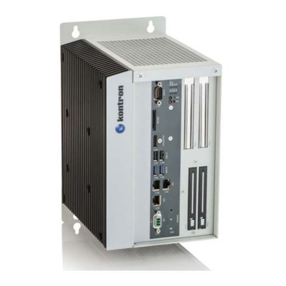
Page 16: System Overview
KBox C-101 – User’s Guide (Version 2.00) 7. System Overview The KBox C-101 System is a highly scalable and flexible industrial automation process monitor and control system. As such, it is designed to provide application process visualization and supervisory interaction capability. Performance scalability is achieved through the use of various Kontron COM Express®... -
Page 17: Rtc
The KBox C-101 comprises a chipset external RTC. This RTC is connected to the SMBus of the processor module. A RTC of type RV-8564 or compatible is used. To provide a valid date and time when no power is connected to the KBox C-101, the RTC is equipped with a goldcap buffer. -
Page 18: Setting The Rtc
There are two Mini PCIe interfaces on the KBox C-101 baseboard. One Mini PCIe interface connector is accessible from the top of the KBox C-101 when the top panel is removed. The other Mini PCIe interface connector is located on the bottom site of the baseboard and is not accessible in the field. -
Page 19: Fig. 3: Bottom Side View
7. System Overview KBox C-101 – User’s Guide (Version 2.00) Fig. 3: Bottom side view Fig. 4: Right side view Fig. 5: Front side view config. Fig. 6: Front side view config. Fig. 7: Left side view with removable drives without removable drives Fig. -
Page 20: Front Side
7. System Overview KBox C-101 – User’s Guide (Version 2.00) 7.3. Front Side Fig. 10: KBox C-101 - front view (shown with removable drive bays) Side of KBox C-101 with cooling fins Top side cover with knurled screws www.kontron.com... -
Page 21: Fig. 11: Block Diagram - Kbox C-101
7. System Overview KBox C-101 – User’s Guide (Version 2.00) LEDs KBox C-101 PWR LED System SPI Flash EPROM Power Button RESCUE BIOS RSQ LED RESCUE Button CPLD X 203 CPU Options Temperatur Sensor via Adapter Module RS232/RS422 i5 / i7 / Celeron®... -
Page 22: X101 - Power Input Connector
KBox C-101 – User’s Guide (Version 2.00) 7.3.1. X101 - Power Input Connector The 3-pin connector (X101, Fig. 10) provides the power connection of the KBox C-101 to the appropriate DC main power supply. For pin assignments refer to the subsection 18.1.1. -
Page 23: Sdcard Slot
7.3.6. SDCARD Slot This slot, marked “SDCARD” is an SDHC/SDXC compliant interface realized using a standard SD card connector. It is accessible at the front side of the KBox C-101 (Fig. 10) and is located between the serial interface (RS232/X110) and DISPLAYPORT. -
Page 24: Power Button And Pwr Led
The unit is only completely disconnected from the DC mains, when the power is removed As soon as external power is applied to the main input power connector, X101, the KBox C-101 begins to operate (boots up and then starts the operating system and application where available). -
Page 25: Status And General Purpose Leds
7.3.10. Status and General Purpose LEDs After power is applied and the KBox C-101 performs the boot procedure the LEDs show the POST code. In case of a boot failure within the uEFI the last post code is displayed. When the boot phase is passed without errors, the LEDs change to their status and general purpose function. -
Page 26: Sata Drive Bays
(refer to Fig. 10 and Fig. 19) or two internal 2.5" SATA HDD. The internal HDDs/SSDs are not accessible from the outside. The two 2.5” removable drive bays (DRIVE 1 and DRIVE 2) are accessible from the front side (Fig. 10) of the KBox C-101. -
Page 27: Left And Right Side View
Fig. 24:Top side of the KBox C-101 system When powering on the KBox C-101, make sure that the air intake and exhaust openings are not obstructed. To provide sufficient heat dissipation for the cooling of the KBox C-101 platform, never cover the cooling fins of the chassis. -
Page 28: Rear Side View
Fig. 26: Rear side of the KBox C-101 system 7.6.1. Functional Earth Stud There is an M4 functional earth terminal on the lower mounting plate of the KBox C-101 (Fig. 26, pos. 6). This terminal may be connected as required. -
Page 29: Internal View
15 Upper mounting bracket with key holes The KBox C-101 provides two internal Mini PCIe slots. One of them you can see in Fig. 27, pos. 4. The second Mini PCIe slot is on the bottom of the baseboard and can be only at the factory fitted with an expansion card. -
Page 30: Integrated Come Module
Search for the name of the installed board. 7.7.2. mSATA Socket Depending on the system configuration ordered your KBox C-101 can be extended with up to two mSATA SSD. For installation/removing of the mSATA SSD refer to the subsection 10.2.3, “Installing an mSATA SSD”. -
Page 31: Expansion Slots For Pcie Mini Cards
“Installing/Removing the PCIe Mini Card”. 7.7.4. Expansion Slots for PCIe x4 Cards Depending on the system configuration ordered your KBox C-101 can be extended with up to two PCIe x4 cards (full- height, half-length form factor). For installation/removing of the PCIe x4cards (Fig. 27, pos. 6), please refer to the subsection 10.2.1 “Installing/Removing the PCIe Expansion Cards”. -
Page 32: Thermal Considerations
For applications where convection cooling is not sufficient, there is the possibility to use the optional fan tray (externally mounted to the KBox C-101). The optional fan tray extension allows the KBox C-101 to operate at higher ambient temperature conditions and provides a higher airflow through the chassis providing better cooling of the system internal components. -
Page 33: Third Party Components
8.6. Third Party Components When the KBox C-101 is extended and configured with third party components like PCIe extension cards and hard drives (HDD or SSD), it has to be taken into account that the air temperature inside the system is higher than the ambient temperature. -
Page 34: Installation Instructions
9. Installation Instructions 9.1. Instructions for Control Cabinet Mount Installation The KBox C-101 comes with attached wall mount brackets. The available mounting key holes of the wall mount brackets allow the unit attaching to a wall of a fire resistant enclosure. -
Page 35: Accessing Internal Components
Before installing/removing an add-on card, please pay attention to the following information: Please observe the “General Safety Instructions for IT-Equipment” provided with the system (refer to the chapter 4) and the installation instructions in this manual. The KBox C-101 system shall be mounted into a control cabinet. -
Page 36: Top Cover
KBox C-101 – User’s Guide (Version 2.00) 10.1. Top Cover When used as intended the KBox C-101 is to operate only in closed condition. Only when the right side cover is fixed with the screws (Fig. 22, pos. 2) and top cover is properly installed, secured with the knurled screws (Fig. -
Page 37: Opening And Closing The Kbox C-101
4. Pull the cover out a little bit, as shown in Fig. 30, to release the cover centering and fixing brackets. Fig. 30: This movment allow you to remove the centring and fixing bracket of the top cover (detail of the KBox C-101) 5. -
Page 38: Fig. 32: Kbox C-101 Without Top Cover - Removing The Rihgt Side Cover
6. For better accessibility of the internal PCIe slots, PCIe slot for Mini card and the mSATA SSD connectors you may also remove the right side cover of the KBox C-101 (Fig. 33). Loosen the externally accessible fastening screws that secure the right side cover (Fig. -
Page 39: Installing/Removing The Pcie Expansion Cards
1. Close all applications; shut down the system properly and disconnect the connection to the power source. Disconnect all peripherals. 2. To have access to the PCIe x4 slots you have to open the KBox C-101 as described in the subsection 10.2 “Opening and Closing the KBox C-101” (step 1-6). -
Page 40: Installing An Msata Ssd
To have access to the mSATA slots please proceed according to the steps described: 1. Open the device as described in the subsection 10.2 “Opening and Closing the KBox C-101” (step 1-6). 2. Locate the mSATA slots and the corresponding fixing bolts. (Fig. 33, pos. 7 and 8). -
Page 41: Control Cabinet Mounting
Your KBox C-101 is supplied with assembled mounting plates. The key holes of the upper and lower mounting plates (Fig. 26, pos. 1 and pos. 3) allow you to mount the KBox C-101 to a mounting side of the control cabinet in vertical position. -
Page 42: Dc Power Connection
KBox C-101 – User’s Guide (Version 2.00) 11.1. DC Power Connection The KBox C-101 is connected by a Phoenix connector to a DC power source via a DC power supply wiring (only the Phoenix power plug terminal is included). The KBox C-101 is delivered with a DC power plug terminal (3-pin Phoenix connector). For DC connection prepare the connecting wires using the supplied Phoenix plug terminal: PSC 1,5/ 3-F. -
Page 43: Starting Up
12.1. Connecting to DC Main Power Supply The DC input connector (Fig. 10 and Fig. 12 marked X101) is located on the front side of the KBox C-101. The KBox C-101 will be connected to a DC main power supply via the supplied Phoenix power plug terminal (see Fig. 36) and corresponding power wires (not included). -
Page 44: Power Off/On Procedure
As the KBox C-101 is equipped with an internal hold-up buffer, it can’t be switch off/on immediately. The buffer time depends on the power consumption and load on the KBox C-101 processor and peripherals. Therefore the following procedure must be observed. -
Page 45: Operating System And Hardware Component Drivers
Your system can be supplied optionally with a pre-installed operating system. If you have ordered your KBox C-101 with a pre-installed operating system, all drivers are installed in accordance with the system configuration ordered (optional hardware components). Your system is fully operational when you switch it on for the first time. -
Page 46: Maintenance And Cleaning
KBox C-101 – User’s Guide (Version 2.00) 13. Maintenance and Cleaning Equipment from Kontron requires only minimum servicing and maintenance for proper operation. For light soiling, clean the KBox C-101 with a dry cloth. Carefully remove dust from the surface of the cooling fins of the chassis using a clean, soft brush. -
Page 47: System Extensions
UPS (Uninterruptable Power Supply): an additional component connected to the KBox C-101 Fan Tray: an additional component connected to the KBox C-101 These components you have to order separately in order to extend your KBox C-101 at the factory. Example of system configuration, see below: Fig. -
Page 48: Serial Port Rs232/Rs422
14.3. DVI-D Interface Connector Your KBox C-101 can be extended with a DVI-D interface. The DVI-D port (Single Link) (Fig. 37, pos. 3) marked “DVI” supports digital connections. Digital devices can be connected directly to this interface of the KBox C-101. -
Page 49: Optional Kbox C-101 Version With Fan Tray
The fan is integrated in a user-friendly, replaceable fan tray (hot-swap). The fan tray is designed to be inserted into the fan tray slot (Fig. 39, pos. 6) on the bottom side of the KBox C-101. The fan tray simplifies the installation and removal of this component, even during operation. -
Page 50: Fan Tray
To replace fan tray, proceed as follows: 1. Ensure to have access to the bottom side of the KBox C-101. The fan tray (Fig. 41, pos. 1) and (Fig. 42, pos. 2) may be replaced without removing the air filter holder (Fig. 41, pos. 4). -
Page 51: Cleaning The Air Filter
Fig. 41: Detail KBox C-101 with fan tray extension: air filter holder on the bottom side To replace the air filter, proceed as follows: 1. Ensure to have access to the bottom side of the KBox C-101. The air filter may be replaced without removing the fan tray (Fig. 41, pos. 1). -
Page 52: Fig. 42: Kbox C-101 With Removed Fan Tray And Removed Air Filter
Fig. 44: Holder with air filter Fig. 45: Air filter Legend for Fig. 42 and Fig. 43: 1 KBox C-101 assembled with the optional fan tray slot 6 Removed air filter 2 Removed fan tray 7 Air filter holder with knurled screw... -
Page 53: Uefi Bios
The Kontron uEFI BIOS features a built-in and enhanced version of the uEFI Shell. For a detailed description of the available standard shell scripting refer to the EFI Shell User’s Guide. For a detailed description of the available standard shell commands, refer to the EFI Shell Command Manual. -
Page 54: Kontron-Specific Uefi Shell Commands
It searches for scripts and executes them in the following order: 1. Kontron flash-stored startup script. 2. If there is no Kontron flash-stored startup script present, the uEFI-specified startup.nsh script is used. This script must be located on the root of any of the attached FAT formatted disk drive. -
Page 55: Create A Startup Script
15. uEFI BIOS KBox C-101 – User’s Guide (Version 2.00) 15.2.2. Create a Startup Script Startup scripts can be created using the uEFI Shell built-in editor edit or under any OS with a plain text editor of your choice. To create a startup shell script, simply save the script on the root of any FAT-formatted drive attached to the system. -
Page 56: Updating The Uefi Bios
15. uEFI BIOS KBox C-101 – User’s Guide (Version 2.00) Handling the Startup Script in the SPI Boot Flash 15.2.3.4. In case there is no mass storage device attached, the startup script can be generated in a RAM disk and stored in the SPI boot flash using the following instructions: 1. -
Page 57: Technical Specification
16. Technical Specification KBox C-101 – User’s Guide (Version 2.00) 16. Technical Specification KBox C-101 Installed COM Express Module and Baseboard with COMe-bHL6 i5-4402E or Baseboard with COMe-bHL6 i7-4700EQ or Baseboard Baseboard with COMe-bHL6 Celeron® 2002E i5-4402E: Dual-Core 1.6 GHz, 3MB cache, 37W max. power consumption, Processor i7-4700EQ: Quad-Core 2.4 GHz, 6MB cache, 47W max. -
Page 58: Mechanical Specifications Of The Kbox C-101
16. Technical Specification KBox C-101 – User’s Guide (Version 2.00) 16.1. Mechanical Specifications of the KBox C-101 Fig. 46:Dimensions: right side Fig. 47: Dimensions: front side with key holes Fig. 48:Dimensions: detail key hole Fig. 49: Dimensions: top side www.kontron.com... -
Page 59: Mechanical Specifications Of The Kbox C-101 With Fan Tray Option
16. Technical Specification KBox C-101 – User’s Guide (Version 2.00) 16.2. Mechanical Specifications of the KBox C-101 with Fan Tray Option Fig. 50:Dimensions: right side (with fan tray option) Fig. 51: Dimensions: front side with key holes (with fan tray option) Fig. -
Page 60: Environmental Specifications
16. Technical Specification KBox C-101 – User’s Guide (Version 2.00) Dimensions KBox C-101 (Standard Version) KBox C-101 (with optional Fan Tray) Height with mounting plates: 290 mm (11.42") with mounting plates: 324 mm (12.756") Width 155 mm (6.10") 155 mm (6.10") Depth with mounting plates: 210 mm (8.26 ") -
Page 61: Ce-Directives And Standards
16. Technical Specification KBox C-101 – User’s Guide (Version 2.00) 16.4. CE-Directives and Standards CE Directive Elektrical Safety General Product Safety Directive (GPSD) 2001/95/EC Low Voltage Directive (LVD) 2006/95/EC Electromagnetic EMC Directive 2004/108/EC Compatibility (EMC) CE Marking CE Directive 93/68/EEC... -
Page 62: Kbox C-101 Cpld Specific Registers
17. KBox C-101 CPLD Specific Registers KBox C-101 – User’s Guide (Version 2.00) 17. KBox C-101 CPLD Specific Registers ADDRESS REGISTER NAME 0x103 Reset Status Register (RSTAT) 0x107 Interrupt Status Register (INTSTAT) 0x108 Shutdown Control Register (SHDN_CTRL) 0x10A SPI Flash Control Register (SPIFCTRL) -
Page 63: Interrupt Status Register (Intstat)
17. KBox C-101 CPLD Specific Registers KBox C-101 – User’s Guide (Version 2.00) 17.2. Interrupt Status Register (INTSTAT) Address 0x107 Name PWR_BUT Reserved SDRQINT_0 Access Reset BITFIELD DESCRIPTION Power Button state: PWR_BUT 0 = Power Button released 1 = Power Button pressed... -
Page 64: Spi Flash Control Registers (Spifctrl)
17. KBox C-101 CPLD Specific Registers KBox C-101 – User’s Guide (Version 2.00) 17.4. SPI Flash Control Registers (SPIFCTRL) Address 0x10A Name Reserved SPIFORBU Res. Access Reset BITFIELD DESCRIPTION Force use of backup SPI Flash: SPIFORBU 0 = Normal operation (use COMe Flash) 1 = Force BIOS_DISx# to select carrier on-board SPI Flash 17.5. -
Page 65: Standard Interfaces - Pin Assignments
18. Standard Interfaces – Pin Assignments KBox C-101 – User’s Guide (Version 2.00) 18. Standard Interfaces – Pin Assignments Low-active signals are indicated by a minus sign. 18.1.1. (X 101) Power Input Connector Pin Signal Name 3-pin POWER SUBCON (male) -
Page 66: Displayport
18. Standard Interfaces – Pin Assignments KBox C-101 – User’s Guide (Version 2.00) 18.1.3. DisplayPort Pin# Signal Name DisplayPort Signal Name Pin# ML Lane 0 (p) GND (ML Lane 0) ML Lane 0 (n) Lane 1 (p) GND (ML Lane 1) -
Page 67: 102, X 103, X 104) Ethernet Connectors
18. Standard Interfaces – Pin Assignments KBox C-101 – User’s Guide (Version 2.00) 18.1.6. (X 102, X 103, X 104) Ethernet Connectors Pin# Signal Name 3x ETH (RJ45 female) MDI0+ MDI0- MDI1+ MDI2+ MDI2- MDI1- MDI3+ MDI3- LINK/ACT Speed (Mbps) -
Page 68: Optional Interfaces Via Adapter Modules
18. Standard Interfaces – Pin Assignments KBox C-101 – User’s Guide (Version 2.00) 18.2. Optional Interfaces via Adapter Modules 18.2.1. DVI-D (Single Link) Signal Name Description DVI-D Connector (female) TMDS2– Differential TMDS Data 2– TMDS2+ Differential TMDS Data 2+ TMDS Shield 4–5... -
Page 69: Serial Port Rs232/Rs422
18.2.2. Serial Port RS232/RS422 This port must be factory installed and configured only. When you order the KBox C-101 with this extended interface via RS232/422 adapter module, you have to specify in your ordering: the needed configuration of this port as RS232 or RS422 and for RS422 configuration: if the onboard termination resistor (120Ω) should be enabled or... -
Page 70: Can Bus Port
18. Standard Interfaces – Pin Assignments KBox C-101 – User’s Guide (Version 2.00) 18.2.3. CAN Bus Port If termination resistor (120Ω) is required, you have to make a connection (bridge) between pin 1 and 2, in order to enable the onboard termination resistor (120Ω). -
Page 71: Technical Support
Be ready to explain the nature of your problem to the service technician. If you have questions about Kontron or our products and services, you can reach us by the above-mentioned telephone number and on e-mail address or at: www.kontron.com...
Need help?
Do you have a question about the KBox C-101 and is the answer not in the manual?
Questions and answers