Table of Contents
Advertisement
Quick Links
Advertisement
Table of Contents

Related Manuals for Kontron KISS 4U V3 SKX


Summary of Contents for Kontron KISS 4U V3 SKX
- Page 1 USER GUIDE KISS 4U V3 SKX Doc. Preliminary Rev. 0.6 Doc. ID: 1065-2473...
- Page 2 KISS 4U V3 SKX – Preliminary Rev. 0.6 This page has been intentionally left blank www.kontron.com // 2...
- Page 3 In cases of doubt, contact Kontron. This user guide is protected by copyright. All rights are reserved by Kontron. No part of this document may be reproduced, transmitted, transcribed, stored in a retrieval system, or translated into any language or computer language, in any form or by any means (electronic, mechanical, photocopying, recording, or otherwise), without the express written permission of Kontron.
- Page 4 SEVERE PHYSICAL OR ENVIRONMENTAL DAMAGE (COLLECTIVELY "HIGH RISK APPLICATIONS"). You understand and agree that your use of Kontron products as a component in High Risk Applications is entirely at your own risk. To minimize the risks associated with your systems and applications, you must provide adequate design and operating safeguards.
- Page 5 If you have any difficulties using this user guide, discover an error, or just want to provide some feedback, contact Kontron support. Detail any errors you find. We will correct the errors or problems as soon as possible and post the revised user guide on our website.
-
Page 6: Symbols
KISS 4U V3 SKX – Preliminary Rev. 0.6 Symbols The following symbols may be used in this user guide: DANGER indicates a hazardous situation which, if not avoided, will result in death or serious injury. WARNING indicates a hazardous situation which, if not avoided, could result in death or serious injury. -
Page 7: For Your Safety
Therefore, in the interest of your own safety and of the correct operation of your new Kontron product, you are requested to conform with the following guidelines. -
Page 8: Lithium Battery Precautions
General Instructions on Usage In order to maintain Kontron’s product warranty, this product must not be altered or modified in any way. Changes or modifications to the product, that are not explicitly approved by Kontron and described in this user guide or received from Kontron Support as a special handling instruction, will void your warranty. -
Page 9: Table Of Contents
4.1.7. Filter Pad and Filter Pad Holder ............................... 25 4.1.8. Drive Bays ....................................... 26 4.2. Rear Side ........................................27 4.2.1. External Interface Panel KISS 4U V3 SKX ............................28 4.2.2. Power Supply Unit (PSU) ................................... 30 4.2.3. Potential Equalization Stud ................................30 4.2.4. - Page 10 KISS 4U V3 SKX – Preliminary Rev. 0.6 5.3.2. Network Card ......................................37 Thermal Considerations .................................. 38 6.1. Active Cooling ......................................38 6.2. Minimum System Clearance ................................38 6.3. Third Party Components ..................................38 Assembly ......................................39 7.1. Opening and Closing the Cover ................................39 7.2.
-
Page 11: List Of Tables
Figure 30: Step to Remove the Card Hold Down Brackets ......................... 42 Figure 31: Front Access Panel Side-plate and Handle Bracket ......................45 Figure 32: Slide Rail (inner part) on a KISS 4U V3 SKX ......................... 48 Figure 33: Slide Rail in the Pulled-out Position ............................. 48 Figure 34: Slide Rail in the Pushed-in Position ............................ - Page 12 KISS 4U V3 SKX – Preliminary Rev. 0.6 Figure 37: Fan Assembly without Filter Pad Holder ..........................53 Figure 38: Filter Pad Holder without Filter Pad ............................. 53 Figure 39: Filter Pad Holder with Filter Pad ............................53 Figure 40: Filter Pad......................................53 Figure 41: Removing the Fan Assembly ..............................
-
Page 13: 1/ General Safety Instructions For It Equipment
Instructions for IT Equipment are not observed, it could lead to injuries to the operator and/or damage to the product. Kontron is exempt from accident liability, also during the warranty period if the instructions within this user guide are not observed. - Page 14 KISS 4U V3 SKX – Preliminary Rev. 0.6 Additional safety instructions for DC power supply circuits To guarantee safe operation of products with DC power supply voltages larger than 60 volts DC or a power consumption larger than 120 VA, observe that: ...
-
Page 15: Operation Of Laser Source Devices
KISS 4U V3 SKX – Preliminary Rev. 0.6 1.1. Operation of Laser Source Devices Laser! Risk of exposure to laser beam and light emitting devices (LEDs) from DVD • Do not open DVD drive due to invisible laser radiation •... -
Page 16: Instructions For The Optional Lithium Battery
KISS 4U V3 SKX – Preliminary Rev. 0.6 1.3. Instructions for the optional Lithium Battery When replacing the mainboard’s battery, observe the instructions described in Chapter 10.3 Replacing the Lithium Battery. Danger of explosion when replacing with wrong type of battery Replace only with the same or equivalent type recommended by the manufacturer. -
Page 17: 2/ Introduction
KISS 4U V3 SKX – Preliminary Rev. 0.6 2/ Introduction This user guide focuses on describing the special features of the KISS 4U V3 SKX made by Kontron. New users are recommended to study the instructions within this user guide before switching on the power. -
Page 18: 3/ Scope Of Delivery
1065-0203 Front panel key 3.2. Shipment, Packaging and Unpacking The KISS 4U V3 SKX is packed together with all standard parts in a product specific cardboard packaging with suitable shock absorbers inside. 3.3. Type Label and Product Identification The type label with product name, serial number and technical data is located on the system. -
Page 19: 4/ Product Description
KISS 4U V3 SKX – Preliminary Rev. 0.6 4/ Product Description The KISS 4U V3 SKX platform expands the Kontron KISS computer line. KISS 4U V3 SKX is a scalable 4U (19") platform, equipped with a mainboard, supporting various system configurations. The flexible customer-specific hardware system configuration and the robust construction with excellent mechanical stability offers the superior qualities of a computer designed for operation in harsh industrial environment. - Page 20 The KISS 4U V3 SKX is powered with a 800 W Power Supply Unit (PSU) with an input voltage range of 100 V to 240 V. The power button is located on the front side behind the front access panel. The LED indicators are located on the front side and consist of a power, hard disk activity, LAN activity, system status and system ID LEDs Three system fans are installed at the front side of the system.
-
Page 21: Front Side
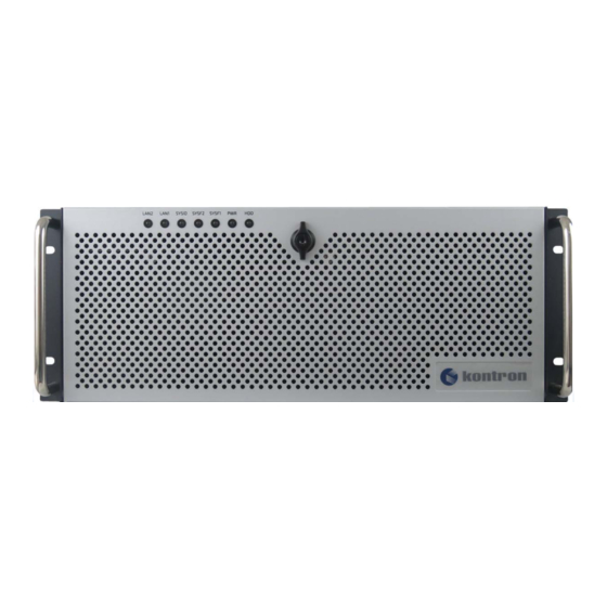
KISS 4U V3 SKX – Preliminary Rev. 0.6 4.1. Front Side The front side consists of two handle brackets for installation in a 19” Industrial rack and a front access panel with two front access panel side-plates attached via the handle brackets. -
Page 22: Figure 10: Front Side With Front Access Panel Opened
The power button, LED indicators, two USB ports, filter pad holder and the integrated drives are located at the front side of the KISS 4U V3 SKX platform behind the front access panel. Figure 10: Front Side with Front Access Panel Opened... -
Page 23: Power Button
Switching off the power using the front panel power button or the PSU’s power On/Off switch may not disconnect the KISS 4U V3 SKX platform from the main power source. A standby-voltage of 5 VSB may remain. The KISS 4V V3 SKX is only completely disconnected from the main power source, when the power cable is disconnected, either from the mains power plug socket, or the PSU’S AC power cable connector Therefore, for safety reasons the... -
Page 24: Led Indicators
KISS 4U V3 SKX – Preliminary Rev. 0.6 4.1.3. LED Indicators The LED indicators are located at the front side behind the front access panel. The LED status is also visible when the front access panel is closed. Figure 14: LED Indicators... -
Page 25: Front Access Panel
Table 1: Scope of Delivery. The secure locking mechanism enables users, to protect the KISS 4U V3 SKX platform from unauthorized use. Locking the front access panel means that the cover cannot be removed, and the drives, filter pad holder and power button are not accessible. -
Page 26: Drive Bays
KISS 4U V3 SKX – Preliminary Rev. 0.6 4.1.8. Drive Bays The drive bay can be a mixture of front accessible and internal drives, with a maximum of eight drives. The drive bays D1, D2 and D3 are accessible on the front panel or internally accessible. D1 and D2 drive bay can be fitted with removable, fixed or internal drives and may be used in combination to implement a three-drive solution. -
Page 27: Rear Side
KISS 4U V3 SKX – Preliminary Rev. 0.6 4.2. Rear Side The rear side consists of the mainboards interface panel, PSU and PCI expansion slots. For technical mainboard information, see Chapter 11.2: Technical Specification. Figure 16: Rear Side PSU power On/Off switch... -
Page 28: External Interface Panel Kiss 4U V3 Skx
11 Optical S/PDIF OUT port 6 1x USB 2.0 port USB 3.1 Gen 1 and Gen 2 data transfer rates differ. For optimum performance Kontron recommends using USB devices that match the USB ports transfer rate. USB 3.1 Gen 1/Gen 2 devices can be used as data storage only 4.2.1.1. - Page 29 The S/PDIF output is a digital audio optical output. S/PDIF enables high-quality audio signals by transferring the audio signal digitally from device to device, thus maintaining signal quality as no conversion to an analogue signal is required before transfer. To achieve high quality data transfer, Kontron recommends the use of optical cables. www.kontron.com // 29...
-
Page 30: Power Supply Unit (Psu)
4.2.2. Power Supply Unit (PSU) The PSU is located on the rear side of the KISS 4U V3 SKX platform. The PSU supports 860 W with a nominal voltage range of 100 V to 240 V. The PSU supplies the required internal voltages using standard certified cabling. The systems type label (Figure 1) indicates the required electrical data. -
Page 31: Pcie Slot Brackets
KISS 4U V3 SKX – Preliminary Rev. 0.6 4.2.4. PCIe Slot Brackets The PCIe slot brackets on the system’s rear side supports the installation of up to seven PCIe expansion cards. The slots brackets include ventilation holes and can be removed to install a PCIe expansion card by releasing an internal screw at the top of the slot bracket. -
Page 32: Sides (Left And Right)
4.3. Sides (Left and Right) On the left side and right side of the KISS 4U V3 SKX platform, are six M4 threaded screw holes (Figure 20 and Figure 21, pos. 2) used to install 19" industrial rack slide rails. -
Page 33: Cover
Activities such as work inside the system, system expansion with expansion cards, or maintenance must be performed by qualified personnel aware of the associated dangers!. The KISS 4U V3 SKX’s is only properly closed if the cover is attached and the cover’s knurled screws are securely fastened: •... -
Page 34: Internal View
KISS 4U V3 SKX – Preliminary Rev. 0.6 4.5. Internal View Figure 23: Internal View (slot 7) (slot 1) Drive bay 4 (D4) (internal only) 9 Expansion card (slots 1 to slot 7) and fastening screw 2 Drive bay cage including Drive bays D1, D2 and D3... -
Page 35: Bottom Side View (Tower Variant)
Feet, in the positions shown in Figure 24. When the KISS 4U V3 SKX tower is upright, the three system fans must be located in the lower part and the drive bays in the upper part of the KISS 4U V3 SKX tower. For more information, see Chapter 8.7: Installing as a Tower Attach the four rubber feet close to the four corners of the underside of the tower to improve the tower’s stability. -
Page 36: 5/ System Expansion
KISS 4U V3 SKX – Preliminary Rev. 0.6 5/ System Expansion Before expanding the KISS 4U V3 SKX platform, observe the instructions and guideline within this chapter. When expanding a system, do not exceed PSU specified maximum power consumption. 5.1. System Memory The system memory consists of up to 12x DIMM using DDR4 2400 RDIMMs, with six DIMMs per CPU/six channels.per... -
Page 37: Pcie Slots
5.3. PCIe Slots The KISS 4U V3 SKX platform supports up to seven PCIe 3.0 expansion cards using the rear side PCIe slots. For information on the possible PCIe expansion card types, see Table 5. The slots numbering is shown in Figure 23, pos.9. -
Page 38: 6/ Thermal Considerations
6.1. Active Cooling The KISS 4U V3 SKX platform is forced air-cooled using a fan assembly with three system fans that force air to flow from the air-intake ventilation holes on the front side to the air outlet ventilation holes on the rear side. The three system fans are controlled by its own internal temperature sensor. -
Page 39: 7/ Assembly
To access, internal components open the cover. Energy hazards-240 VA present inside the chassis! Before removing the KISS 4U V3 SKX’s cover, ensure that the system is switched off and disconnected from the mains power supply. Activities such as work inside the system, system expansion with expansion cards, or... -
Page 40: Figure 27: Releasing The Cover
Figure 28: Removing the Cover To close and secure the cover, proceed in the reverse order (step 5 to step 2). The KISS 4U V3 SKX is only properly closed when the cover is attached properly and the cover’s knurled screws fastened: •... -
Page 41: Accessing Internal Components
Energy hazards-240 VA present inside the chassis! Before removing the KISS 4U V3 SKX’s cover, ensure that: the system is switched off and disconnected from the mains power supply. Activities such as work inside the system, system expansion with expansion cards, or... -
Page 42: Figure 30: Step To Remove The Card Hold Down Brackets
KISS 4U V3 SKX – Preliminary Rev. 0.6 To install short expansion cards (half length), only the card hold down bracket for short expansion cards must be removed. Figure 30: Step to Remove the Card Hold Down Brackets Loosen the internal fastening screw (Figure 30, step 1) and then the externally accessible fastening screw (Figure 30, step 2) that secure the short card hold down bracket. - Page 43 Close the KISS 4U V3 SKX platform and secure the cover with the captive knurled screws. The KISS 4U V3 SKX’s is only properly closed if the cover is attached and all knurled screws are securely fastened: •...
-
Page 44: 8/ Installation
KISS 4U V3 SKX – Preliminary Rev. 0.6 8/ Installation Before installing or removing the KISS 4U V3 SKX in a 19” industrial rack or desktop environment, read the general installation instructions within this chapter. Read and observe the information in Chapter 1/:General Safety Instruction for IT Equipment. -
Page 45: Removing The Handle Brackets
Remove the handle bracket and store with the screws retained in step 1. To reinstall the handle brackets proceed in the reverse order. The KISS 4U V3 SKX platform is delivered with the handle brackets already assembled. 8.3. Removing the Front Access Panel and Front Access Panel Side-Plates The front access panel and the two front access panel side-plates are removable. -
Page 46: Installing As A Desktop
8.5. Installing in a 19" Industrial Rack Before installing the KISS 4U V3 SKX platform in a 19" industrial rack, observe the instructions described in this chapter and any additional safety warnings. To assemble for a 19” industrial rack using slide rails, see Chapter 8.6: Installing Slide Rails (Option). -
Page 47: Installing Slide Rails (Option)
Verify that the KISS 4U V3 SKX is securely mounted. 8.6. Installing Slide Rails (Option) Kontron offers compatible 19” Slide Rails and Rack Slide Rails Kit for the KISS 4U V3 SKX. For more information, see Table 2: Accessories and Spares Parts. -
Page 48: Figure 32: Slide Rail (Inner Part) On A Kiss 4U V3 Skx
KISS 4U V3 SKX – Preliminary Rev. 0.6 Figure 32: Slide Rail (inner part) on a KISS 4U V3 SKX Figure 33: Slide Rail in the Pulled-out Position Figure 34: Slide Rail in the Pushed-in Position Side view of the KISS 4U V3 SKX... -
Page 49: Installing As A Tower
Stand the system upright with the fan assemble in the lower part and the drive bays in the upper part of the front side. When operating the KISS 4U V3 SKX as a tower, the fan assembly including the three system fans must be located in the lower part and the drives in the upper part of the front side. -
Page 50: 9/ Starting Up
9.1. Connecting the Power Connection The AC mains input socket is located on the rear side of the KISS 4U V3 SKX. Power cable and power connectors must always remain easily accessible. -
Page 51: Loss Of Ac Power
[Last State] the system uses the last state before the AC power loss 9.2. Operating System (OS) and Hardware Components Drivers The KISS 4U V3 SKX is operational when switched on for the first time with a pre- installed OS and with all required drivers. Drivers are available from Kontron’s Customer Section. -
Page 52: 10/ Maintenance And Prevention
If heavily soiled, the filter pad can cause excessive heating of the system. Kontron recommends cleaning the filter pad when soiled. How often the filter pad needs to be cleaned depends on level of pollution in the operating environment. The filter pad can be changed during operation. -
Page 53: Figure 37: Fan Assembly Without Filter Pad Holder
Fasten the filter pad holder by tightening the knurled screw (Figure 36, pos. 2) to the bolt with tapped hole (Figure 37, pos. 1) on the fan assembly. Defective components may only be replaced by Kontron original spare parts. For a list of spare parts, see Table 2: Accessories and Spares Parts... -
Page 54: Replacing The Fan Assembly
Before replacing the fan assembly, read the following instructions: Operate the KISS 4U V3 SKX only with a functional fan assembly! Replace a defective fan assemble only with Kontron’s original fan assembly. see Table 2: Accessories and Spares Parts. Fan assembly replaceable during operation. -
Page 55: Figure 43: Fan Assembly Front Side
KISS 4U V3 SKX – Preliminary Rev. 0.6 Figure 43: Fan Assembly Front Side Figure 44: Fan Assembly Rear Side Fan assembly with two knurled screws 5 Positioning plate of the fan assembly 2 Connector for fan control 6 Fan s assembly housing 3 3x fans Reverse side of (Figure 43, pos. -
Page 56: Replacing The Lithium Battery
Place a new lithium battery in the battery holder and pay close attention to the polarity of the battery. Replaced the lithium battery only with the same type of battery or with a Kontron recommended battery. Reinstall the removed expansion cards and reattach the connecting cables, Close the cover, as described in the Chapter 7.1: Opening and Closing the Cover.(step 6) -
Page 57: 11/ Technical Data
KISS 4U V3 SKX – Preliminary Rev. 0.6 11/ Technical Data 11.1. Block Diagram Figure 45: Block Diagram KISS4U V3 SKX www.kontron.com // 57... -
Page 58: Technical Specification
KISS 4U V3 SKX – Preliminary Rev. 0.6 11.2. Technical Specification Table 6: Technical Specification Mainbaord WS C621E SAGE WS C621E SAGE (BMC) Dual lntel® Xeon® scalable processors: Processor Type Xeon® Gold 5119T Xeon® Silver 4116T Xeon® Silver 4114T ... - Page 59 KISS 4U V3 SKX – Preliminary Rev. 0.6 Front AccessibleDrive Options Drive Bay 1 1x 3.5" HDD 2 TB, 4 TB, 6 TB fixed or removable 2x 3.5”HDD 2 TB, 4 TB, 6 TB removable Occupying Bay 1 &2 / RAID 3x 3.5”...
-
Page 60: Mechanical Specification
KISS 4U V3 SKX – Preliminary Rev. 0.6 11.3. Mechanical Specification Table 7: Mechanical Specification Dimension KISS 4U V3 SKX KISS 4U V3 SKX (with front panel &handle brackets) (without front panel & handle brackets) Height (4U) 177 mm (6.97””) 177 mm (6.97”) -
Page 61: Directives And Standards
Kontron. The correction of interference caused by such unauthorized modification, substitution or attachment will be the responsibility of the user. The KISS 4U V3 SKX platform plans to comply with the following directives and standards: Table 9: Directives and Standards... -
Page 62: 12/ Standard Interfaces - Pin Assignments
KISS 4U V3 SKX – Preliminary Rev. 0.6 Standard Interfaces – Pin Assignments Low-active signals are indicated by a minus sign. 12.1. PS/2 Keyboard Mouse Connector The PS/2 connector is a combined keyboard or mouse connector. Signal Name 6-pin mini-DIN (female) Connector Keyboard/Mouse Data N.C. -
Page 63: Usb 3.1 Gen 2 (Type C) Port
KISS 4U V3 SKX – Preliminary Rev. 0.6 12.4. USB 3.1 Gen 2 (Type C) Port Signal Name Signal Name 24-pin USB 3.1 (Type C) Connector TX1+ RX1+ TX1- RX1- SBus Data+ Data- Data- Data+ SBU1 RX2- TX2- RX2+ TX2+ USB 3.1 Gen 1/Gen 2 devices can be used as data storage only... -
Page 64: Audio 8-Channel (2, 4, 5.1, Or 7.1 Channel Configurations)
The audio connectors outputs signals connect to the audio devices input signals and vice versa. 12.7. S/PDIF Port The S/PDIF is an digital audio optical output. To achieve high quality data transfer, Kontron recommends the use of optical cables. www.kontron.com // 64... -
Page 65: 13/ Bios
If the <DEL> key is not press the POST continues with the test routines The KISS 4U V3 SKX uEFI BIOS Setup program uses a hot key navigation system. The hot key legend bar is located at the bottom right corner of the Setup screens. For a list of the navigation hot keys available in the legend bar with a description, see Table 10: Navigation Hot Keys Available in the Legend Bar. -
Page 66: Bios Update
13.2. BIOS Update To ensure compatibility with new operating systems (OS), hardware or software and to integrate new BIOS functions Kontron recommends updating the BIOS. To update the BIOS easily use the available BIOS Flashback button and the USB Flashback port For information regarding available BIOS updates, visit https://www.asus.com/support/and enter the mainboard’s... - Page 67 KISS 4U V3 SKX – Preliminary Rev. 0.6 Rename the download file WSC621ES.CAP and copy the download file to the USB storage device inserted into the USB Flashback port. Press the Flashback button for at least 3 seconds until the BIOS Flash back LED blinks three times to indicate a successful BIOS update and wait until BIOS update is completed and the light goes out.
-
Page 68: 14/ Technical Support
RMA number. The buyer accepts responsibility for all freight charges for the return of goods to Kontron's designated facility. Kontron will pay the return freight charges back to the buyer's location in the event that the equipment is repaired or replaced within the stipulated warranty period. -
Page 69: 15/ Storage And Transportation
The storage facility must meet the products environmental storage requirements as stated within this user guide. Kontron recommends keeping the original packaging material for future storage or warranty shipments. -
Page 70: 16/ Warranty
16.1. Limitation/Exemption from Warranty Obligation In general, Kontron shall not be required to honor the warranty, even during the warranty period, and shall be exempted from the statutory accident liability obligations in the event of damage caused to the product due to failure to observe the following: ... -
Page 71: Appendix A: List Of Acronyms
KISS 4U V3 SKX – Preliminary Rev. 0.6 Appendix A: List of Acronyms Table 11: List of Acronyms Group Advanced Technology eXtended Power Supply Unit BIOS Basic Input Output System Random Access memory RDIMM Registered DIMM Command-Line Interface REACH Registration, Evaluation, Authorization... - Page 72 About Kontron Kontron is a global leader in embedded computing technology (ECT). As a part of technology group S&T, Kontron offers a combined portfolio of secure hardware, middleware and services for Internet of Things (IoT) and Industry 4.0 applications. With its standard products and tailor-made solutions based on highly reliable state-of-the-art embedded technologies, Kontron provides secure and innovative applications for a variety of industries.
Need help?
Do you have a question about the KISS 4U V3 SKX and is the answer not in the manual?
Questions and answers