Table of Contents
Advertisement
Quick Links
Advertisement
Table of Contents

Subscribe to Our Youtube Channel
Related Manuals for Kontron CB 752


Summary of Contents for Kontron CB 752
- Page 1 CB 752 User's Guide (Version 1.01) 0-0096-4743 If it’s embedded, it’s Kontron.
- Page 2 This page is intentionally left blank. www.kontron.com...
-
Page 3: Table Of Contents
8.1. Connecting to DC or AC Main Power Supply ....................23 8.1.1. Connecting the CB 752 Platform to a DC Main Power Supply..............23 8.1.2. Connecting the CB 752 Platform to an AC Main Power Supply using the AC/DC Adapter .........23 8.2. Operating Systems and Hardware Component Drivers ...................25 9. -
Page 4: Table Of Figures
Fig. 10: CB 752 –Controls and Indicators ......................12 Fig. 11: External Interfaces of the integrated SBC....................13 Fig. 12: CB 752 rear side with one (of two possible) WiFi antenna connector............16 Fig. 13: Covered USB port for system configuration with equipped COM3 port ............16 Fig. - Page 5 Fig. 20: DC power cord ..........................20 Fig. 21: AC/DC adapter ..........................20 Fig. 22: AC power cord ..........................20 Fig. 23: CB 752 with mounting brackets installed....................27 Fig. 24: Detail: Hanging holes........................27 Fig. 25: Left mounting bracket (optional) ....................... 27 Fig.
-
Page 6: Introduction
Kontron Embedded Computers is aware of such errors or inaccuracies or that Kontron Embedded Computers is unaware of these as a result of gross negligence and Kontron Embedded Computers has failed to eliminate these errors or inaccuracies for this reason. Kontron Embedded Computers expressly informs the user that this manual only contains a general description of technical processes and instructions which may not be applicable in every individual case. -
Page 7: Symbols Used In This Manual
2. Introduction CB 752 – User's Guide (Version 1.01) 2.1. Symbols used in this Manual Symbol Meaning This symbol indicates the danger of injury to the user or the risk of damage to the product if the corresponding warning notices are not observed. -
Page 8: Important Instructions
In the event of damage to the device caused by failure to observe the included document “General Safety Instructions for IT Equipment”, the hints in this manual or eventually the warning signs label on the device, Kontron Embedded Computers shall not be required to honor the warranty even during the warranty period and shall be exempted from the statutory accident liability obligation. -
Page 9: Safety Instructions
4. Safety Instructions CB 752 – User's Guide (Version 1.01) 4. Safety Instructions Please consider the included “General Safety Instructions for IT Equipment”. 4.1. Electrostatic Discharge (ESD) A sudden discharge of electrostatic electricity can destroy static-sensitive devices or micro-circuitry. Proper packaging and grounding techniques are necessary precautions to prevent damage. -
Page 10: Fcc Statement
4. Safety Instructions CB 752 – User's Guide (Version 1.01) 4.3. FCC Statement This equipment has been tested and found to comply with the limits for a Class A digital device, pursuant to Part 15 of the FCC Rules. These limits are designed to provide reasonable protection against harmful interference when the equipment is operated in commercial environment. -
Page 11: Scope Of Delivery
COM3 (RS232) via USB (for more information refer to “EASY USB to RS232” on www.kontron.com) CAN bus module 5.1. Type Label and Product Identification The type label (product name, serial number) and the inspection status label of your CB 752 system are located on the bottom side of the device. Fig. 1: Front view Fig. -
Page 12: Product Description
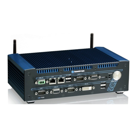
2.5" HDD (SATA or SSD) and/or a CompactFlash™ card, type I (see chapter 6.3 “Storage Media”). The CB 752 is a fanless system with a compact aluminum chassis with cooling fins. The rated voltage of the mains can be found on the type label. The type label is located at the bottom side of the device. The CB 752 can be factory-equipped with a Mini PCI express WLAN card for one or two antennas. -
Page 13: Front View
The device may be operated in all positions except with the upper side facing down. When switching on the CB 752, make sure that the air openings on the front side (Fig. 9, pos. 3) and the rear side (Fig. 12, pos. 2) and the cooling fins of the chassis are not obstructed (covered) by any objects. -
Page 14: Controls And Indicators
Therefore, the power cord and its connectors must always remain easily accessible. Power LED and HDD LED 6.1.2.2. The power LED (Fig. 10, pos. 2) and the HDD LED (Fig. 10, pos. 3) which are located on the front side of the CB 752 platform indicate the system status. System... -
Page 15: External Interfaces Of The Sbc Board At The Front Side
6. Product Description CB 752 – User's Guide (Version 1.01) RESET-Button 6.1.2.3. To restart the system, e. g. when the system is not responding, press the reset button (Fig. 10, pos. 1). During a reset, all Data in the main memory (RAM) will be erased. The system reboots without needing to switch the computer off and on again. -
Page 16: Optional Interfaces On The Front Side
USB port (Fig. 12, pos. 3) at the rear side is functional (refer to the section 6.2.2 “USB Ports”. The CB 752 system with equipped COM3 (Fig. 9, pos. 7) is delivered with mounted cover to the upper not functional USB port (Fig. 12, pos. 3). Do not remove this cover. - Page 17 6. Product Description CB 752 – User's Guide (Version 1.01) Optional CAN Bus interface 6.1.4.4. This interface (Fig. 9, pos. 5) can only be factory-configured to the customer's specifications. The installed LPC-to-CAN bus module provides a galvanic isolation of 500VDC.
-
Page 18: Rear Side
(Mic-In) can be connected. 6.2.2. USB Ports The CB 752 platform provides two USB2.0 ports on the rear side (Fig. 12, pos. 3). You can connect various USB devices to these USB 2.0 interface connectors. If you have ordered the CB 752 equipped with the additional serial interface COM3 (Fig. 9, pos. 7), please note that only the lower of the USB ports (Fig. -
Page 19: Wifi /Wlan (Option)
6.2.3.1. During the installation of the CB 752 system an antenna (not provided) (Fig. 14) will be screwed on to the RP SMA connector (Fig. 12, pos. 1). ). The antenna can be tilt and rotated in the appropriate position to get the optimal transmission and reception quality. -
Page 20: Chassis With Cooling Fins
Three sides of the aluminum chassis (left, upper and right side) are covered with cooling fins. The cooling fins provide heat dissipation during operation. To provide sufficient heat dissipation for the cooling of the CB 752 platform, never cover the cooling fins of the chassis. Do not place any objects onto the device. -
Page 21: Bottom Side
6. Product Description CB 752 – User's Guide (Version 1.01) 6.5. Bottom Side At the bottom side are located: the type label, the inspection status label and if applicable, the license sticker. Fig. 19: Bottom side 1 Knurled screws of the CF slot access... -
Page 22: Dc Power Cord
6. Product Description CB 752 – User's Guide (Version 1.01) 6.6. DC Power Cord Plus terminal Minus terminal DC-out connector Fig. 20: DC power cord 6.7. AC/DC-Adapter (Option) The external AC/DC adapter is provided with an AC power cord. AC/DC-Adapter... -
Page 23: Assembly, Disassembly
7. Assembly, Disassembly CB 752 – User's Guide (Version 1.01) 7. Assembly, Disassembly 7.1. Handling internal Components This chapter contains important information on working safely with internal components. Please follow these instructions when handling cards. When opening the device, always follow the descriptions in this manual. -
Page 24: Inserting And Removing The Cf Card
The on-board CompactFlash™ slot allows the operation of a CompactFlash™ card type I. The access cover of the CompactFlash™ slot is located at the rear side of your CB 752 platform. Before opening the CF card access cover to insert or to remove a CompactFlash™ card, the system must be switched off and disconnected from the main power supply. -
Page 25: Starting Up
To connect the CB 752 platform to a corresponding DC main power supply, please perform the following steps: 1. Connect the 3-pin connector of the DC power cord to the DC input connector (Fig. 9, Pos. 1) of the CB 752 platform. - Page 26 To connect the CB 752 platform to a corresponding AC main power supply, please perform the following steps: 1. Connect the 3-pin connector of the AC/DC adapter to the DC input connector (Fig. 9, pos. 1) of the CB 752 platform.
-
Page 27: Operating Systems And Hardware Component Drivers
(optional hardware components). Your system is fully operational when you switch it on for the first time. If you have ordered CB 752 without a pre-installed operating system, you will need to install the operating system and the appropriate drivers for the system configuration you have ordered (optional hardware components) yourself. -
Page 28: Installing The Cb 752 Platform
9.1. CB 752 Platform - Desktop The CB 752 platform will be delivered as desktop version with rubber feet attached to the bottom side of the device. When positioning the device, pay attention to the restriction range at the front and rear side of the platform. See chapter 11.2.1 “CB 752 Desktop Dimensions”. -
Page 29: Mounting Using The Brackets
Fig. 26) are available (see chapter 11.2.2 “Dimensions for Wall and Table Mounting”). It requires little effort to attach the mounting brackets to the bottom side of the CB 752 platform. Use the installed torx screws (Fig. 19, pos. 4). To do so, the rubber feet have to be removed first. -
Page 30: Maintenance And Prevention
10. Maintenance and Prevention CB 752 – User's Guide (Version 1.01) 10. Maintenance and Prevention Equipment from Kontron Embedded Computers requires only minimum servicing and maintenance for problem-free operation. For light soiling, clean the CB 752 with a dry cloth. -
Page 31: Protection Against Overheating
10. Maintenance and Prevention CB 752 – User's Guide (Version 1.01) Caution Danger of explosion when replacing with wrong type of battery. Replace only with the same or equivalent type recommended by the manufacturer. The lithium battery type must be UL recognized. -
Page 32: Technical Data
Mains Power Supply See type label Only CB 752 systems equipped with the optional COM3 are delivered with a mounted cover to the upper not functional USB port. Do not remove this cover. * The corresponding document “Configuration Guide” and the manual of the installed motherboard can be downloaded from our web site: www.kontron.com... -
Page 33: Electrical Specifications
11. Technical Data CB 752 – User's Guide (Version 1.01) 11.1. Electrical Specifications The corresponding electrical specifications for your CB 752 platform can be found on the type label of the system. 11.2. Mechanical Specifications 11.2.1. CB 752 Desktop Dimensions For a sufficient air circulation around the device, we recommend not to place (mount) or operate any other devices within the restriction area marked with “40mm”... -
Page 34: Fig. 30: Dimensions In The Rear View (Desktop)
11. Technical Data CB 752 – User's Guide (Version 1.01) Fig. 30: Dimensions in the rear view (desktop) Fig. 31: Dimensions in the bottom view (desktop) www.kontron.com... -
Page 35: Dimensions For Wall And Table Mounting
11. Technical Data CB 752 – User's Guide (Version 1.01) 11.2.2. Dimensions for Wall and Table Mounting For a sufficient air circulation around the device, we recommend not to place (mount) or operate any other devices within the restriction area marked with “40mm” (all around the cooling fins of the chassis) (see Fig. -
Page 36: Fig. 34: Dimensions In The Top View (Wall Or Table Mounting)
11. Technical Data CB 752 – User's Guide (Version 1.01) Fig. 34: Dimensions in the top view (wall or table mounting) Fig. 35: Dimensions in the rear view (wall or table mounting) www.kontron.com... -
Page 37: Environmental Specifications
11. Technical Data CB 752 – User's Guide (Version 1.01) 11.3. Environmental Specifications Operating Temperature / -15 … +60 °C, (+5 … +140 °F), not condensing (for system configuration with rotating storage media, e.g. with HDD) Relative Humidity -20 … +60 °C, (-4 … +140 °F), not condensing (for system configuration with non-rotating storage media, e.g. -
Page 38: Ec Directives And Standards
11. Technical Data CB 752 – User's Guide (Version 1.01) 11.4. EC Directives and Standards EC Directives Low voltage directive General Product Safety Directive (GPSD) 2001/95/EG (electrical safety) Low Voltage Directive (LVD) 2006/95/EG EMC directive EMC Directive 2004/108/EG EC marking... -
Page 39: Standard Ports - Pin Assignment
12. Standard Ports – Pin Assignment CB 752 – User's Guide (Version 1.01) 12. Standard Ports – Pin Assignment Low-active signals are identified with a minus sign. 12.1.1. DC IN Connector Signal Name 3-pin DC-In connector (male) 0V (input) +24 VDC (input) 12.1.2. -
Page 40: Serial Port Com2 (Rs422/Rs485) Configured As Rs422 (4-Channel Mode)
12. Standard Ports – Pin Assignment CB 752 – User's Guide (Version 1.01) 12.1.3. Serial Port COM2 (RS422/RS485) configured as RS422 (4-channel mode) Signal Name 9-pin D-SUB connector (female) TxD- (Transmit Data-) RxD+ (Receive Data+) TxD+ (Transmit Data+) RxD- (Receive Data-) -
Page 41: Serial Port Com2 (Rs422/Rs485) Configured As Rs485 (2-Wire Mode), Half Duplex
12. Standard Ports – Pin Assignment CB 752 – User's Guide (Version 1.01) 12.1.5. Serial Port COM2 (RS422/RS485) configured as RS485 (2-wire mode), half duplex Signal Name 9-pin D-SUB connector (female) Data (-) Data (+) (Signal Ground) 12.1.6. VGA Port... -
Page 42: Can Bus Connector
12. Standard Ports – Pin Assignment CB 752 – User's Guide (Version 1.01) 12.1.7. CAN Bus Connector For settings, please refer to chapter 6.1.4.4 “Optional CAN Bus interface”. Signal Name 9-pin D-SUB connector (male) CANL (galvanically separated) CAN0V (galvanically separated) CANH (galvanically separated) 12.1.8. -
Page 43: Technical Support
• the serial number (SN) of the unit (the serial number can be found on the type label, placed on the bottom side of the system). Be ready to explain the nature of your problem to the service technician. If you have questions about Kontron Embedded Computers or our products and services, you may reach us at the aforementioned numbers, or at: www.kontron.com...
Need help?
Do you have a question about the CB 752 and is the answer not in the manual?
Questions and answers