
Related Manuals for Kontron KBox A-201


Summary of Contents for Kontron KBox A-201
- Page 1 » User’s Guide « KBox A-201/A-202 User’s Guide (Version 1.2) 1059-4235 www.kontron.com...
- Page 2 0. Table of Contents KBox A-201/A-202 – User’s Guide (Version 1.2) This page has been intentionally left blank. www.kontron.com...
-
Page 3: Table Of Contents
5.6.5. Reset Button ..........................24 5.6.6. X201 – Serial Port COM 1 ........................ 24 5.6.7. X202 - Serial Port COM 2 (Option; KBox A-201 SMARC-sXQU only) ............24 5.6.8. X203 - Serial Port COM 3 (Option; KBox A-202 SMARC-sXBT only) ............. 24 5.7. - Page 4 10. Technical Specification ........................36 10.1. Mechanical Specifications ........................37 10.1.1. Mechanical Specifications of the KBox A-201/A-202 with DIN rail clip ............. 37 10.1.2. Mechanical Specifications of the KBox A-201/A-202 with Vertical Mounting Plate ........38 10.2. Environmental Specifications ....................... 39 10.3.
-
Page 5: Table Of Figures
Fig. 15: Keep out area for mounting around KBox A-201/A-202 (side view with optional antenna) ......30 Fig. 16: Keep out area for mounting around KBox A-201/A-202 (front view with vertical mounting bracket) ....31 Fig. 17: Phoenix power plug terminal ......................32 Fig. -
Page 6: Disclaimer
Kontron would like to point out that the information contained in this user guide may be subject to alteration, particularly as a result of the constant upgrading of Kontron products. This document does not entail any guarantee on the part of Kontron with respect to technical processes described in the user guide or any product characteristics set out in the user guide. - Page 7 (COLLECTIVELY, "HIGH RISK APPLICATIONS"). You understand and agree that your use of Kontron devices as a component in High Risk Applications is entirely at your risk. To minimize the risks associated with your products and applications, you should provide adequate design and operating safeguards.
-
Page 8: Terms And Conditions
Kontron warrants products in accordance with defined regional warranty periods. For more information about warranty compliance and conformity, and the warranty period in your region, visit http://www.kontron.com/terms-and-conditions. Kontron sells products worldwide and declares regional General Terms & Conditions of Sale, and Purchase Order Terms & Conditions. Visit http://www.kontron.com/terms-and-conditions. -
Page 9: Symbols Used In This Manual
This manual includes description and specifications for the KBox A-20x Family product line. Product Variants of the KBox A-200 Family Used Designation KBox A-201 Equipped with SMARC-sXQU processor module KBox A-202 Equipped with SMARC sXBTi processor module For the different KBox A-201/A-202 configurations refer also to chapter 10 “Technical Specification”. www.kontron.com... -
Page 10: For Your Safety
It was also designed for a long fault-free life. However, the life expectancy of your product can be drastically reduced by improper treatment during unpacking and installation. Therefore, in the interest of your own safety and of the correct operation of your new Kontron product, you are requested to conform with the following guidelines. -
Page 11: Disposal And Recycling
General Instructions on Usage In order to maintain Kontron’s product warranty, this product must not be altered or modified in any way. Changes or modifications to the product, that are not explicitly approved by Kontron and described in this user guide or received from Kontron Support as a special handling instruction, will void your warranty. -
Page 12: General Safety Instructions For It Equipment
If the following general safety instructions are not observed, it could lead to injuries to the operator and/or damage of the product; in cases of nonobservance of the instructions Kontron is exempt from accident liability, this also applies during the warranty period. -
Page 13: Electrostatic Discharge (Esd)
The devices do not generally fulfill the requirements for "centralized DC power systems“ (UL 60950-1, Annex NAB; D2) and therefore may not be connected to such devices! (The following section is not applicable for the KBox A-201/A-202) To guarantee safe operation of devices with DC power supply voltages larger than 60 volts DC or a power consumption larger than 240 VA), please observe that: •... -
Page 14: Electromagnetic Compatibility (Class A Device)
3. Electromagnetic Compatibility (Class A Device) KBox A-201/A-202 – User’s Guide (Version 1.2) 3. Electromagnetic Compatibility (Class A Device) 3.1. Electromagnetic Compatibility (EU) This product is intended only for use in industrial areas. The most recent version of the EMC guidelines (EMC Directive 2014/30/EU) and/or the German EMC laws apply. -
Page 15: Shipment And Unpacking
8. Please keep the associated paperwork. It contains important information for handling the unit. 9. Check the contents for visible shipping damage. 10. If you notice any shipping damage or inconsistencies between the contents and your order, please contact Kontron for help and information. -
Page 16: Type Label And Product Identification
KBox A-201/A-202 – User’s Guide (Version 1.2) 4.3. Type Label and Product Identification The type label (product name, serial number) of your KBox A-201/A-202 system is located on the bottom side of the device (refer to Fig. 1 and Fig. 8, pos. 1). -
Page 17: System Overview
KBox A-201/A-202 – User’s Guide (Version 1.2) 5. System Overview The KBox A-201/A-202 expands the Kontron line of computers - KBox Series. It is a highly scalable and flexible industrial computer. The scalability performance is achieved through the use of the Computer-on-Module SMARC-sXBT (KBox A-202) and SMARC-sXQU (KBox A-201). -
Page 18: Rtc
7.1 “System Mounting”. 5.1. RTC The KBox A-201/A-202 comprises a chipset internal RTC. To provide a valid date and time when no power is connected to the KBox A-201/A-202, the RTC is equipped with a goldcap buffer. -
Page 19: Block Diagrams
5. System Overview KBox A-201/A-202 – User’s Guide (Version 1.2) 5.3. Block Diagrams 5.3.1. Block diagram of KBox A-201 Fig. 2: Block diagram of KBox A-201 www.kontron.com... -
Page 20: Block Diagram Of Kbox A-202
5. System Overview KBox A-201/A-202 – User’s Guide (Version 1.2) 5.3.2. Block diagram of KBox A-202 Fig. 3: Block diagram of KBox A-202 www.kontron.com... -
Page 21: Front Side Of Kbox A-201
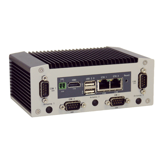
5. System Overview KBox A-201/A-202 – User’s Guide (Version 1.2) 5.4. Front Side of KBox A-201 Antenna 3 Reset button X106 X105 Antenna 2 X10³/X104 USB 2.0 X202 RS232 X101 24V DC Antenna 1 X201 RS232 Fig. 4: Front view of KBox A-201... -
Page 22: Front Side Of Kbox A-202
5. System Overview KBox A-201/A-202 – User’s Guide (Version 1.2) 5.5. Front Side of KBox A-202 Antenna 3 Reset button X203 X106 RS485 X105 Antenna 2 X10³/X104 USB 2.0 X10² HDMI X101 24V DC Antenna 1 X201 RS232 Fig. 5: Front view of KBox A-202... -
Page 23: Front Interfaces Of The Kbox A-20X
5.6. Front Interfaces of the KBox A-20x 5.6.1. X101 - Power Input Connector The 2-pin connector (X101, Fig. 4, Fig. 6) provides the power connection of the KBox A-201/A-202 to the appropriate DC main power supply. For pin assignments refer to the subsection 11.1.1. -
Page 24: Reset Button
KBox A-201/A-202 – User’s Guide (Version 1.2) 5.6.5. Reset Button If your system no longer reacts, you need to restart the KBox A-201/A-202 platform. Press the reset button to restart your system. Use a pointed object (e.g. a pencil) to press the recessed reset button. -
Page 25: Left And Right Side View
Fig. 11: Bottom side of the KBox A-201/A-202 system Fig. 10:Top side of the KBox A-201/A-202 system To provide sufficient heat dissipation for the cooling of the KBox A-201/A-202 platform, never cover the cooling fins of the chassis. Do not place any objects onto the device. -
Page 26: Rear Side View
5.9.1. Rear Side View of the KBox A-201/A-202 with Vertical Mounting Bracket The KBox A-201/A-202 is designed for wall mounting, in vertical position inside of a control cabinet. Please observe the mounting instructions included in the section 7 “Installation Instructions”, and the outline dimensions in the subsection 10.1.2 “Mechanical Specifications of the KBox A-201/A-202 with Vertical Mounting Plate”. -
Page 27: Optional Parts
5.10.1. DIN Rail Clip (Option) For DIN Rail mounting of the KBox A-201/A-202 a DIN Rail clip can be ordered (refer to subsection 4.2.2 “Optional Parts”). If ordered, you can adopt your system for mounting to a DIN Rail. Tapped holes are provided on the access cover (Fig. 8, pos. -
Page 28: Thermal Considerations
The applied cooling method provides adequate cooling of the device during operation and performs a one-way thermal transfer to the chassis. Three sides of the KBox A-201/A-202 consist of a compact aluminum chassis with cooling fins. The cooling fins provide heat dissipation during operation. -
Page 29: Installation Instructions
Refer also to section 10.1.2 “Mechanical Specifications”. The KBox A-201/A-202 must be firmly attached to a clean flat and solid mounting surface. Use proper fastening materials suitable for the mounting surface. Ensure that the mounting surface type and the used mounting solution safely support the load of the KBox A-201/A-202 and the attached components. -
Page 30: System Mounting
Depending on the ordered KBox A-201/A-202 configuration, your system is supplied with the corresponding mounting plate or DIN Rail clip. The key holes of the vertical mounting plate (Fig. 12, pos. 2) allow you to mount the KBox A-201/A-202 in vertical position. -
Page 31: Fig. 16: Keep Out Area For Mounting Around Kbox A-201/A-202 (Front View With Vertical Mounting Bracket)
7. Installation Instructions KBox A-201/A-202 – User’s Guide (Version 1.2) KEEP OUT AREA (air circulation) Fig. 16: Keep out area for mounting around KBox A-201/A-202 (front view with vertical mounting bracket) www.kontron.com... -
Page 32: Dc Power Connection
KBox A-201/A-202 – User’s Guide (Version 1.2) 7.2. DC Power Connection The KBox A-201/A-202 is connected by a Phoenix connector to a DC power source via a DC power supply wiring (only the Phoenix power plug terminal is included). The KBox A-201/A-202 is delivered with a DC power plug terminal (2-pin Phoenix FMC 1,5/ 2-ST-3,5 2-pin plug). For DC connection prepare the connecting wires using the supplied Phoenix plug terminal. -
Page 33: Starting Up
8.1. Connecting to DC Main Power Supply The DC input connector (Fig. 4 and Fig. 6, marked X101) is located on the front side of the KBox A-201/A-202. The KBox A-201/A-202 will be connected to a DC main power supply via the supplied Phoenix power plug terminal (see Fig. 17) and corresponding power wires (not included). -
Page 34: Connecting To The Kbox A-201'S Serial Console
Yocto Linux you will be able to login via this serial connection. In order to establish a serial connection, connect a serial null modem cable to the COM2 port of the KBox A-201 and to the corresponding RS-232 serial port of the host system. On the host system, an appropriate terminal application is required (i.e. -
Page 35: Maintenance And Cleaning
Equipment from Kontron requires only minimum servicing and maintenance for proper operation. For light soiling, clean the KBox A-201/A-202 with a dry cloth. Carefully remove dust from the surface of the cooling fins of the chassis using a clean, soft brush. -
Page 36: Technical Specification
10. Technical Specification KBox A-201/A-202 – User’s Guide (Version 1.2) 10. Technical Specification KBox A-201 KBox A-202 Installed CPU Module and Baseboard with SMARC-sXQUi module Baseboard with SMARC-sXBTi module Baseboard Processor Intel® Quark X1011 Intel® Atom E3845 1GB (soldered) 4GB (soldered) -
Page 37: Mechanical Specifications
Chassis: steel sheet, light grey (RAL 7035) Side with External Interfaces : trim strips, traffic grey (RAL 7043) 10.1.1. Mechanical Specifications of the KBox A-201/A-202 with DIN rail clip Fig. 20:Dimensions: front without vertical mounting plate Fig. 21: Dimensions: top side without vertical mounting brackets... -
Page 38: Mechanical Specifications Of The Kbox A-201/A-202 With Vertical Mounting Plate
10. Technical Specification KBox A-201/A-202 – User’s Guide (Version 1.2) 10.1.2. Mechanical Specifications of the KBox A-201/A-202 with Vertical Mounting Plate 99.5 Fig. 22:Dimensions: left side Fig. 23: Dimensions: rear side with vertical mounting plate Fig. 24:Dimensions: detail key hole... -
Page 39: Environmental Specifications
10. Technical Specification KBox A-201/A-202 – User’s Guide (Version 1.2) 10.2. Environmental Specifications KBox A-201 (Standard Version) KBox A-202 (Standard Version) Thermal Management Convection cooling Convection cooling Operating Temperature -40°C … +55°C (-40 … 131 °F) -40°C … +55°C (-40 … 131 °F) Storage / Transit Temperature -40 °C …... -
Page 40: Ce Directives And Standards
10. Technical Specification KBox A-201/A-202 – User’s Guide (Version 1.2) 10.3. CE Directives and Standards CE Directive Elektrical Safety General Product Safety Directive (GPSD) 2001/95/EC Low Voltage Directive (LVD) 2014/35/EU Electromagnetic EMC Directive 2014/30/EU, R&TTE Directive 2014/53/EU Compatibility (EMC) CE Marking... -
Page 41: Standard Interfaces - Pin Assignments
11. Standard Interfaces – Pin Assignments KBox A-201/A-202 – User’s Guide (Version 1.2) 11. Standard Interfaces – Pin Assignments Low-active signals are indicated by a minus sign. 11.1.1. (X101) Power Input Connector Pin Signal Name 2-pin POWER SUBCON (female) 0 V (Ground) +24 V DC (Input) 11.1.2. -
Page 42: X202) Serial Interface Com 2 (Rs232) Kbox A-201/ Smarc-Sxqu Only
11. Standard Interfaces – Pin Assignments KBox A-201/A-202 – User’s Guide (Version 1.2) 11.1.3. (X202) Serial interface COM 2 (RS232) KBox A-201/ SMARC-sXQU only Pin Signal Name 9-pin D-SUB Connector (male) N.C. COM2_RXD (Receive Data) COM2_TXD (Transmit Data) N.C. (Signal Ground) N.C. -
Page 43: 105 As Eth 1 And X 106 As Eth 2) Ethernet Connectors
11. Standard Interfaces – Pin Assignments KBox A-201/A-202 – User’s Guide (Version 1.2) 11.1.6. (X 105 as ETH 1 and X 106 as ETH 2) Ethernet Connectors Pin# Signal Name 2x ETH (RJ45 female) MDI0+ MDI0- MDI1+ MDI2+ MDI2- MDI1-... -
Page 44: X102) Hdmi Port
11. Standard Interfaces – Pin Assignments KBox A-201/A-202 – User’s Guide (Version 1.2) 11.1.7. (X102) HDMI Port Pin# Signal Name Description Type A full size HDMI connector TMDS data differential line 2+ TMDS Data 2+ Ground TMDS data differential line 2-... - Page 45 About Kontron Kontron is a global leader in embedded computing technology (ECT). As a part of technology group S&T, Kontron offers a combined portfolio of secure hardware, middleware and services for Internet of Things (IoT) and Industry 4.0 applications. With its standard products and tailor-made solutions based on highly reliable state-of-the-art embedded technologies, Kontron provides secure and innovative applications for a variety of industries.
Need help?
Do you have a question about the KBox A-201 and is the answer not in the manual?
Questions and answers