Table of Contents
Advertisement
Quick Links
Advertisement
Table of Contents

Subscribe to Our Youtube Channel
Related Manuals for Kontron 2-A0HC Series


Summary of Contents for Kontron 2-A0HC Series
- Page 2 This page intentionally left blank...
-
Page 3: Table Of Contents
1. Table of Contents 1. Table of Contents 1. Table of Contents ................................1 2. Introduction..................................3 2.1. Symbols used in this Manual ............................4 3. Important Instructions..............................5 3.1. Note on the Warranty..............................5 3.2. Exclusion of Accident Liability Obligation........................5 3.3. Liability Limitation / Exemption from the Warranty Obligation ..................5 4. - Page 4 1. Table of Contents 7.2. Environmental Specifications ............................. 41 7.3. Mechanical Specifications ............................42 7.3.1. Dimensions for M@CII 70/104/121/150 ......................42 7.4. CE Directives and Standards ............................. 46 8. Standard Interfaces - Pin Assignments........................47 8.1.1. Ethernet Interfaces (LAN1 and LAN2) ........................ 47 8.1.2.
-
Page 5: Introduction
In cases of doubt, please contact Kontron Embedded Computers. This manual is protected by copyright. All rights are reserved by Kontron Embedded Computers. Copies of all or part of this manual or translations into a different language may only be made with the prior written consent of Kontron Embedded Computers. -
Page 6: Symbols Used In This Manual
2. Introduction 2.1. Symbols used in this Manual Symbol Meaning This symbol indicates the danger of injury to the user or the risk of damage to the product if the corresponding warning notices are not observed. This symbol indicates that the product or parts thereof may be damaged if the corresponding warning notices are not observed. -
Page 7: Important Instructions
This applies to batteries, to the display backlighting, for example. 3.2. Exclusion of Accident Liability Obligation Kontron Embedded Computers shall be exempted from the statutory accident liability obligation if the user fails to observe the safety instructions. 3.3. Liability Limitation / Exemption from the Warranty Obligation... -
Page 8: Safety Instructions
❏ Repairs may only be carried out by qualified specialist personnel authorized by Kontron Embedded Computers. ❏ Maintenance or repair on the open device may only be carried out by qualified personnel authorized by Kontron Embedded Computers which is aware of with the associated dangers. -
Page 9: Electrostatic Discharge (Esd)
Danger of explosion when replaced with wrong type of battery. Replace the battery only with UL listed Lithium battery that has the same or equivalent type recommended by Kontron. Do not dispose of used CMOS batteries in domestic waste. Dispose of the battery according to the local regulations dealing with the disposal of these special materials (e. -
Page 10: Fcc Statement
4. Safety Instructions 4.3. FCC Statement This equipment has been tested and found to comply with the limits for a Class A digital device, pursuant to Part 15 of the FCC Rules. These limits are designed to provide reasonable protection against harmful interference when the equipment is operated in commercial environment. -
Page 11: Scope Of Delivery
M@CII 150 (Micro Client II system with a 15" display) The /"XXXX"/ group defines the ordered system configuration. The inspection status label and the Kontron type label (product designation, serial number) are located on the rear side of the device. -
Page 12: Product Description
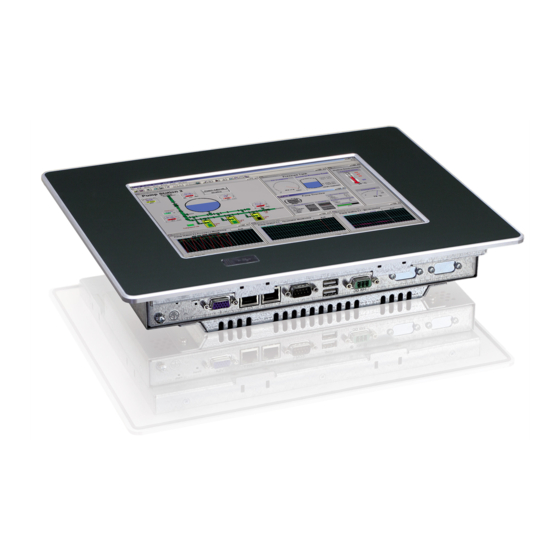
6. Product Description 6. Product Description Before you begin using your M@CII 70/104/121/150 system, you should take a few minutes to learn about the various ports, bays, connectors and indicators that are part of your M@CII 70/104/121/150 system, as well as the components that make up the system. - Page 13 6. Product Description Fig. 1: Bottom view Fig. 2: Right view Fig. 3: Frontal view Fig. 4: Left view Fig. 5: Top view Fig. 6: Rear view In these pictures (Fig. 1 up to Fig. 7) the M@CII system is shown as an M@CII 104 unit. M@CII 70/104/121/150 - User’s Manual (V1.00)
-
Page 14: Front Side View
6. Product Description 6.1. Front Side View Fig. 7: Frontal view of the M@CII 104/121/150 system (shown with a 10" display) 1 Front plate 3 Covered USB interface 2 10"/12.1"/15" TFT display with touch screen (glass to glass technology) Fig. 8: Frontal view of the M@CII 70 system Front plate 7"... -
Page 15: Usb Interface Connector On The Font Side Of The M@Cii 104/121/150 Systems
6. Product Description 6.1.1. USB Interface Connector on the Font Side of the M@CII 104/121/150 Systems This connector USB 2.0 allows you to connect different USB-compatible devices to the M@CII 104/121/150 system. The USB connector is covered by an elastic captive rubber coat. The rubber coat prevents the penetration of fluid, if no device is connected. -
Page 16: Calibrating The Touch Screen
6. Product Description 6.1.4. Calibrating the Touch Screen Calibration serves two purposes: ❏ Sets the active area of the touch screen ❏ Aligns the active area of the touch screen to the screen’s image. Before you calibrate the touch screen, let the system warm up for 30 minutes. Calibration aligns the active touch-sensitive area of the touch screen with the image on the display. - Page 17 6. Product Description Fig. 10: Select “Calibration tab” Fig. 11: Configure the calibration Fig. 12: Calibration acc. selected calibration points and offset For more information about touch screen calibration you find in the Hampshire® TSHARC™ UniWinDriver™ Users Manual for Windows® XP on the www.hampshirecompany.com website.
- Page 18 6. Product Description 6.1.4.2. Calibrate the Touch Screen for Windows® XP Embedded The touch screen (USB connected) of your M@CII system is factory calibrated. The M@CII systems with factory installed Windows® XP Embedded have the executable file for the Hampshire® TSHARC™ touch screen calibration installed under C:\Program Files\tsharc\hwincal.exe and it is linked to the desktop.
-
Page 19: Touch Screen Care And Cleaning
6. Product Description 6.1.5. Touch Screen Care and Cleaning The front panel and the touch screen are covered by a plastic overlay and care should be taken when cleaning it. Mild detergent and water is recommended for cleaning. Use of strong solvents, which could attack paint or plastic, should be avoided. -
Page 20: Bottom View
6. Product Description 6.2. Bottom View Fig. 15: Bottom view of the M@CII 104/121/150 (shown as M@CII 104) Fig. 16: Bottom view of the M@CII 70 Legend for Fig. 15 and Fig. 16: 1 Optional interfaces (shown as CAN-BUS and 7 Reset Button RS422/485 interfaces for M@CII 104/121/150) and a 8 Power LED control indicator (PWR) -
Page 21: Power, Control Indicator, Reset And Grounding
6. Product Description 6.2.1. Power, Control Indicator, Reset and Grounding 6.2.1.1. Power Connector Fig. 17: Detail: DC Power connector at the bottom (rear) side of the M@CII 70/104/121/150 system The DC Power connector (refer to Fig. 15 and Fig. 16 pos. 2 and Fig. 17) provides the power connection of the M@CII 70/104/121/150 system to the main power source via the DC power cable (included) or the AC/DC adapter (not included). - Page 22 6. Product Description 6.2.1.3. Reset Button To restart the M@CII 70/104/121/150 system, e.g. after a system hang-up, press the “RESET” button (refer to Fig. 15 and Fig. 16, pos. 7, and Fig. 18). The system restarts automatically; you don’t have to switch the computer off and on. During a reset all data in the main memory will be erased.
-
Page 23: Interfaces (Rear, Bottom Side Of The System)
6. Product Description 6.2.2. Interfaces (Rear, Bottom Side of the System) Fig. 19: Detail with interfaces for M@CII 104/121/150 systems Fig. 20: Detail with interfaces for M@CII 70 systems Legend for Fig. 19 and Fig. 20: 1 Optional interfaces (shown as CAN-BUS and 3 2x USB (2.0) connector RS422/485 interfaces for M@CII 104/121/150) and 4 COM1 (RS232) serial port connector... -
Page 24: Optional Interfaces
6. Product Description 6.2.3. Optional Interfaces The optional interfaces (Fig. 19, pos. 1 shown as CAN-BUS and RS422/485 interfaces and Fig. 20, pos 1, shown as a serial RS232 interface) must be customized ordered. Depending on your requirements, you can choose the type of the optional interface/s: RS232, RS422/485, RS422/485 isolated 1.5kV and CAN-BUS. - Page 25 6. Product Description Timeout Min. Baudrate SW1 Settings DIP5 DIP6 DIP8 DIP7 10.2ms 1200 9.6ms 9.0ms 8.4ms 7.8ms 7.2ms 6.5ms 5.9ms 4.8ms 2400 4.3ms 3.7ms 3.1ms 2.5ms 4800 1.9ms 1.2ms 9600 0.6ms 19200 Table 5: DIP5, DIP6, DIP7 and DIP8 settings in order to set the needed Timeout and min. Baudtate M@CII 70/104/121/150 - User’s Manual (V1.00)
-
Page 26: Top View
6. Product Description 6.3. Top View Fig. 22: Top side of the system (shown as M@CII 104) Fig. 23: Top side of the system (shown as M@CII 70) Legend for Fig. 22 and Fig. 23: 1 CompactFlash™ card (if ordered) 4 Mounting slots with installed mounting clamp and Allen Screw 2 CompactFlash™... -
Page 27: Left And Right Side View
6. Product Description 6.4. Left and Right Side View Fig. 24: Right side shown as M@CII 104 system Fig. 25: Left side shown as M@CII 104 system Fig. 26: Right side of the M@CII 70 system Fig. 27: Left side of the M@CII 70 system Legend for Fig. -
Page 28: Rear View
6. Product Description 6.5. Rear View Fig. 28: Rear side of the system (shown as a M@CII 104 system) Fig. 29: Rear side of the system (shown as a M@CII 70 system) Legend for Fig. 28, Fig. 29 and Fig. 30: 1 Front panel of the system with seal at the rear side 5 Screws that secure the system cover on the rear side 2 Mounting clamp and Allen Screw for mounting to a... - Page 29 6. Product Description The M@CII 121 is designed as panelmount version. There are eight threaded studs M4 on the rear side of the front plate, that are used for mounting of the M@CII 121 into a subframe or panel. Fig. 30: Rear side of the system (shown as a M@CII 121 system) The M@CII system can be installed with the optional VESA®...
-
Page 30: Vesa Mounting Plate (Option)
6. Product Description ® 6.5.1. VESA Mounting Plate (Option) Each of the mounting plates VESA® 75/100 compliant must be fasten to the appropriate M@CII 70/104/121/150 system (refer to pos. 3, Fig. 28 and Fig. 29) with four M4x6 metric screws. Do not use longer screws than the original screws provided (M4x6 metric). -
Page 31: Installed Etx Baseboard
More information and technical data can be found in the user’s manual of the installed baseboard and ETX Module. You can download the user’s manual of the installed ETX module from our web site at www.kontron.com by selecting the product name. 6.7. DC or AC Power Connection The M@CII 70/104/121/150 system can be connected to a DC power source via a DC power cable (only the power plug terminal is included) and optionally to an AC power source via an AC/DC adapter (not included). -
Page 32: External Ac/Dc Adapter (Option)
6. Product Description 6.7.2. External AC/DC Adapter (Option) The external AC/DC power adapter is an optional part. If ordered, the AC/DC power adapter will be delivered with the power cord suitable for the power supply in your country. Use the power cord suitable for the power supply in your country. Do not remove or alter the grounding prong on the power cord. -
Page 33: Accessing Internal Components
6. Product Description 6.8. Accessing Internal Components This section contains important information that you must read before accessing the internal components. You must follow these procedures properly when handling any board components of the system. Before removing the cover of the M@CII 70/104/121/150 in order to gain access to the internal components, the system must be powered-down and the power cord has to be disconnected from the power source. -
Page 34: Replacing The Lithium Battery
5. Close the unit as described in the chapter 6.8.1 “Configuration of the RS422/RS485 Port” (step 7 and 8). The lithium battery must be replaced with an identical battery or a battery type recommended by Kontron Embedded Computers (Lithium battery 3.0 V for RTC, type: CR2032). The Lithium battery type must be UL listed. -
Page 35: Getting Started
6. Product Description 6.9. Getting started The M@CII 70/104/121/150 system is designed to be powered from a DC power source via a DC power cable (not included). In order to use an AC power source as main power source, can be ordered an AC/DC adapter (not included). 6.9.1. - Page 36 6. Product Description 6.9.1.2. Connecting to AC Power Source via the optional AC/DC Adapter The M@CII 70/104/121/150 system can be optionally connected to an AC power source via the optional AC/DC adapter (refer to Fig. 34). M@CII 70/104/121/150 Display 7"/10.4"/12.1"/15" PC Unit AC/DC Adapter...
-
Page 37: Operating System And Hardware Component Drivers
You can download the relevant drivers for the installed hardware from our web site at www.kontron.com by selecting the product name. The corresponding driver (depending on the installed operating system) for the touch screen controller is available on our website by selecting the “Downloads”... -
Page 38: M@Cii 70/104/150 System Mounting To A Subframe Or Panel
6. Product Description 6.11. M@CII 70/104/150 System Mounting to a Subframe or Panel The system configurations come in the delivering status with mounting clamps and Allen Screws in order to mount the system to a subframe or panel (refer to pos. 2, Fig. 39 or pos. 6, Fig. 40, depending on the system ordered). Fig. - Page 39 6. Product Description In order to ensure IP65 front sealing against dust and water, mount the system on a non-textured surface. Before you install the M@CII 70/104/121/150 system into a panel or a subframe for industrial cabinet, verify the perfect condition of the seal at the rear of the front plate. The seal has to be in place without injury/defects and dirt.
-
Page 40: M@Cii 121 Panelmount Version Of The M@Cii System
6. Product Description 6.12. M@CII 121 Panelmount Version of the M@CII System If you mount the M@CII 121 into an instrument panel or other cabinet use the eight threaded studs M4 at the rear side of the front plate (refer to Fig. 30, pos. 11). Please observe that this unit is designed as the panelmount version of the M@CII system. -
Page 41: Technical Data
2.5" HDD SATA and/or 2.5" HDD SATA (as option) (as option) (as option) BIOS Phoenix/Phoenix-Award (depending on the ETX® board installed) Operating System Refer to the Datasheet for Micro Client II on our Website www.kontron.com M@CII 70/104/121/150 - User’s Manual (V1.00) - Page 42 7. Technical Data Micro Client II M@CII 70 M@CII 104 M@CII 121 M@CII 150 DC Power Connector (3-Pin) (on the rear bottom side) DC Power Terminal (3-Pin) Mounting Clamps (for one screw) Mounting Clamps (for 2 screws) Screw for Mounting Clamps Optional Parts VESA®...
-
Page 43: Electrical Specifications
7. Technical Data 7.1. Electrical Specifications 7.1.1. Electrical Specifications for M@CII 70/104/121/150 System System Type Product Designation Input M@CII 70 24VDC 1.8A max. M@CII 104 24VDC 1.8A max. MicroClient II M@CII M@CII 121 24VDC 1.8A max. M@CII 150 24VDC 1.8A max. 7.1.2. -
Page 44: Mechanical Specifications
7. Technical Data 7.3. Mechanical Specifications 7.3.1. Dimensions for M@CII 70/104/121/150 Dimension for M@CII 70 M@CII 104 M@CII 121 M@CII 150 168 mm (6.61") 312 mm (12.28") Height 277 mm (10.905") 354 mm (13.937") 235 mm (9.25") 380 mm (14.96") Width 348 mm (13.701") 449.4 mm (17.661") - Page 45 7. Technical Data Fig. 45: Frontal view of the M@CII 121 system Fig. 46: Frontal view of the M@CII 150 system M@CII 70/104/121/150 - User’s Manual (V1.00)
- Page 46 7. Technical Data M@CII 70 - rear view M@CII 104 - rear view M@CII 121 - rear view M@CII 70/104/121/150 - User’s Manual (V1.00)
- Page 47 7. Technical Data M@CII 150 - rear view M@CII 70/104/121/150 - User’s Manual (V1.00)
-
Page 48: Ce Directives And Standards
7. Technical Data 7.4. CE Directives and Standards CE Directives Low Voltage Directive 2006/95/EC (Electrical Safety) EMC Directive 2004/108/EC CE Marking 93/68/ECC Electrical Safety Standards EUROPE EN 60950-1: 2006 USA / Canada UL 60950-1:2006 cULus Listed CB Scheme CB Certification Standards EN 61000-3-2:2006 Limits - Limits for harmonic current emissions... -
Page 49: Standard Interfaces - Pin Assignments
8. Standard Interfaces - Pin Assignments 8. Standard Interfaces - Pin Assignments 8.1.1. Ethernet Interfaces (LAN1 and LAN2) PIN# Signal Name RJ45 (female) Connector MDI0+ MDI0- MDI1+ MDI2+ MDI2- MDI1- MDI3+ MDI3- LINK / ACTIVE (green) LED (yellow) 10/100 8.1.2. USB Interfaces (USB) Pin Signal Name 4-pin USB Socket Type A Version 2.0/1.1... -
Page 50: Serial Port (Rs422/Rs485) Configured As Rs422 (4-Channel Mode)
8. Standard Interfaces - Pin Assignments 8.1.4. Serial Port (RS422/RS485) configured as RS422 (4-Channel Mode) Refer to the chapter 6.2.3 “Optional Interfaces”, Table 3, Table 4 and Table 5. Pin Signal Name 9-pin D-SUB Connector (female) TxD- (Transmit Data-) RxD+ (Receive Data+) TxD+ (Transmit Data+) RxD- (Receive Data-) GND (Signal Ground) -
Page 51: Serial Port (Rs422/Rs485) Configured As Rs485 (2-Wire Mode), Half Duplex
8. Standard Interfaces - Pin Assignments 8.1.6. Serial Port (RS422/RS485) configured as RS485 (2-Wire Mode), half duplex Refer to the chapter 6.2.3 “Optional Interfaces”, Table 3, Table 4 and Table 5. Pin Signal Name 9-pin D-SUB Connector (female) Data-) Data+) GND (Signal Ground) 8.1.7. -
Page 52: Technical Support
Be ready to explain the nature of your problem to the service technician. If you have questions about Kontron Embedded Computers or our products and services, you may reach us at the aforementioned numbers, or at: www.kontron.com...
Need help?
Do you have a question about the 2-A0HC Series and is the answer not in the manual?
Questions and answers