
Related Manuals for Kontron KBox B-202-CFL


Summary of Contents for Kontron KBox B-202-CFL
- Page 1 USER GUIDE Abe mit Karlheiz gesporich und ich darf 2020 KBox B-202-CFL Doc. User Guide, Rev 1.3 Doc. ID: 1065-5686 www.kontron.com // 1...
- Page 2 KBox B-202-CFL - User Guide, Rev 1.3 This page has been intentionally left blank www.kontron.com // 2...
- Page 3 In cases of doubt, please contact Kontron. This user guide is protected by copyright. All rights are reserved by Kontron. No part of this document may be reproduced, transmitted, transcribed, stored in a retrieval system, or translated into any language or computer language, in any form or by any means (electronic, mechanical, photocopying, recording, or otherwise), without the express written permission of Kontron.
- Page 4 SCADA/MES applications, artificial intelligence and machine learning. In addition, the KBox B-202-CFL meets Class B meets stricter RFI limits makes it suitable not only for use in industrial environments, but also for use in residential and business areas or in their immediate vicinity, making the KBox B-202-CFL the ideal computer for architecture and graphics offices as well as music studios.
- Page 5 If you have any difficulties using this user guide, discover an error, or just want to provide some feedback, contact Kontron support. Detail any errors you find. We will correct the errors or problems as soon as possible and post the revised user guide on our website.
-
Page 6: Symbols
KBox B-202-CFL - User Guide, Rev 1.3 Symbols The following symbols may be used in this user guide DANGER indicates a hazardous situation which, if not avoided, will result in death or serious injury. WARNING indicates a hazardous situation which, if not avoided, could result in death or serious injury. -
Page 7: For Your Safety
Therefore, in the interest of your own safety and of the correct operation of your new Kontron product, you are requested to conform with the following guidelines. -
Page 8: Lithium Battery Precautions
General Instructions on Usage In order to maintain Kontron’s product warranty, this product must not be altered or modified in any way. Changes or modifications to the product, that are not explicitly approved by Kontron and described in this user guide or received from Kontron Support as a special handling instruction, will void your warranty. -
Page 9: Table Of Contents
KBox B-202-CFL - User Guide, Rev 1.3 Table of Contents Symbols ..........................................6 For Your Safety ........................................7 High Voltage Safety Instructions .................................. 7 Special Handling and Unpacking Instruction ............................7 Lithium Battery Precautions ..................................8 General Instructions on Usage ..................................8 Quality and Environmental Management .............................. - Page 10 KBox B-202-CFL - User Guide, Rev 1.3 5.1. Expansion Options ....................................29 5.1.1. Drive Bay Options ....................................30 5.1.2. Storage Bay Options .................................... 30 5.1.3. PCIe Slot Options ....................................31 5.1.4. Internal Options ....................................32 5.2. Power Options ......................................33 Accessing Components ...................................
-
Page 11: List Of Tables
List of Acronyms ......................................83 About Kontron ........................................84 List of Tables Table 1: Scope of Delivery KBox B-202-CFL Variants ........................... 17 Table 2: Accessories ......................................18 Table 3: KBox B-202-CFL Expansion Option ............................29 Table 4: Drive Bay Options ................................... 30 Table 5: Storage Bay Options .................................. -
Page 12: List Of Figures
Figure 5: Rear Panel KBox B-202-CFL Smart ............................21 Figure 6: Rear Panel KBox B-202-CFL Value ............................22 Figure 7: Rear Panel KBox B-202-CFl Smart Storage .......................... 22 Figure 8: Wi-Fi Antenna ....................................26 Figure 9: Left Side and Right Sid ................................ - Page 13 Figure 39: Mounting Brackets Wall Mount Options with Top Cover facing the Mounting Surface ........52 Figure 40: 24 VDC Wired Power Cable ..............................55 Figure 41: Block Diagram of KBox B-202-CFL Smart Variant without Wi-Fi ................57 Figure 42: Block Diagram of KBox B-202-CFL Value Variant without Wi-Fi................58 Figure 43: Dimensions Front Panel ................................
-
Page 14: 1/ General Safety Instructions
Only connect the product to an external power supply providing the voltage type (AC or DC) and the input power (max. current) specified on the Kontron Product Label and meeting the requirements of the Limited Power Source (LPS) and Power Source (PS2) of UL/IEC 62368-1 . -
Page 15: Electrostatic Discharge (Esd) Precautions
Always place drives and boards PCB-assembly-side down on the foam. 1.3. Instructions for the Lithium Battery The KBox B-202-CFL’s motherboard is equipped with a lithium battery. When replacing the battery observe the instructions described in Chapter 15.3.1: Replacing the Lithium Battery. -
Page 16: 2/ Introduction
KBox B-202-CFL - User Guide, Rev 1.3 2/ Introduction This user guide describes the KBox B-202-CFL made by Kontron and focuses on describing the KBox B-202-CFL’s special features. New users are recommended to study the instructions within this user guide before switching on. -
Page 17: 3/ Scope Of Delivery
KBox B-202-CFL - User Guide, Rev 1.3 3/ Scope of Delivery 3.1. Packaging The KBox B-202-CFL is packaged together with all parts, in a product specific cardboard package designed to provide adequate protection and absorb shock. 3.2. Unpacking To unpack the KBox B-202-CFL, perform the following: Remove packaging. -
Page 18: Accessories
4x Adhesive Chassis feet 2x Wi-Fi antenna (with Wi-Fi option only) Power the KBox B-202-CFL 12 VDC variant with the supplied 12 VDC AC/DC external power supply only. Power the KBox B-202-CFL 24 VDC variant with the supplied 24 VDC wire only. -
Page 19: Product Identification Type Label
KBox B-202-CFL - User Guide, Rev 1.3 3.5. Product Identification Type Label The type label defines the product’s motherboard variants ‘Smart’ or ‘Value’ and the power variant DC-IN 12 VDC, DC-IN 24 VDC or AC-IN 240/100 VAC, and contains specific product information (Model, Power Product Number, Serial Number, Electrical Specification and Compliance.). -
Page 20: 4/ Product Features
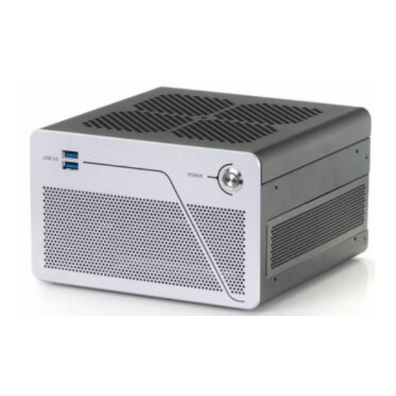
KBox B-202-CFL - User Guide, Rev 1.3 4/ Product Features Before working with the KBox B-202-CFL, Kontron recommends that users take a few minutes to learn about the various parts of the product. All product variants are available in a robust metal chassis that guarantees flexibility in multiple user applications. -
Page 21: Rear Panel Features
KBox B-202-CFL - User Guide, Rev 1.3 4.3. Rear Panel Features The rear panel features the motherboard Smart and Value I/O interfaces, slots for PCI cards or additional mass storage drives, Wi-Fi antenna or breakouts and power connectors. The rear panel variants are:... -
Page 22: Figure 6: Rear Panel Kbox B-202-Cfl Value
11 Audio Line-in/Line-out 17 PCIe slot 1 2x LAN ports (GbE) 12 24 VDC( future option) 18 Ventilation openings (air-output) Figure 7: Rear Panel KBox B-202-CFl Smart Storage PS/2 Keyboard/mouse 2x USB 3.1 Gen 2(red) 13 Potential equalization stud 4x USB 2.0 2x USB 3.1 Gen 1 (blue) -
Page 23: Rear Panel Connectors
The KBox B 202-CFL Smart supports two DP V 1.2 ports and the KBox B 202-CFL Value supports one DP V 1.2 port KBox B-202-CFL Smart -supports up to three displays(2x DP+1x DVI-D) KBox B-202-CFL Value -supports up to two displays (1x DP+1x DVI-D) Using an adapter to convert a DP signal to DVI or HDMI may cause disturbance. -
Page 24: Com Port
4.4.7. USB 3.1 Gen 2 Ports The USB 3.1 Gen 2 ports are backward compatible enabling the connection of USB 3.0 or USB 2.0 devices. Kontron recommends the use of USB 3.1 Gen 2 compliant devices and cables only. The use of devices and cables that violate the USB 3.1 Gen 2 specification may cause non-recognition of the device or read/write errors. -
Page 25: Usb 3.1 Gen 1 Ports
24 VDC variant connects to the DC-IN power jack with the supplied 24 VDC wired power cable. For more, see Chapter 10.6: Power Specification. Power the KBox B-202-CFL 12 VDC variant with the supplied 12 VDC AC/DC external power supply only. -
Page 26: Wi-Fi Antenna Connectors (Option)
KBox B-202-CFL - User Guide, Rev 1.3 4.4.13. Wi-Fi Antenna Connectors (option) The Wi-Fi antennas screw directly on to the Wi-Fi connectors and supporting the following features: Dual band frequencies ( 2.4 GHz & 5 GHz) and Bluetooth (BT) 4.1+HS ... -
Page 27: Left And Right Side Features
KBox B-202-CFL - User Guide, Rev 1.3 4.5. Left and Right Side Features The sides feature ventilation openings for air-output. The ventilation openings on the right side are contained within a removable expansion door. Two pairs of threaded screw holes (Figure 9, pos. 3) lower and (Figure 9, pos. 4) upper are used to attach wall mount brackets, see Chapter 8.2: Mounting Brackets (option). -
Page 28: Top Cover And Bottom Side Features
KBox B-202-CFL - User Guide, Rev 1.3 4.6. Top Cover and Bottom Side Features The top cover features of a metal plate with air-intake ventilation openings and a separate internal metal plate underneath with a circular opening above the internal fan. -
Page 29: 5/ Options
5/ Options 5.1. Expansion Options The supported drives and expansion cards depend on the motherboard specification and chassis space limitation. Kontron recommends expanding the KBox B-202-CFL, before installation in the end environment. Table 3: KBox B-202-CFL Expansion Option Smart Location... -
Page 30: Drive Bay Options
5.1.2. Storage Bay Options Up to two removable 2.5” SSDs without or with RAID (0/1/ JBOD) may be installed in the KBox B-202-CFL’s storage bay on the rear panel or internally two 2.5” SSD with RAID option or one 3.5” HDD may be factory installed. -
Page 31: Pcie Slot Options
KBox B-202-CFL - User Guide, Rev 1.3 Table 5: Storage Bay Options Storage Bay Drive Drive Description Access 2.5” SSD/HDD External Up to two 2.5” SSD/HDD removable drives with lock using SATA III 6 Gb/s interface and supporting single channel, hot swap tray mount. -
Page 32: Internal Options
KBox B-202-CFL - User Guide, Rev 1.3 5.1.4. Internal Options The internal expansion options are an M.2 socket and a mPCIe socket on the mother board. Due to on-board space restrictions, not every M.2 SSD module or mPCIe card combination is possible. Before installing either an M.2 SSD module or mPCIe card users must consider which device populates the neighboring mPCIe socket or M.2 socket. -
Page 33: Power Options
5.2. Power Options The KBox B-202-CFL supports 12 VDC or an optional 24 VDC. Due to different internal components, the 12 VDC and optional 24 VDC are not interchangeable. The KBox B-202-CFL Smart Storage option may implement a 3-pin AC-IN connector for direct connection to a 240/100 VAC mains power outlet. -
Page 34: 6/ Accessing Components
KBox B-202-CFL - User Guide, Rev 1.3 6/ Accessing Components This chapter contains important information that users must read before opening the KBox B-202-CFL to access internal components. Additionally, read and observe the General Safety Instructions contained in this user guide. -
Page 35: Figure 16: Holding Brackets
KBox B-202-CFL - User Guide, Rev 1.3 Remove the two top cover screws on the rear panel and retain the screws for later use. Lift the top cover a few centimeters at the rear of the chassis and then pull the top cover gently away from the front panel to release the top cover from the holding brackets (Figure 16, pos. -
Page 36: Installing And Removing An On-Board Mpcie Expansion Card
KBox B-202-CFL - User Guide, Rev 1.3 6.1.1. Installing and Removing an On-board mPCIe Expansion Card To install an mPCIe card on the motherboard, perform the following: Open the top cover. Locate the mPCIe socket and the corresponding nut on the motherboard. -
Page 37: Drive Bay (Opening And Closing)
KBox B-202-CFL - User Guide, Rev 1.3 6.2. Drive Bay (opening and closing) Before opening the drive bay cover, observe the safety instructions at the start of this chapter. To open the drive bay cover, perform the following: Close all applications. Shut down the product properly using the power button and disconnect the power. -
Page 38: Installing And Removing A 2.5" Ssd Drive
KBox B-202-CFL - User Guide, Rev 1.3 6.2.1. Installing and Removing a 2.5” SSD Drive Before installing a 2.5” SSD drive, observe the SSD drive manufacturer’s instructions. To install a 2.5” SSD in the drive bay, perform the following: Open the drive bay cover. -
Page 39: Installing And Removing The 2.5" Ssd Dual M.2 Raid Module
KBox B-202-CFL - User Guide, Rev 1.3 6.2.2. Installing and Removing the 2.5” SSD Dual M.2 RAID Module Before installing a 2.5” SSD Dual M.2 RAID Module, observe the SSD drive manufacturer’s instructions and to avoid loss of data, observe the information and warnings within this section RAID 1 is the default setting. -
Page 40: Figure 21: Drive Bay With 2.5" Ssd Dual M.2 Raid Module
KBox B-202-CFL - User Guide, Rev 1.3 Figure 21: Drive Bay with 2.5” SSD dual M.2 RAID Module 2.5” SSD dual M.2 RAID module with two M.2 SSD modules (installed bottom side up) SATA connector If the 2.5” SSD dual M.2 RAID module’s RAID array is not configured or the configuration must be changed, see Chapter 13.2: Drive Bay RAID, to set the RAID array and then proceed with step 7. - Page 41 SSD’s screw hole with the 2.5” SSD dual RAID module’s nut. Secure with the screw retained in step 3. Kontron recommends replacing a faulty drive with a drive of the same capacity and type as the mirrored drive. When different capacity drives are used, the working capacity is only as large as the smallest drive’s capacity.
-
Page 42: Expansion Door (Opening And Closing)
KBox B-202-CFL - User Guide, Rev 1.3 6.3. Expansion Door (opening and closing) Before opening the expansion door, observe the safety instructions within this chapter. Operate only when the expansion door is closed and secured; to ensure that users do not have access to internal components during operation. -
Page 43: Figure 24: Pcie Slot Front Pin
KBox B-202-CFL - User Guide, Rev 1.3 Figure 24: PCIe Slot Front Pin Front pin slot 2 Front pin slot 1 Figure 25: PCIe Expansion Slot Holding Latch Holding latch for PCIe card’s bracket tab Aline the expansion card with the corresponding internal PCIe slot. Push the expansion card carefully into the PCIe slots connector, while ensuring the expansion card’s bracket inserts into the holding latch (Figure 25, pos. -
Page 44: Storage Bay
KBox B-202-CFL - User Guide, Rev 1.3 6.4. Storage Bay The storage bay is accessible on the rear panel with up to two removable 2.5” SSDs. Alternatively, up to two non- removable internal 2.5” SSD or a single 3.5” HDD may be factory installed. -
Page 45: 7/ Thermal Considerations
7.1. Active Cooling The KBox B-202-CFL is actively fan cooled. An internal fan draws in air through the top cover’s air-intake ventilation openings (Figure 29 , pos. 1) and distributes the incoming air over the motherboard and other internal components before the air exits the ventilation openings on the right, left, front and rear sides (Figure 30, pos. -
Page 46: Mount Orientation
(top side facing upward) and vertical (all possible mount orientations). Do not mount the KBox B-202-CFL with the top cover facing downwards. When the top cover faces downwards not enough air enters to cool the processor adequately; causing overheating and/or melting. Hence, this creates a possible fire hazard due to hot substances exiting through the top cover’s ventilation openings. -
Page 47: 8/ Installation Instructions
KBox B-202-CFL - User Guide, Rev 1.3 8/ Installation Instructions Operate the KBox B-202-CFL horizontally with the top side facing upward or vertical in all possible mount orientations. Before Installing the KBox B-202-CFL, observe the following instructions. Danger of Fire Mounting the KBox B 202-CFL with the top cover facing downward, may cause overheating or melting and hence may causing a fire hazard or personal injury. -
Page 48: Chassis Feet
To improve stability, positioning the chassis feet between mounting hole and outside edge of the corners. 8.1.1. Chassis Feet Mount (option) Operate the KBox B-202-CFL with chassis feet in the upwards horizontal position only. Figure 32: Chassis Feet Mount Option Danger of Fire Mounting the KBox B 202-CFL with the top cover facing downward, may cause overheating or melting and hence may causing a fire hazard or personal injury. -
Page 49: Mounting Brackets (Option)
Front and rear panel: 10 mm (0.394") Bottom side ( no keep out area required) To mount the KBox B-202-CFL using mounting brackets, perform the following: Consider which set of mounting brackets holes is required for the mounting option: ... -
Page 50: Figure 34: Keep Out Areas - With Top Cover Facing The Mount Surface
KBox B-202-CFL - User Guide, Rev 1.3 Use the mounting bracket’s key mounting holes (Figure 33, pos. 3), to mount on a wall or desktop. Observe compliance to keep out area 10 mm clearance, see Figure 34 and Figure 35. -
Page 51: Mounting On Or Underneath A Desktop
KBox B-202-CFL - User Guide, Rev 1.3 8.2.1. Mounting On or Underneath a Desktop To mount on a desktop/mount surface use the Wall Mount Set, see Table 2: Accessories. Use the lower set of mounting holes on the left and right sides of the chassis (Figure 9, Pos. 3) and use the lower mounting holes on the bracket shown in Figure 33, pos. -
Page 52: Mounting On A Wall
KBox B-202-CFL - User Guide, Rev 1.3 8.2.2. Mounting on a Wall To mount on a wall use the Wall Mount Set, see Table 2: Accessories. With the top cover facing outwards, use the lower pair of mounting holes on the left and right sides of the chassis (Figure 9, pos. 3) and use the mounting bracket holes (Figure 33, pos. -
Page 53: Connecting The Wi-Fi Antenna (Option)
8.3. Connecting the Wi-Fi Antenna (option) Operate the KBox B-202-CFL with Wi-Fi feature by installing the two Wi-Fi antennas included in the delivery to the two Wi-Fi antenna connectors. Note that installing the Wi-Fi antenna increases the original keep out area on the rear side from 10 mm to approximately 45 mm. -
Page 54: 9/ Starting Up
KBox B-202-CFL - User Guide, Rev 1.3 9/ Starting Up The KBox B-202-CFL comes hardware configured, and on request with a pre-installed Operating System (OS) and all the necessary drivers (in accordance with the ordered hardware configuration); enabling full operation when connected to power and switched on for the first time. -
Page 55: Connecting To The Ac Connector (Option)
KBox B-202-CFL - User Guide, Rev 1.3 Figure 40: 24 VDC Wired Power Cable Mating connector to DC-IN Wires ferrules for 24 VDC source. Black wire (-) & white wire (+) To connect the 24 VDC power cable, perform the following: Install any expansion devices and SSDs. -
Page 56: Power On/Off Procedure
KBox B-202-CFL - User Guide, Rev 1.3 9.4. Power On/Off Procedure To switch on the KBox B-202-CFL, connect to the power and briefly press the power button (Figure 4, pos. 3). The power button lights up blue to indicate the powered on state. -
Page 57: 10/ Technical Data
KBox B-202-CFL - User Guide, Rev 1.3 Technical Data 10.1. Block Diagrams Figure 41: Block Diagram of KBox B-202-CFL Smart Variant without Wi-Fi KBox B-202-CFL (Smart) 2x DisplayPort Dual Channel 8th & 9th Den. DDR4-2666 Lntel® /ore™ UDIMM i3 /i5/i7... -
Page 58: Figure 42: Block Diagram Of Kbox B-202-Cfl Value Variant Without Wi-Fi
KBox B-202-CFL - User Guide, Rev 1.3 Figure 42: Block Diagram of KBox B-202-CFL Value Variant without Wi-Fi KBox B-202-CFL (Value) 1x DisplayPort Dual Channel 8th & 9th Den. DDR4-2666 Lntel® /ore™ UDIMM i3 /i5/i7 1x DVI-D (up to 32 GB) 2x LAN (GbE) 2x USB 3.1 Gen 1... -
Page 59: Technical Specification
KBox B-202-CFL - User Guide, Rev 1.3 10.2. Technical Specification Table 8: Motherboard Specification KBox B-202-CFL (Smart) / (Smart Storage) KBox B-202-CFL (Value) Motherboard Type D3633-S D3634-S Form Factor Mini-ITX ( 170mm x 170 mm ) ( 6.7“ x 6.7“) Processor Gen. -
Page 60: Table 11: External Interface Specifications
KBox B-202-CFL - User Guide, Rev 1.3 Storage bay KBox B-202-CFL (Smart Storage) only Internal Type 2.5“ SSD Drive Quantity Up to 2 Capacity 128 GB, 256 GB, 512 GB, 1 TB, 2 TB Interface SATA III, 6Gb/s Installed Internal cage RAID RAID option with 2x 2.5”... -
Page 61: Table 12: Internal Expansion Sockets
KBox B-202-CFL - User Guide, Rev 1.3 Table 12: Internal Expansion Sockets KBox B-202-CFL (Smart / Smart Storage) KBox B-202-CFL (Value) Type mPCIe Quantity Size half-size or full-size mPCIe Interface PCIe Gen 3 PCIe Gen 2 mPCIe (reference option) 802.11ac/abgn Dual-band 2T2R Wi-Fi + Bluetooth 4.0 technology Fi (mPCIe half-size) -
Page 62: Mechanical Specification
KBox B-202-CFL - User Guide, Rev 1.3 10.3. Mechanical Specification Table 16: Mechanical Specifications Dimensions Depth 190 mm (7.48”) Width 190 mm (7.48”) Height 120 mm (4.72”) Weight (Without package) 2.8 kg (6.17 1 lbs.) approx. Mounting Bracket (D x W x H) 187 mm x 45 mm x 20 mm (7.36”... -
Page 63: Environmental Specification
KBox B-202-CFL - User Guide, Rev 1.3 Figure 47: Dimensions Right Side Figure 48: Dimensions Left Side 120 mm 138 mm 37 mm 26 mm 190 mm 11 mm 8.8 mm 201 mm Figure 49: Dimensions with Mounting Brackets 230 mm... -
Page 64: Directives And Standards
KBox B-202-CFL - User Guide, Rev 1.3 10.5. Directives and Standards The KBox B-202-CFL complies with the European Council Directive and the approximation of the laws of the member states. When supplied with optional Wi-Fi variant complies with the Radio Equipment Directive (RED) and the approximation of the laws of the member states. -
Page 65: Power Specification
10.6.1. DC-IN, 12 VDC The KBox B-202-CFL 12 VDC is supplied with an external AC/DC 150 W power supply with a nominal output voltage of 12 VDC. Only use the supplied AC/DC power supply chosen to meet the product’s power specification, power consumption and power protection requirements. -
Page 66: Dc-In, 24 Vdc (Option)
The KBoxB-202-CFL optional 24 VDC variant is supplied with a 24 VDC wired power cable that connects to a separate external 24VDC power source. Only connect to an external DC power source that meets the KBox B-202-CFL’s electrical specification and meets protection and supply limitation requirements. The DC power source must automatically recover from AC power loss and startup under peak loading. -
Page 67: Power Consumption
For more information, contact Kontron Support. 10.6.5. Power Consumption The power supply must provide the level of power required to meet the KBox B-202-CFL’s maximum power consumption. The maximum power consumption depends on the motherboard capacity, system memory and system expansion devices/cards. -
Page 68: 11/ External Interface - Pin Assignments
The DC-IN power connector is a screw on barrel jack (5.5 mm/ 2.5 mm) with center pole. The power connection variants (12 VDC and optional 24 VDC) both connected to the DC-IN power connector. Due to different internal components, the KBox B-202-CFL power variants are not interchangeable. The required input voltage is on the product’s type label. -
Page 69: Usb 2.0 Port Pin Assignment
KBox B-202-CFL - User Guide, Rev 1.3 11.3. USB 2.0 Port Pin Assignment Table 26: USB 2.0 Connector Pin Assignment Signal Name USB 2.0 Connector( Type A) +5 V (fused protected) Data- Data+ Low-active signals are indicated by a minus sign. -
Page 70: Display Port (Dp) V1.2 Connector Pin Assignment
KBox B-202-CFL - User Guide, Rev 1.3 11.5. Display Port (DP) V1.2 Connector Pin Assignment Table 29: Display Port (DP) Connector Pin Assignment Signal Name Signal Name DP1 and DP 2 Connector Link0+ Link0- Link1+ Link1- Link2+ Link2- Link3+ Link3-... -
Page 71: Ps/2 Keyboard Connector Pin Assignment
KBox B-202-CFL - User Guide, Rev 1.3 11.7. PS/2 Keyboard Connector Pin Assignment Table 31: PS/2 Keyboard Connector Pin Assignment Signal Name PS/2 KBD Connector Data +5V (fuse protected) Clock Keyboard-on (low asserted pulse) 11.8. PS/2 Mouse Connector Pin Assignment... -
Page 72: Serial Port Connector Pin Assignment
KBox B-202-CFL - User Guide, Rev 1.3 11.10. Serial Port Connector Pin Assignment Table 34: Serial Interface COM port (RS232) Connector Pin Assignment Signal Name Description 9-pin D-SUB Connector Data Carrier Detect Signal IN SOUT Signal OUT Data Terminal Ready... -
Page 73: 12/ Bios
KBox B-202-CFL - User Guide, Rev 1.3 BIOS The KBox B-202-CFL uses the AMI Aptio 5.x (UEFI) BIOS supported by the D3633-S and D3634-S motherboards and featuring a variety of enhanced functions specifically tailored to the KBox B-202-CFL’s hardware features: ... -
Page 74: Bios Update
If the <DEL> key is not press the POST continues with the test routines. The KBox B-202-CFL uEFI BIOS setup program uses a hot key navigation system. The hot key legend bar is located at the bottom of the setup screens. The following table provides a list of navigation hot keys available in the legend bar. -
Page 75: 13/ Raid
Drive bay RAID Array Internal RAID Array (Smart Storage only) 13.1. Storage Bay RAID Array The KBox B-202-CFL with Storage bay RAID Array is factory installed as RAID 1 by default. Table 36: Storage Bay RAID Array RAID Quantity... -
Page 76: Drive Bay Raid Array
KBox B-202-CFL - User Guide, Rev 1.3 13.2. Drive Bay RAID Array The KBox B-202-CFL with drive bay RAID array is factory installed with RAID 1 by default. Table 37: Drive Bay RAID RAID Number of Interface Position RAID Type RAID Monitoring M.2 SSDs... -
Page 77: Drive Bay Raid Software
Insert into the drive bay with the side of the 2.5” SSD dual M.2 RAID module with the two M.2 SSDs modules facing the inside of the drive bay. Switch on the KBox B-202-CFL. Place a small non-conductive blunt-utensil underneath the 2.5” SSD dual M.2 RAID module where the rest switch is positioned (Figure 51, pos. 3). Press down gently on the 2.5”... -
Page 78: Table 39: S.m.a.r.t. Information Memory Attributes Examples
KBox B-202-CFL - User Guide, Rev 1.3 Table 39: S.M.A.R.T. Information Memory Attributes Examples Memory-attributes Later bad Average erase Unexpected power loss Power on hours Device Life Temperature Power cycle Spare block Flash ID Total bad block Program fail Later bad block read... -
Page 79: Internal Raid Array
KBox B-202-CFL - User Guide, Rev 1.3 13.3. Internal RAID Array The internal RAID array is only available for the Smart Storage variant using the internal storage bay factory installed with two non-removable 2.5” SSDs. Table 42: Internal RAID RAID... -
Page 80: 14/ Technical Support
RMA number. The buyer accepts responsibility for all freight charges for the return of goods to Kontron's designated facility. Kontron will pay the return freight charges back to the buyer's location in the event that the equipment is repaired or replaced within the stipulated warranty period. -
Page 81: 15/ Storage, Transportation And Maintenance
15.3.1. Replacing the Lithium Battery The lithium battery CR 2032 must be replaced with an identical 3 Volt battery or a Kontron recommended battery. To replace the on-board Lithium battery, perform the following: Remove the lithium battery from the holder by pulling the ejector spring outwards. -
Page 82: 16/ Warranty
16.1. Limitation/Exemption from Warranty Obligation In general, Kontron shall not be required to honor the warranty, even during the warranty period, and shall be exempted from the statutory accident liability obligations in the event of damage caused to the product due to failure to observe the following: ... -
Page 83: List Of Acronyms
KBox B-202-CFL - User Guide, Rev 1.3 List of Acronyms Table 43: List of Acronyms ACPI Advanced Configuration Power Interface Operating System AHCI Advanced Host Controller Interface Power Supply Unit BIOS Basic Input Output System RAID Redundant Array of Independent Disks... -
Page 84: About Kontron
KBox B-202-CFL – User Guide, Rev 1.3 About Kontron Kontron is a global leader in embedded computing technology (ECT). As a part of technology group S&T, Kontron offers a combined portfolio of secure hardware, middleware and services for Internet of Things (IoT) and Industry 4.0 applications.
Need help?
Do you have a question about the KBox B-202-CFL and is the answer not in the manual?
Questions and answers