
Related Manuals for Kontron KBox E-110 Series


Summary of Contents for Kontron KBox E-110 Series
- Page 1 USER GUIDE KBox E-110 Series Doc. User Guide, Rev. 1.5 Doc. ID: [To be Determined] www.kontron.com // 1...
- Page 2 KBox E-110 Series - User Guide, Rev. 1.5 This page has been intentionally left blank www.kontron.com // 2...
- Page 3 In cases of doubt, please contact Kontron. This user guide is protected by copyright. All rights are reserved by Kontron. No part of this document may be reproduced, transmitted, transcribed, stored in a retrieval system, or translated into any language or computer language, in any form or by any means (electronic, mechanical, photocopying, recording, or otherwise), without the express written permission of Kontron.
- Page 4 ENVIRONMENTAL DAMAGE (COLLECTIVELY, "HIGH RISK APPLICATIONS"). You understand and agree that your use of Kontron devices as a component in High Risk Applications is entirely at your risk. To minimize the risks associated with your products and applications, you should provide adequate design and operating safeguards.
- Page 5 If you have any difficulties using this user guide, discover an error, or just want to provide some feedback, contact Kontron support. Detail any errors you find. We will correct the errors or problems as soon as possible and post the revised user guide on our website.
- Page 6 KBox E-110 Series - User Guide, Rev. 1.5 Symbols The following symbols may be used in this user guide DANGER indicates a hazardous situation which, if not avoided, will result in death or serious injury. WARNING indicates a hazardous situation which, if not avoided, could result in death or serious injury.
- Page 7 Therefore, in the interest of your own safety and of the correct operation of your new Kontron product, you are requested to conform with the following guidelines.
- Page 8 General Instructions on Usage In order to maintain Kontron’s product warranty, this product must not be altered or modified in any way. Changes or modifications to the product, that are not explicitly approved by Kontron and described in this user guide or received from Kontron Support as a special handling instruction, will void your warranty.
- Page 9 KBox E-110 Series - User Guide, Rev. 1.5 Table of Contents Symbols ..........................................6 For Your Safety ........................................7 High Voltage Safety Instructions .................................. 7 Special Handling and Unpacking Instruction ............................7 Lithium Battery Precautions ..................................8 General Instructions on Usage ..................................8 Quality and Environmental Management ..............................
- Page 10 4.4.3. mPCIe Socket ......................................24 4.4.4. M.2 Socket ......................................25 Accessing Internal Components ..............................26 5.1. Opening and Closing the KBox E-110 Series ............................ 27 5.1.1. Installing an HDD / SSD ..................................28 5.1.2. Installing an M.2 SSD ................................... 29 5.1.3.
- Page 11 Figure 7: Optional VESA mounting kit for KBox E-110 Series ......................32 Figure 8: Drawing of VESA mounting kit for KBox E-110 Series ....................... 32 Figure 9: Hole pattern of VESA mounting kit for KBox E-110 Series ....................33 Figure 10: Securing the mounting bracket ............................... 33 Figure 11: Placing the KBox E-110 Series onto the mounting bracket .....................
- Page 12 KBox E-110 Series - User Guide, Rev. 1.5 Figure 27: BIOS Advanced Menu - DIO Configuration .......................... 62 Figure 28: BIOS Advanced Menu - Network Stack ..........................63 Figure 29: BIOS Advanced Menu - H/W Monitor ........................... 64 Figure 30: BIOS Power Setup Menu ................................65 Figure 31: BIOS Power Setup Menu - WatchDog Timer Configuration...................
- Page 13 Kontron is exempt from accident liability, this also applies during the warranty period. The product has been built and tested according to the basic safety requirements for low voltage (LVD) applications and has left the manufacturer in safety-related, flawless condition.
- Page 14 KBox E-110 Series - User Guide, Rev. 1.5 Additional safety instructions for DC power supply circuits To guarantee safe operation of devices with DC power supply voltages larger than 60 volts DC or a power consumption larger than 240 VA, please observe that: ...
- Page 15 KBox E-110 Series - User Guide, Rev. 1.5 1.1. Electrostatic Discharge (ESD) A sudden discharge of electrostatic electricity can destroy static-sensitive devices or micro-circuitry. Therefore proper packaging and grounding techniques are necessary precautions to prevent damage. Always take the following precautions: Transport boards in ESD-safe containers such as boxes or bags.
- Page 16 KBox E-110 Series - User Guide, Rev. 1.5 2/ Electromagnetic Compatibility For detailed information refer to section 10.3 “CE Directives and Standards”. 2.1. Electromagnetic Compatibility (EU) This product is intended only for use in industrial areas. The most recent version of the EMC guidelines (EMC Directive 2004/108/EC) apply.
- Page 17 If you notice any shipping damage or inconsistencies between the contents and your order, please contact Kontron for help and information. 3.2. Scope of Delivery 3.2.1. Standard 1x KBox E-110 Series (corresponding to the ordered system configuration) 1x Power adapter 1x Power cord 3.2.2.
- Page 18 KBox E-110 Series - User Guide, Rev. 1.5 4/ System Overview The KBox E-110 Series is a fanless system enclosed within a robust compact aluminum chassis with cooling fins, offering the superior qualities for operation in harsh environments. It can be optionally factory-equipped with an mPCIe WLAN card for two antennas and / or mPCIe /M.2 3G / 4G modem adapter card and SIM card slot for one antenna.
- Page 19 4.1.1. System Expansion via SATA Interface The baseboard comes with an onboard SATA 3.0 interface connector and corresponding power connector. Users can expand the KBox E-110 Series with a 2.5" SATA HDD / SSD drive. 4.1.2. System Expansion via mPCIe Card Interface The baseboard comes with an onboard mPCIe interface connector.
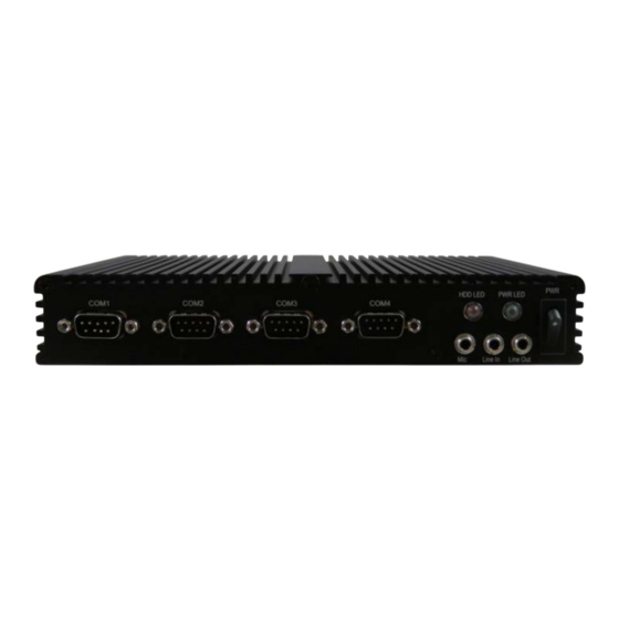
- Page 20 KBox E-110 Series - User Guide, Rev. 1.5 4.2. Front I/O Panel Figure 1: Front I/O Panel Power Switch (see Chapter 4.2.1) Power LED (see Chapter 4.2.2) HDD LED (see Chapter 4.2.3) Line-Out (see Chapter 4.2.4) Mic-In (see Chapter 4.2.5) Line-In (see Chapter 4.2.6)
- Page 21 KBox E-110 Series - User Guide, Rev. 1.5 4.2.5. Mic-In The microphone jack is designed to connect the microphone used for video conferencing, voice narrations, or simple audio recordings. 4.2.6. Line-In The Line-in jack is designed to take input from a higher-powered sound source.
- Page 22 KBox E-110 Series - User Guide, Rev. 1.5 4.3. Rear I/O Panel Figure 2: Rear I/O Panel DC Jack (see Chapter 4.3.1) DP (see Chapter 4.3.2) HDMI (see Chapter 4.3.3) GbE (see Chapter 4.3.4) USB 3.0 (see Chapter 4.3.5) Digital I/O (see Chapter 4.3.6) Wi-Fi Antenna (see Chapter 4.3.7)
- Page 23 Steady Green - Link is up, no activity Off - 10 Mbit/s link established 4.3.5. USB 3.0 The KBox E-110 Series provides four USB 3.0 / 2.0 interface. This connector allows connection of USB 3.0 or USB 2.0 compatible device to the system. 4.3.6. Digital I/O This interface is used to connect digital signals for input and output purposes.
- Page 24 4.4.2. SATA Cable The KBox E-110 Series provides one SATA cable connecting to an onboard SATA 3.0 connector (SATA1) and a HDD power output wafer (CN2) for installing a 2.5" HDD / SSD. An additional pair of brackets is required for holding and fixing the hard disk.
- Page 25 KBox E-110 Series - User Guide, Rev. 1.5 4.4.4. M.2 Socket The KBox E-110 Series reserves one M.2 Key B socket, allowing itself being extended with an M.2 Type 2242 SSD. www.kontron.com // 25...
- Page 26 KBox E-110 Series - User Guide, Rev. 1.5 5/ Accessing Internal Components This section contains important information that you must read before accessing the internal components. You must follow these procedures properly when installing, removing or handling any board. It is recommended to expand your system with additional mPCIe and / or M.2 card(s) before it is installed into an equipment, machine or cabinet.
- Page 27 Close all applications. Shut down the system properly and disconnect the connection to the main power source. Disconnect all peripherals. The KBox E-110 Series should lay on a flat, clean surface with the access cover facing upwards. Loosen and remove the six Phillips screws, that secure the access cover to the chassis. Retain the screws for later use.
- Page 28 Align the HDD / SSD brackets with the internal brackets of the KBox E-110 Series. In order to close the KBox E-110 Series, proceed step 6 & 7 described in the subsection 5.1 "Opening and Closing the KBox E-110 Series".
- Page 29 Press the M.2 SSD down on the side with the fixing hole and secure it with the available fastening screw (Figure 4, pos. 6). In order to close the KBox E-110 Series, proceed step 6 & 7 described in the subsection 5.1 "Opening and Closing the KBox E-110 Series".
- Page 30 The applied cooling method provides adequate cooling of the device during operation and performs a one-way thermal transfer to the chassis. Three sides of the KBox E-110 Series consist of a compact aluminum U-shaped chassis are with cooling fins. The cooling fins provide heat dissipation during operation.
- Page 31 Kontron rejects all liability for any and all damages resulting from operation of the unit with foreign objects inside the chassis. The KBox E-110 Series has to be installed and operated only by trained and qualified personnel. Only personnel with appropriate qualifications, trainings and authorization are permitted to install and work with the Kontron KBox E-110 Series.
- Page 32 Depending on the ordered KBox E-110 Series configuration, your system may be supplied with a VESA mounting kit (Figure 7). The kit consists of two parts: a vertical mounting bracket (Figure 7, pos. 1) to hold the KBox E-110 Series and a small clamp with a hand-screw knob (Figure 7, pos.
- Page 33 Figure 9: Hole pattern of VESA mounting kit for KBox E-110 Series To mount the KBox E-110 Series please proceed according to the steps described: Prepare the mounting surface with four screws and if necessary anchors corresponding to the mounting surface type if no VESA-compliant screw holes are available.
- Page 34 Figure 11: Placing the KBox E-110 Series onto the mounting bracket Place the clamp on the KBox E-110 Series and align its hand-screw knob with the fixing bolt located on the vertical mounting bracket. Then secure it properly (Figure 12).
- Page 35 KBox E-110 Series - User Guide, Rev. 1.5 For a sufficient air circulation around the device, we recommend keep a proper clearance and not mount / operate any other devices within the clearance around the KBox E-110 Series. www.kontron.com // 35...
- Page 36 The KBox E-110 Series is connected by a DC power input jack (Figure 2, pos. 1) to a DC power source. The KBox E-110 Series is delivered with a power adapter to convert AC voltage into DC 12V and a power cord to carry AC power to the power adapter.
- Page 37 8.1. Connecting to DC Power Supply The DC power input jack (Figure 2, pos. 1) is located on the rear side of the KBox E-110 Series. The KBox E-110 Series will be connected to a AC-to-DC power adapter via the supplied male DC power plug and corresponding power cable attached to the adapter.
- Page 38 Please pay attention to the following note. If you have ordered The KBox E-110 Series without a pre-installed operating system, you will need to install the operating system and the appropriate drivers for the system configuration you have ordered (optional hardware components) yourself.
- Page 39 Equipment from Kontron requires only minimum servicing and maintenance for proper operation. For light soiling, clean the KBox E-110 Series with a dry cloth. Carefully remove dust from the surface of the cooling fins of the chassis using a clean, soft brush.
- Page 40 KBox E-110 Series - User Guide, Rev. 1.5 Technical Specifications Table 1: Technical Specifications System Processor Intel® Celeron® N3350 (Dual Core, 2M Cache, up to 2.40 GHz, FCBGA1296, 6 W TDP) Intel® Pentium® N4200 (Quad Core, 2M Cache, up to 2.50 GHz, FCBGA1296, 6 W TDP) ...
- Page 41 KBox E-110 Series - User Guide, Rev. 1.5 Indicator 1x Power LED (on front) 1x Storage LED (on front) Cooling Cooling Method Passive Software OS Support Windows 10, Linux 10.1. Mechanical Specifications Table 2: Mechanical Specifications Construction Aluminum Chassis Dimensions (W x D x H) 210 mm x 135 mm x 35 mm / 8.27"...
- Page 42 KBox E-110 Series - User Guide, Rev. 1.5 10.2. Environmental Conditions Table 3: Environmental Conditions Operating Temperature 0 °C ~ 50 °C / 32 °F ~ 122 °F Storage Temperature -20 °C ~ 80 °C / -4 °F ~ 176 °F...
- Page 43 KBox E-110 Series - User Guide, Rev. 1.5 11/ Standard Interfaces – Pin Assignments Low-active signals are indicated by a minus sign. 11.1.1. DC Jack Table 5: DC Jack (see Figure 2, pos.1) Signal Name DC Jack (female) +12Vin 11.1.2. Ethernet Connectors Table 6: Ethernet Connector (see Figure 2, pos.
- Page 44 KBox E-110 Series - User Guide, Rev. 1.5 11.1.4. HDMI Connector Table 8: HDMI Connector (see Figure 2, pos. 3) Signal Name HDMI Connector Type A Version 1.4 TMDS Data2+ Ground TMDS Data2– TMDS Data1+ Ground TMDS Data1– TMDS Data0+ Ground TMDS Data0–...
- Page 45 KBox E-110 Series - User Guide, Rev. 1.5 11.1.5. DP Connector Table 9: DP Connector (see Figure 2, pos. 2) Signal Name 20-pin DP Connector TX0+ TX0- TX1+ TX1- TX2+ TX2- TX3+ TX3- AUX+ AUX- 11.1.6. RS232 Serial Port Table 10: RS232 Serial Port (see Figure 1, pos. 7)
- Page 46 KBox E-110 Series - User Guide, Rev. 1.5 11.1.7. RS232/422/485 Serial Port Table 11: RS232/422/485 Serial Port (see Figure 1, pos. 8) RS232 RS422 RS485 RS485 COM1, COM2 (9-pin D-SUB Male Connector) Half Full Duplex Duplex DATA- DATA+ 11.1.8. Digital I/O Port Table 12: Digital I/O Port (see Figure 2, pos.
- Page 47 KBox E-110 Series - User Guide, Rev. 1.5 11.1.10. Mic-In Connector Table 14: Mic-In Connector (see Figure 1, pos. 5) Signal Name Mic-In Connector & Corresponding Audio Jack Mic-In_L Ring Mic-In_R Sleeve 11.1.11. Line-In Connector Table 15: Line-In Connector (see Figure 1, pos. 6) Signal Name Line-In Connector &...
- Page 48 Supervisor Password (see Security menu), press <RETURN>, and proceed with step 5. 5. A setup menu will appear. The KBox E-110 Series uEFI BIOS setup program uses a hot key-based navigation system. A hot key legend bar is located on the bottom of the setup screens.
- Page 49 KBox E-110 Series - User Guide, Rev. 1.5 12.2. Setup Menus The Setup utility features shows six menus in the selection bar at the top of the screen: Main Advanced Power Boot Security Save & Exit The Setup menus are selected via the left and right arrow keys.
- Page 50 KBox E-110 Series - User Guide, Rev. 1.5 Figure 15: BIOS Main Menu Screen System Data and Time BIOS SETUP UTILITY Main Advanced Power Boot Security Save & Exit Product Information Product Name KBox E-111 BIOS Version R0.01 (x64) BIOS Build Date...
- Page 51 KBox E-110 Series - User Guide, Rev. 1.5 12.2.2. Advanced Setup Menu The Advanced setup menu provides sub-screens and functions for advanced configurations. The following sub- screen functions are included in the menu: LAN & Audio Configuration Display Configuration ...
- Page 52 KBox E-110 Series - User Guide, Rev. 1.5 Figure 16: BIOS Advanced Menu BIOS SETUP UTILITY Main Advanced Power Boot Security Save & Exit Onboard LAN1 Controller [Enabled] Onboard LAN2 Controller [Enabled] Audio Controller [Enabled] > Display Configuration → ←: Select Screen >...
- Page 53 KBox E-110 Series - User Guide, Rev. 1.5 Figure 17: BIOS Advanced Menu - Display Configuration BIOS SETUP UTILITY Main Advanced Power Boot Security Save & Exit Display Configuration Primary Display [IGD] → ←: Select Screen UWA Frame Buffer Size [256MB] ↑...
- Page 54 KBox E-110 Series - User Guide, Rev. 1.5 Figure 18: BIOS Advanced Menu - Super IO Configuration BIOS SETUP UTILITY Main Advanced Power Boot Security Save & Exit Super IO Configuration > Serial Port 1 Configuration → ←: Select Screen >...
- Page 55 KBox E-110 Series - User Guide, Rev. 1.5 Feature Option Description Serial Port 1 Type [RS232], [RS422], Select an appropriate type for Serial Port 1. [RS485] RS485 Duplex Mode [Half Duplex], [Full Select an appropriate RS485 Duplex Mode. Duplex] RS485 Auto Flow [Disabled], [Enabled] Select whether to enable or disable RS485 Auto Flow Control.
- Page 56 KBox E-110 Series - User Guide, Rev. 1.5 Figure 21: BIOS Advanced Menu - Super IO Configuration - Serial Port 3 Configuration BIOS SETUP UTILITY Main Advanced Power Boot Security Save & Exit Serial Port 3 Configuration Serial Port [Enabled] →...
- Page 57 KBox E-110 Series - User Guide, Rev. 1.5 Feature Option Description Serial Port [Disabled], [Enabled] Select whether to enable or disable Serial Port (COM). Change Settings [Auto], [IO=2E8h; Select an optional setting for Super IO device. IRQ=7;], [IO=3E8h; IRQ=3, 4, 5, 6, 7, 9, 10, 11, 12;], [IO=2E8h;...
- Page 58 KBox E-110 Series - User Guide, Rev. 1.5 Figure 23: BIOS Advanced Menu - CPU Chipset Configuration BIOS SETUP UTILITY Main Advanced Power Boot Security Save & Exit CPU Chipset Configuration EIST [Enabled] → ←: Select Screen Turbo Mode [Enabled] ↑...
- Page 59 KBox E-110 Series - User Guide, Rev. 1.5 Figure 24: BIOS Advanced Menu - SATA Configuration BIOS SETUP UTILITY Main Advanced Power Boot Security Save & Exit SATA Configuration SATA Controller [Enabled] → ←: Select Screen SATA Mode Selection [AHCI] ↑...
- Page 60 KBox E-110 Series - User Guide, Rev. 1.5 Figure 25: BIOS Advanced Menu - USB Configuration BIOS SETUP UTILITY Main Advanced Power Boot Security Save & Exit USB Configuration USB Devices: → ←: Select Screen 1 Keyboard ↑ ↓: Select Item...
- Page 61 KBox E-110 Series - User Guide, Rev. 1.5 Figure 26: BIOS Advanced Menu - Trusted Computing BIOS SETUP UTILITY Main Advanced Power Boot Security Save & Exit Configuration Security Device Support [Disabled] NO Security Device Found → ←: Select Screen ↑...
- Page 62 KBox E-110 Series - User Guide, Rev. 1.5 Figure 27: BIOS Advanced Menu - DIO Configuration BIOS SETUP UTILITY Main Advanced Power Boot Security Save & Exit DIO Configuration User Configuration [Disabled] DIO_0* [Output High] DIO_1* [Output High] DIO_2* [Output High]...
- Page 63 KBox E-110 Series - User Guide, Rev. 1.5 Figure 28: BIOS Advanced Menu - Network Stack BIOS SETUP UTILITY Main Advanced Power Boot Security Save & Exit Network Stack [Disabled] Ipv4 PXE Support* [Enabled] Ipv6 PXE Support* [Enabled] → ←: Select Screen ↑...
- Page 64 KBox E-110 Series - User Guide, Rev. 1.5 Figure 29: BIOS Advanced Menu - H/W Monitor BIOS SETUP UTILITY Main Advanced Power Boot Security Save & Exit PC Health Status CPU Temperature : +34 C → ←: Select Screen System Temperature : +35 C ↑...
- Page 65 KBox E-110 Series - User Guide, Rev. 1.5 12.2.3. Power Setup Menu The Power setup menu provides functions and a sub-screen for power configurations. The following sub-screen function is included in the menu: WatchDog Timer Configuration Figure 30: BIOS Power Setup Menu...
- Page 66 KBox E-110 Series - User Guide, Rev. 1.5 Figure 31: BIOS Power Setup Menu - WatchDog Timer Configuration BIOS SETUP UTILITY Main Advanced Power Boot Security Save & Exit WatchDog Timer Configuration WDT Function [Disabled] → ←: Select Screen ↑ ↓: Select Item Enter: Select +/-: Change Opt.
- Page 67 KBox E-110 Series - User Guide, Rev. 1.5 12.2.4. Boot Setup Menu The boot setup menu lists the for boot device priority order, that is generated dynamically. Figure 32: BIOS Boot Setup Menu BIOS SETUP UTILITY Main Advanced Power Boot Security Save &...
- Page 68 The Security setup menu provides information about the passwords and functions for specifying the security settings. The passwords are case-sensitive. The KBox E-110 Series provides no factory-set passwords. If there is already a password installed, the system asks for this first. To clear a password, simply enter nothing and acknowledge by pressing <RETURN>.
- Page 69 KBox E-110 Series - User Guide, Rev. 1.5 12.2.5.1. Remember the password It is highly recommended to keep a record of all passwords in a safe place. Forgotten passwords results in being locked out of the system. If the system cannot be booted because the User Password or the Supervisor Password are not know, contact Kontron Support for further assistance.
- Page 70 KBox E-110 Series - User Guide, Rev. 1.5 12.2.6. Save & Exit Setup Menu The exit setup menu provides functions for handling changes made to the UEFI BIOS settings and the exiting of the setup program. Figure 34: BIOS Save & Exit Setup Menu...
- Page 71 KBox E-110 Series - User Guide, Rev. 1.5 Appendix A: List of Acronyms The following table does not contain the complete acronyms used in signal names, signal type definitions or similar. A description of the signals is included in the I/O Connector and Internal connector chapters within this user guide.
- Page 72 KBox E-110 Series – User Guide, Rev. 1.5 About Kontron Kontron is a global leader in Embedded Computing Technology (ECT). As a part of technology group S&T, Kontron offers a combined portfolio of secure hardware, middleware and services for Internet of Things (IoT) and Industry 4.0 applications.
Need help?
Do you have a question about the KBox E-110 Series and is the answer not in the manual?
Questions and answers