
Related Manuals for Kontron KBox B-202-CFL


Summary of Contents for Kontron KBox B-202-CFL
- Page 1 USER GUIDE KBox B-202-CFL Doc. Preliminary User Guide, Rev. 0.92 Doc. ID: 1065-5686 www.kontron.com // 1...
- Page 2 KBox B-202-CFL - Preliminary User Guide, Rev. 0.92 This page has been intentionally left blank www.kontron.com // 2...
- Page 3 In cases of doubt, please contact Kontron. This user guide is protected by copyright. All rights are reserved by Kontron. No part of this document may be reproduced, transmitted, transcribed, stored in a retrieval system, or translated into any language or computer language, in any form or by any means (electronic, mechanical, photocopying, recording, or otherwise), without the express written permission of Kontron.
- Page 4 SCADA/MES applications, artificial intelligence and machine learning. In addition, the KBox B-202-CFL meets Class B meets stricter RFI limits makes it suitable not only for use in industrial environments, but also for use in residential and business areas or in their immediate vicinity, making the KBox B-202-CFL the ideal computer for architecture and graphics offices as well as music studios.
- Page 5 If you have any difficulties using this user guide, discover an error, or just want to provide some feedback, contact Kontron support. Detail any errors you find. We will correct the errors or problems as soon as possible and post the revised user guide on our website.
-
Page 6: Symbols
KBox B-202-CFL - Preliminary User Guide, Rev. 0.92 Symbols The following symbols may be used in this user guide DANGER indicates a hazardous situation which, if not avoided, will result in death or serious injury. WARNING indicates a hazardous situation which, if not avoided, could result in death or serious injury. -
Page 7: For Your Safety
Therefore, in the interest of your own safety and of the correct operation of your new Kontron product, you are requested to conform with the following guidelines. -
Page 8: Lithium Battery Precautions
General Instructions on Usage In order to maintain Kontron’s product warranty, this product must not be altered or modified in any way. Changes or modifications to the product, that are not explicitly approved by Kontron and described in this user guide or received from Kontron Support as a special handling instruction, will void your warranty. -
Page 9: Table Of Contents
KBox B-202-CFL - Preliminary User Guide, Rev. 0.92 Table of Contents Symbols ..........................................6 For Your Safety ........................................7 High Voltage Safety Instructions .................................. 7 Special Handling and Unpacking Instruction ............................7 Lithium Battery Precautions ..................................8 General Instructions on Usage ..................................8 Quality and Environmental Management .............................. - Page 10 KBox B-202-CFL - Preliminary User Guide, Rev. 0.92 5.3.2. PCIe Expansion Cards..................................30 Accessing Components ..................................31 6.1. Removing and Installing the Top Cover ............................. 31 6.1.1. Removing the Top Cover ..................................31 6.1.2. Installing the Top Cover ..................................32 6.1.3.
-
Page 11: List Of Tables
Table 13: Chassis Specification ................................... 55 Table 14: Mechanical Specifications ................................. 56 Table 15: Environmental Specification ..............................58 Table 16: Directives and Standards Compliance for KBox B-202-CFL ................... 59 Table 17: PSU 12V Electrical Specification ............................... 60 Table 18: Power Consumption..................................60 Table 19: PSU Power Protection Features .............................. -
Page 12: List Of Figures
Figure 33: Mounting Brackets Wall Mount Options with Top Cover facing the Mounting Surface ........48 Figure 34: Block Diagram of KBox B-202-CFL Smart Variant without Wi-Fi ................51 Figure 35: Block Diagram of KBox B-202-CFL Value Variant without Wi-Fi ................52 Figure 36: Dimensions Front Panel................................ -
Page 13: 1/ General Safety Instructions For It Equipment
Kontron is exempt from accident liability, this also applies during the warranty period. The product has been built and tested according to the basic safety requirements for low voltage (LVD) applications and has left the manufacturer in safety-related, flawless condition. - Page 14 KBox B-202-CFL - Preliminary User Guide, Rev. 0.92 Additional safety instructions for DC power supply circuits To guarantee safe operation of products with DC power supply voltages larger than 60 volts DC or a power consumption larger than 120 VA, observe that: ...
-
Page 15: Grounding Methods
Always place drives and boards PCB-assembly-side down on the foam. 1.2. Instructions for the Lithium Battery The KBox B-202-CFL’s mainboard is equipped with a lithium battery. When replacing the battery observe the instructions described in Chapter 15.3.1: Replacing Lithium Battery. -
Page 16: 2/ Introduction
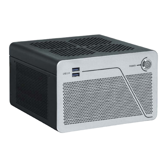
Figure 1: KBox B-202-CFL The KBox B-202-CFL is part of Kontron’s Box PC family designed for high performance, system expandability and low noise needs, intended for 24/7 continuous operation and longtime industrial applications. All components are selected to ensure a long lifetime. -
Page 17: 3/ Scope Of Delivery
Counter sink screws for mounting brackets or vertical stand 3.1. Packaging The KBox B-202-CFL is packaged together with all standard parts listed in Table 1: Scope of Delivery, in a product specific cardboard package designed to provide adequate protection to according the EN 60068-2-31 and absorb shock. -
Page 18: 4/ Product Overview
KBox B-202-CFL - Preliminary User Guide, Rev. 0.92 4/ Product Overview Before working with the KBox B-202-CFL, Kontron recommends that users take a few minutes to learn about the various parts of the KBox B-202-CFL. This chapter provides information regarding KBox B-202-CFL features. -
Page 19: Front Panel View
4.1.1. Power-On Button The power-on button switches on and switched off the KBox B-202-CFL and includes an integrated power LED that lights up blue to indicate the switched on state. Pressing the power-on button for longer than four seconds forces a system shutdown that can lead to a loss of data. -
Page 20: Rear Panel Views
KBox B-202-CFL - Preliminary User Guide, Rev. 0.92 4.2. Rear Panel Views The rear panel contains the mainboard I/O interfaces, two PCIe slots, ventilation holes for air-output, two top cover fastening screws, two Wi-Fi Antenna breakouts and power connector. Figure 5: Rear Panel KBox B-202-CFL (Smart) PS/2 Keyboard 2x USB 3.1 Gen 2 ports... -
Page 21: Ps/2 Keyboard Connector
KBox B-202-CFL - Preliminary User Guide, Rev. 0.92 Figure 6: Rear Panal KBox B-202-CFL (Value) PS/2 Keyboard 2x USB 2.0 ports 15 Slot 1 : PCIe bracte PS/2 Mouse 2 x USB 3.1 Gen 1 ports 16 24 VDC (future option) USB 2.0 port... -
Page 22: Display Port (Dp)
3840 x 2160 (Ultra HD, 4K or 4096 x 2160 (4K x 2K) KBox B-202-CFL-Smart supports up to three displays(2x DP+1x DVI-D) KBox B-202-CFL–Value supports up to two displays (1x DP+1x DVI-D) Using an adapter to convert a DP signal to DVI or HDMI may cause disturbance. -
Page 23: Serial Port (Com)
The USB 3.1 Gen 2 ports are backward compatible enabling the connection of USB 3.0 or USB 2.0 compatible devices. Kontron recommends the use on USB 3.1 Gen 2 compliant devices or cables only. Using devices and cables that violate the USB 3.1 Gen 2 specification may cause conditions such as non-recognition of the device or read/write errors. -
Page 24: Audio Connectors ( Line-In, Line-Out)
KBox B-202-CFL - Preliminary User Guide, Rev. 0.92 4.2.10. Audio Connectors ( Line-IN, Line-OUT) The two audio connectors audio Line-in (blue jack) and audio Line-out (green jack) enable the connection of High Definition (HD) devices or legacy devices. Legacy audio is not supported For the pin assignment, see Chapter 11.9: Audio Line-out and Audio Line-in Connector Pin Assignment. -
Page 25: Left And Right Side Views
KBox B-202-CFL - Preliminary User Guide, Rev. 0.92 4.3. Left and Right Side Views The right and left sides contain ventilation holes for air-output. The ventilation holes on the right side are contained within a removable PCIe expansion card door. To remove the PCI expansion card door release the two screws shown in Figure 7, pos. -
Page 26: Top Cover And Bottom Side Views
KBox B-202-CFL - Preliminary User Guide, Rev. 0.92 4.4. Top Cover and Bottom Side Views The top cover consisting of a metal plate with ventilation holes for air-intake and a separate metal plate underneath with a circular opening above the internal fan. -
Page 27: 5/ System Expansion
KBox B-202-CFL - Preliminary User Guide, Rev. 0.92 5/ System Expansion 5.1. System Expansion Combinations Mass Storage The externally accessible drive bay expansion options are: One 2.5” SDD drive One 2.5” SDD Dual M.2 RAID module Internal expansion options are: ... -
Page 28: Table 3: M.2 Ssd Module And Mpcie Expansion Card Combinations
1x 2.5” SSD DUAL M.2 RAID module (removable) 1 x PCIe slot (1x16) or (1x 8) Two 2.5” SSD drives with Chipset RAID The KBox B-202-CFL Value variant supports only one PCIe x16 slot. www.kontron.com // 28... -
Page 29: Mass Storage Devices
M.2 2242 SSD module may be installed. For supported combinations, see Table 3. For the KBox B-202-CFL Wi-Fi option the mPCIe socket is populated with a half-size mPCIe Wi-Fi card and the M.2 socket use is restricted to a M.2 2242 SSD module. -
Page 30: Expansion Cards
M.2 socket. For the allowed M.2 SSD module/mPCIe card combinations, see Table 3. For the KBox B-202-CFL Wi-Fi option the mPCIe socket is populated with a half-size mPCIe Wi-Fi card and the M.2 socket use is restricted to a M.2 2242 SSD module. -
Page 31: 6/ Accessing Components
Close all applications. Shut down the system properly and disconnect the mains power supply. Disconnect all peripherals. Place the KBox B-202-CFL on a flat, clean and ESD-safe surface. If the Kensington lock is installed, unlock and remove the Kensington lock (Figure 11, pos. 2). -
Page 32: Installing The Top Cover
6.1.2. Installing the Top Cover Installing the top cover, perform the following: Place the KBox B-202-CFL on a flat, clean and ESD-safe surface. Hold the top cover a few centimeters above the main chassis. Do not slide the top cover onto the chassis! Avoid contact and possible damage between the top cover and the internal fan assembly by lifting the top cover vertically. -
Page 33: Installing And Removing On-Board Mpcie Expansion Card
KBox B-202-CFL - Preliminary User Guide, Rev. 0.92 6.1.3. Installing and Removing On-board mPCIe Expansion Card To install an mPCIe card on the mainboard, perform the following: Remove the top cover as described in Chapter 6.1.1: Removing the Top Cover (steps 1 to 6). -
Page 34: Installing And Removing Pcie Cards
Before opening the PCIe expansion card door, observe the safety instructions at the start of this chapter and the PCIe expansion card’s manufactures instructions. It is recommended to expand the KBox B-202-CFL with additional PCIe cards, before installing the system in the end environment. -
Page 35: Figure 15: Pcie Slot Front Pin
KBox B-202-CFL - Preliminary User Guide, Rev. 0.92 Figure 15: PCIe Slot Front Pin Front pin slot 2 Front pin slot 1 Figure 16: PCIe Expansion slot holding latch Holding latch for the PCIe card’s bracket tab Aline the expansion card with the corresponding PCIe slot on the internal riser card. Press the expansion card carefully into the PCIe connector, while ensuring the expansion card’s bracket inserts into the holding latch... -
Page 36: Opening And Closing Drive Bay Cover
6.3. Opening and Closing Drive Bay Cover Before opening the drive bay cover observe the safety instructions at the start of this chapter and the SSD drive manufacturer’s instructions. It is recommended to expand the KBox B-202-CFL, before installation the system in the end environment. -
Page 37: Installing And Removing The Drive Bay 2.5" Ssd Drive
KBox B-202-CFL - Preliminary User Guide, Rev. 0.92 6.3.1. Installing and Removing the Drive Bay 2.5” SSD Drive Before installing a 2.5” SSD drive, observe the SSD manufacturer’s instructions. After installing or removing a 2.5” SSD, the partitioning of the memory maybe different. -
Page 38: Installing And Configuring The 2.5" Ssd Dual M.2 Raid Module
6.3.2. Installing and Configuring the 2.5” SSD Dual M.2 RAID Module The KBox B-202-CFL comes with the 2.5” SSD Dual M.2 RAID module, factory configured as a RAID 1 array. Configuring the 2.5” SSD Dual M.2 RAID module is only required to change the RAID configuration. If one drive fails or is faulty a RAID 1 Array must not be reconfigured by pressing the reset switch, as data on both drives will be lost. -
Page 39: Table 5: Raid Hardware Jumper Settings
Insert the 2.5” SSD dual M.2 RAID module, with the two M.2 SSDs modules facing downwards, into the KBox B- 202-CFL’s externally accessible drive bay (Figure 22). Switch on the KBox B-202-CFL to power the 2.5” SSD dual M.2 RAID module’s SATA connectors (power and data). Place a small nonconductive blunt-utensil underneath the 2.5”... -
Page 40: Replacing A M.2 Ssd Module On The 2.5" Ssd Dual M.2 Raid Module
To replace a failed/faulty M.2 SSD module on the 2.5” SSD Dual M.2 RAID module, perform the following: Remove the 2.5”SSD Dual M.2 RAID module from the KBox B-202-CFL, see Chapter 6.3.2: Installing and Configuring the 2.5” SSD Dual M.2 RAID Module. -
Page 41: 7/ Thermal Considerations
7.1. Active Cooling The KBox B-202-CFL is an active fan cooled system. Air enters through the top cover’s air-intake ventilation holes (Figure 23, pos. 1) and the internal fan distributes the incoming air over the mainboard before the air exits via the ventilation holes on the right, left, front and rear sides (Figure 24, pos. -
Page 42: Mount Orientation
Due to overheating, it is not permitted to mount the KBox B-202-CFL with the top cover facing downwards. If mounted with the top cover facing downwards the KBox B-202-CFL may not be able to take in enough air to cool the CPU adequately;... -
Page 43: 8/ Installation Instructions
KBox B-202-CFL - Preliminary User Guide, Rev. 0.92 8/ Installation Instructions Install the KBox B-202-CFL using the permitted mount orientations only. The permitted mount orientation are horizontal (top side facing upward) and vertical (all possible mount orientations). The KBox B-202-CFL installation accessories are: ... -
Page 44: Chassis Feet
To improve stability positioning the chassis feet between mounting hole and outside edge of the corners. 8.1.1. Chassis Feet Mount (option) The KBox B-202-CFL with chassis feet can be operated in the upwards horizontal position only, see Figure 26. Figure 26: Chassis Feet Mount Option Danger of Fire Mounting the KBox B 202-CFL with the top cover facing downward, may cause overheating or melting and hence may causing a fire hazard or personal injury. -
Page 45: Mounting Brackets (Option)
Bottom side facing mounting surface, use the mounting holes Figure 27, pos. 2 Locate the mounting holes for the required installation on the KBox B-202-CFL’s right side and left side: Lower set of mounting bracket holes, see mount options examples Figure 30 and Figure 32 ... -
Page 46: Figure 28: Keep Out Areas - With Top Cover Facing The Mount Surface
KBox B-202-CFL - Preliminary User Guide, Rev. 0.92 Align the mounting bracket’s mounting holes with either the upper or lower set of mounting bracket holes on either the left side or right side. Fasten the mounting bracket to using a Torx (08 X 60) screwdriver. -
Page 47: Mounting Brackets On A Desktop
KBox B-202-CFL - Preliminary User Guide, Rev. 0.92 8.2.1. Mounting Brackets on a Desktop The different desktop mount options using the mounting brackets are shown in Figure 30 and Figure 31. Use the lower mounting brackets holes on the left and right sides (Figure 7, Pos. 3) to mount on a desktop. To mount underneath a desk top use the upper mounting brackets holes on the left and right sides (Figure 7, Pos 4) and observe a keep out area of 10 mm is used (Figure 27, pos. -
Page 48: Mounting Brackets On A Wall
KBox B-202-CFL - Preliminary User Guide, Rev. 0.92 8.2.2. Mounting Brackets on a Wall The different wall mount options using the mounting brackets are shown in Figure 32 and Figure 33. Use the lower mounting holes on the left and right sides (Figure 7, pos. 3) to mount with the top cover facing outwards. Use the upper mounting holes on the left and right sides (Figure 7,pos. -
Page 49: 9/ Switching On
9.1. Connecting the Power Supply (PSU) To switch on, connect the KBox B-202-CFL to the mains power supply using the PSU provided in the delivery. Follow a best practice cabling procedure before switching on for the first time. The first connection should always be the grounding pin, and then connect the I/O cables. -
Page 50: Switching On /Off
KBox B-202-CFL - Preliminary User Guide, Rev. 0.92 9.2. Switching On /Off The power-on button, with integrated LED, switches on/off the KBox B-202-CFL and lights up blue to indicate the powered on state. Pressing the power-on button for longer than four seconds initiates a forced system shutdown, before switching off the power to the system. -
Page 51: 10/ Technical Data
KBox B-202-CFL - Preliminary User Guide, Rev. 0.92 Technical Data 10.1. Block Diagrams Figure 34: Block Diagram of KBox B-202-CFL Smart Variant without Wi-Fi KBox B-202-CFL (Smart) 2x DisplayPort Dual Channel DDR4-2666 8th Den.Lntel® /ore™ UDIMM i3 /i5/i7 1x DVI-D... -
Page 52: Figure 35: Block Diagram Of Kbox B-202-Cfl Value Variant Without Wi-Fi
KBox B-202-CFL - Preliminary User Guide, Rev. 0.92 Figure 35: Block Diagram of KBox B-202-CFL Value Variant without Wi-Fi KBox B-202-CFL (Value) 1x DisplayPort Dual Channel DDR4-2666 8th Den.Lntel® /ore™ UDIMM i3 /i5/i7 1x DVI-D (up to 32 GB) 2x LAN (GbE) 2x USB 3.1 Gen 1... -
Page 53: Technical Specification
KBox B-202-CFL - Preliminary User Guide, Rev. 0.92 10.2. Technical Specification Table 6: Mainboard Specification KBox B-202-CFL (Smart) KBox B-202-CFL (Value) Mainboard Type D3633-S D3634-S Form Factor Mini-ITX ( 170mm x 170 mm ) ( 6.7“ x 6.7“) Processor Gen. Intel® Core™ i3/i5/i7 Platform Controller Hub Intel®... -
Page 54: Table 9: External Interface Specifications
KBox B-202-CFL - Preliminary User Guide, Rev. 0.92 Table 9: External Interface Specifications KBox B-202-CFL (Smart) KBox B-202-CFL (Value) Front side USB 3.0 2x USB 3.1 Gen 1 Rear side USB 3.0 2x USB 3.1 Gen 1 2x USB 3.1 Gen 1 2x USB 3.1 Gen 2... -
Page 55: Table 12: Software Specification
KBox B-202-CFL - Preliminary User Guide, Rev. 0.92 Table 12: Software Specification KBox B-202-CFL (Smart) KBox B-202-CFL (Value) Operating System (OS) Windows® 10 Windows® 10 Linux-64 Linux-64 BIOS AMI Aptio 5.x (UEFI) BIOS (Modified and adapted for the mainboard) No legacy support and no Master Boot Repair (MBR) installation, due to Intel restrictions. -
Page 56: Mechanical Specification
KBox B-202-CFL - Preliminary User Guide, Rev. 0.92 10.3. Mechanical Specification Table 14: Mechanical Specifications KBox B-202-CFL Dimensions Depth 190 mm (7.48”) Width 190 mm (7.48”) Height 120 mm (2.36”) Weight 2.8 kg (6.17 1 lbs.) approx. without packaging Chassis... -
Page 57: Figure 38: Dimensions Top Cover
KBox B-202-CFL - Preliminary User Guide, Rev. 0.92 Figure 38: Dimensions Top Cover 190 mm 190 mm Figure 39: Dimensions Bottom Side 190 mm 130 mm 190 mm 130 mm www.kontron.com // 57... -
Page 58: Environmental Specification
KBox B-202-CFL - Preliminary User Guide, Rev. 0.92 Figure 40: Dimensions Right Side Figure 41: Dimensions Left Side 138 mm 37 mm 138 mm 26 mm 190 mm 8.8 mm 201 mm Figure 42: Dimensions with Mounting Brackets 230 mm... -
Page 59: Directives And Standards
10.5. Directives and Standards The KBox B-202-CFL plans to comply with the European Council Directive and the approximation of the laws of the member states. When supplied with Wi-Fi, the KBox B-202-CFL plans to comply with the Radio Equipment Directive (RED) and the approximation of the laws of the member states. -
Page 60: Power Specification
An external Power Supply Unit (PSU) AC/DC 150 W with 12 V DC nominal output voltage is supplied with the KBox B-202-CFL to connect the DC-in connector to the mains power supply. Only use the PSU supplied in the delivery that has been chosen to meet the requirements of power specification, power consumption and power protection. -
Page 61: Power Protection
KBox B-202-CFL - Preliminary User Guide, Rev. 0.92 10.6.2. Power Protection The supplied PSU has been chosen to include power protection features to protect the KBox B-202-CFL from damage. This includes power protection features such as short circuit protection, over voltage protection, over temperature protection and over power protection, that shut the PSU down. -
Page 62: 11/ External Interface - Pin Assignments
KBox B-202-CFL - Preliminary User Guide, Rev. 0.92 11/ External Interface - Pin Assignments 11.1. DC IN Power Connector Pin Assignment The DC IN power connector is a barrel jack (5.5 mm/ 2.5 mm) with center pole and an input voltage of 12 V only. -
Page 63: Usb 2.0 Port Pin Assignment
KBox B-202-CFL - Preliminary User Guide, Rev. 0.92 11.3. USB 2.0 Port Pin Assignment Table 22: USB 2.0 Connector Pin Assignment Signal Name USB 2.0 Connector( Type A) +5 V (fused protected) Data- Data+ Low-active signals are indicated by a minus sign. -
Page 64: Display Port (Dp) V1.2 Connector Pin Assignment
KBox B-202-CFL - Preliminary User Guide, Rev. 0.92 11.5. Display Port (DP) V1.2 Connector Pin Assignment Table 25: Display Port (DP) Connector Pin Assignment Signal Name DP1 and DP 2 Connector Signal Name Link0+ Link0- Link1+ Link1- Link2+ Link2- Link3+... -
Page 65: Ps/2 Keyboard Connector Pin Assignment
KBox B-202-CFL - Preliminary User Guide, Rev. 0.92 11.7. PS/2 Keyboard Connector Pin Assignment Table 27: PS/2 Keyboard Connector Pin Assignment Signal Name PS/2 Kbd Connector Data +5V (fuse protected) Clock Keyboard_On ( low asserted pulse) 11.8. PS/2 Mouse Connector Pin Assignment... -
Page 66: Serial Port Connector Pin Assignment
KBox B-202-CFL - Preliminary User Guide, Rev. 0.92 11.10. Serial Port Connector Pin Assignment Table 30: Serial Interface COM port (RS232) Connector Pin Assignment Signal Name- RS232 9-pin D-SUB Connector (Data Carrier Detect) (Signal In) SOUT (Signal out)) (Data Terminal Ready) -
Page 67: 12/ Bios
KBox B-202-CFL - Preliminary User Guide, Rev. 0.92 BIOS The KBox B-202-CFL uses the AMI Aptio 5.x (UEFI) BIOS supported by the mainboard and featuring a variety of enhanced functions specifically tailored to the KBox B-202-CFL’s hardware features: Recovery BIOS ... -
Page 68: Bios Update
The Setup menu appears. The KBox B-202-CFL uEFI BIOS Setup program uses a hot key navigation system. The hot key legend bar is located at the bottom of the Setup screens. The following table provides a list of navigation hot keys available in the legend bar. - Page 69 Run the update file “Flash BIOS Update – Desk Flash Instant” Perform the on-screen instructions If the system fails to boot, the updated BIOS maybe damaged, contact Kontron Support. To update the BIOS using a FAT32 formatted USB stick, perform the following: Download the “Admin package-compressed Flash files”...
-
Page 70: 13/ Raid
RAID The KBox B-202-CFL supports two RAID arrays each with a maximum of two drives for RAID 1 or RAID 0 support. The KBox B-202-CFL Smart and Value variants both support a 2.5” SSD Dual M.2 RAID module option in the externally accessible drive bay. -
Page 71: Notification Tab
The chipset RAID configures a RAID 0 or RAID 1 array on two internal SATA connected 2.5” SSDs ,using the BIOS setup. When using a RAID array, to avoid possible data loss, actively monitor the RAID array to anticipate problems and prevent a possible fail. Kontron recommends performing regular backups on a RAID 0 configuration. -
Page 72: Technical Support
NOTE: Depending on capacity and usage of the drives, the rebuild may take a while to complete. 14.2. Technical Support Should a problem occur that cannot be solved using the trouble shooting information above contact Kontron’s Support Department: E-mail: support@kontron.com... -
Page 73: Returning Defective Merchandise
RMA number. The buyer accepts responsibility for all freight charges for the return of goods to Kontron's designated facility. Kontron will pay the return freight charges back to the buyer's location in the event that the equipment is repaired or replaced within the stipulated warranty period. Follow these steps before returning any product to Kontron. -
Page 74: 15/ Storage, Transportation And Maintenance
Stubborn dirt should be removed using a mild detergent and a soft cloth 15.3.1. Replacing Lithium Battery The lithium battery CR 2032 must be replaced with an identical 3 Volt battery or a Kontron recommended battery. To replace the on-board Lithium battery, perform the following: Remove the lithium battery from the holder by pulling the ejector spring outwards. -
Page 75: 16/ Warranty
16.1. Limitation/Exemption from Warranty Obligation In general, Kontron shall not be required to honor the warranty, even during the warranty period, and shall be exempted from the statutory accident liability obligations in the event of damage caused to the product due to failure to observe the following: ... -
Page 76: Appendix A: List Of Acronyms
KBox B-202-CFL - Preliminary User Guide, Rev. 0.92 Appendix A: List of Acronyms Table 37: List of Acronyms (Example) AHCI Advanced Host Controller Interface REACH Registration, Evaluation, Authorization and Restriction of Chemicals Application Programming Interface Return of Material Authorization BIOS... -
Page 77: About Kontron
KBox B-202-CFL – Preliminary User Guide, Rev. 0.92 About Kontron Kontron is a global leader in embedded computing technology (ECT). As a part of technology group S&T, Kontron offers a combined portfolio of secure hardware, middleware and services for Internet of Things (IoT) and Industry 4.0 applications.
Need help?
Do you have a question about the KBox B-202-CFL and is the answer not in the manual?
Questions and answers