Table of Contents
Advertisement
Quick Links
Advertisement
Table of Contents

Related Manuals for Kontron MOPSlcdLX


Summary of Contents for Kontron MOPSlcdLX
- Page 1 Kontron User’s Guide ® MOPSlcdLX ® Document Revision 2.6...
-
Page 2: Table Of Contents
External RTC Battery...................10 Environmental Specifications...............12 4.4.1 Temperature .....................12 4.4.2 Humidity....................12 MTBF.......................12 5. CPU, CHIPSET AND SUPER I/O................. 13 CPU......................13 Chipset....................13 Super I/O....................13 6. SYSTEM MEMORY ....................14 7. ISA BUS EXPANSION ..................... 15 PC/104 Bus (ISA part) ................15 Kontron User's Guide MOPSlcdLX... - Page 3 13. PS/2-MOUSE INTERFACE..................27 13.1 Connector ....................27 14. USB INTERFACE....................28 14.1 Connector ....................28 14.2 Limitations....................28 15. FLOPPY-DRIVE INTERFACE..................29 15.1 Connector ....................29 16. IDE INTERFACE..................... 30 16.1 Connector ....................30 17. ETHERNET CONTROLLER ..................32 17.1 Connector ....................32 Kontron User's Guide MOPSlcdLX...
- Page 4 24.12.1 JIDA BIOS Extension ..................49 24.12.2 Remote Control Client Extension..............49 24.12.3 LAN PXE ROM ....................50 APPENDIX A: SYSTEM RESOURCEN................. 51 Interrupt Request Lines ................51 Direct Memory Access (DMA) Channels ............52 I/O Address Map..................53 Memory Map .....................54 Kontron User's Guide MOPSlcdLX...
- Page 5 APPENDIX C: LITERATURE HINTS................... 62 General PC Architecture ................62 Buses ......................62 C.2.1 ISA, Standard PS/2 - Connectors..............62 C.2.2 PCI/PC-104 ....................63 Ports.......................63 C.3.1 RS-232 Serial....................63 C.3.2 ATA......................63 C.3.3 USB ......................63 Programming....................64 APPENDIX D: REVISION HISTORY .................. 65 Kontron User's Guide MOPSlcdLX...
-
Page 6: User Information
- no liability is taken for any inaccuracies. Manual is subject to change without prior notice. For the circuits, descriptions and tables indicated, Kontron assumes no responsibility as far as patents or other rights of third parties are concerned. -
Page 7: Warranty
Kontron Embedded Modules GmbH will not be responsible for any defects or damages to other products not supplied by Kontron Embedded Modules GmbH that are caused by a faulty Kontron Embedded Modules GmbH product. -
Page 8: Introduction
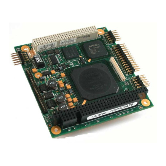
Introduction MOPSlcdLX MOPSlcdLX SBC modules support the AMD LX800 Embedded System Platform. The MOPSlcdLX is a versatile, low-cost, low-power module that conforms to the industry standard 90mm x 96mm PC/104 form factor. The board’s chipset includes a AMD Geode LX800 CPU and the Companion Chip CS5536. -
Page 9: Mops Family
Each MOPS module is characterized by the same pinout for the keyboard, COM1 and COM2, 44-pin IDE, LPT, and 1 LAN. These homogeneous features facilitate easy upgrades within the Kontron Embedded Modules GmbH MOPS PC/104 product family. Whenever a LCD panel is required, MOPS products with onboard graphics controllers serve as the right choice. -
Page 10: Getting Started
Chapter 3 Getting Started Getting Started The easiest way to get the MOPSlcdLX board running is to use a starter kit from Kontron Embedded Modules GmbH. Take the following steps: ‚ Connect the power supply to the starter kit baseboard (part of the starter kit). -
Page 11: Specifications
® • UDMA Peripheral Component Interconnect (PCI) Bus Master IDE ports (up to two devices) Universal Serial Bus (USB) ® • Two USB 2.0 ports (OHCI/EHCI) • USB legacy keyboard support • USB floppy boot support Kontron User's Guide MOPSlcdLX... - Page 12 Only 8 bit DMA available • ISA bus master mode not suppo rted External PCI Bus ® • 33 MHz PCI clock • Only 3.3V PCI cards su pported • Onboard 3 .3V V switchable by resistor Kontron User's Guide MOPSlcdLX...
-
Page 13: Block Diagram
Interface BIOS CPLD (JILI) Super-I/O W83627 Floppy Interface Parallel Hardware Port Monitor Temperature PS/2 Serial Interface Ports Voltage ISA Bridge F 85226 Keyboard COM A Transformer Mouse COM B Network Controller 82551ER PC/104 Connector PC/104plus Connector Kontron User's Guide MOPSlcdLX... -
Page 14: Mechanical Specifications
One 2x32 pin stackthrough and one 2x20 pin stackthrough connector ® 4.2.2 PC/104+ Bus Connector (PCI part) One 4x30 pin stackthrough connector ® 4.2.3 Module Dimensions 96 x 90 mm (3.77” x 3.55”) ® 4.2.4 Weight 98 g (full feature version without memory module) ® Kontron User's Guide MOPSlcdLX... -
Page 15: Electrical Specifications
AMD LX800 (500 MHz) Power t.b.d. Consumption (calculated theoretical values from all components maximum supply currents) 4.3.5 External RTC Battery Voltage range: 2.4 V - 3.6 V (typ. 3.0 V) ® Maximum current: 10 μA ® Kontron User's Guide MOPSlcdLX... - Page 16 If the battery of this product however is accessible by the end user, it is in the respon sibility of the customer to give the corresponding safety instructions in the required language(s). Kontron User's Guide MOPSlcdLX...
-
Page 17: Environmental Specifications
Battery life depends on both temperature and operating conditions. When the Kontron unit has external power; the only battery drain is from leakage paths. -
Page 18: Cpu, Chipset And Super I/O
Internal Real-Time clock with CMOS RAM Super I/O The exter nal Super I/O WINBOND W83627 offers the following features: Integrated keyboard controller with PS/2 mouse support ® Two serial ports and one multi-mode parallel port ® Floppy disk controller ® Kontron User's Guide MOPSlcdLX... -
Page 19: System Memory
SDRAM module is used for main memory and graphic memory on the MOPSlcdLX. Shared Memory Architecture (SMA) manages the sharing of the system memory between phic controller and processor. Therefore, the full m emory size is not available for software applications. -
Page 20: Isa Bus Expansion
Chapter 8 PCI Bus Expansion ISA Bus Expansion The design of the MOPSlcdLX follows the standard PC/104 form factor and offers ISA bus signals for the use of standard PC/104 adapter cards. PC/104 Bus (ISA part) The PC/104 bus consists of two connectors that use 104 pins in total. -
Page 21: Pci Bus Expansion
Configuration of V and VCC The PCI Bus of the MOPSlcdLX is 3.3V only. The default settings for V and VCC are not connected. If it is ensured that the PCI expansion cards are types of 3.3V only, Zero-Ohm bridges can be set (see picture 1 and picture 2). -
Page 22: Graphics Interface
JILI cable. On occasion, backlight voltage has to be adjusted on the cable. Even though the MOPSlcdLX is a +5V only board, you need to supply the +12V for the backlight converter additionally when using such a converter type. The onboard +3.3V circuitry and the +3.3V logic voltage of low-voltage panels are powered by separa te voltage regulators. -
Page 23: Connecting A Lcd Panel
Graphics Interface Connecting a LCD Panel To determine whether your panel display is supported, check the Kontron Web site for panel lists. We regu- larly update the list of panels that have been tested with the MOPSlcdLX. If you use one of those adapters supplied by Kontron, configuration is easy: ‚... -
Page 24: Extended Vesa Vga Modes
Tx/Rx27 Red 6 (e.g. even: RE6 or ER6) Tx/Rx5 Red 7 Tx/Rx10 Green 6 (e.g. even: GE6 or EG6) Tx/Rx11 Green 7 /Rx16 Blue 6 (e.g. even: BE6 or EB6) Tx/Rx17 Blue 7 Tx/Rx23 not used Kontron User's Guide MOPSlcdLX... -
Page 25: Uds Specification (Kontron)
For these information please check the display datasheet. With the MOPSlcdLX board the parameters for the typical detailled t iming out of the datasheet might not be correct for centering the picture. In general the exact positioning of the picture has to be obtained experimental. -
Page 26: Summary Of Used Displayid Parameters
Chapter 9 Graphics Interface 9.8.1 Summary of used DisplayID parameters Only a part of the parameters used in the DisplayID Windows tool are interpreted by the MOPSlcdLX board. The following table shows a sum mary o f the u sed DisplayID parameters. -
Page 27: Serial-Port Interfaces
- the wires have the right diameter to withstand the maximum available current. - to enclosure of the peripheral device fulfills the fire-protecting conditions of IEC/EN 60950. To find the location of the serial ports on the MOPSlcdLX board, please see the Appendix "Connector Lay- out". -
Page 28: Parallel-Port Interface
- the wires have the right diameter to withstand the maximum available current. - to enclosure of the peripheral devi ce fulfills the fire-protecting conditions of IEC/EN 60950. o find the location of the parallel port on the MOPSlcdLX board, please see the Appendix "Connector Lay- ut". Kontron User's Guide MOPSlcdLX... -
Page 29: Keyboard Interface
- to enclosure of the peripheral device fulfills the fire-protecting conditions of IEC/EN 60950. Pin 9 and pin 3 (power connector) are not decoupled. Do not connect two batteries. To find the location of the keyboard and feature connector on the MOPSlcdLX board, please see the Appendix "Connector Layout". -
Page 30: Signal Descriptions
A battery is not needed to hold CMOS setup data. Your configurations for hard disks, ® floppy drives, and other peripherals are saved in an o nboard EEPROM. However, you need a battery to save the CMOS date and time when power supp ly is turned off Kontron User's Guide MOPSlcdLX... -
Page 31: Example Connection At-Keyboard And Other Functions
Chapter 12 Keyboard Interface 12.2.1 Example Connection AT-keyboard and Other Functions 6 PIN MINI-DIN (PS/2 STYLE) (KBCLK) (GND) (+5V Vc (KBDAT) 5 PIN DIN 180° (DIN41524) (Speaker) (KBCLK) (GND) (KBDAT) (+5V Vcc) (PWRGOOD) (/RESIN) (/KBLOCK) (BATT) Kontron User's Guide MOPSlcdLX... -
Page 32: Ps/2-Mouse Interface
- to enclosure of the peripheral device fulfills the fire-protecting conditions of IEC/EN 60950. To fin d the location of the PS/2 mouse connector on the MOPSlcdLX board, please see the Appendix "Connector Layout". Kontron User's Guide MOPSlcdLX... -
Page 33: Usb Interface
- the wires have the right diameter to withstand the maximum available current. - to enclosure of the peripheral device fulfills the fire-protecting conditions of IEC/EN 60950. To find the location of the USB ports on the MOPSlcdLX board, please see the Appendix "Connector Layout". 14.2 Limitations The power contacts for USB devices on Pin 1 and Pin 4 are protected. -
Page 34: Floppy-Drive Interface
- the wires have the right diameter to withstand the maximum available current. - to enclosure of the peripheral device fulfills the fire-protecting conditions of IEC/EN 60950. To find the location of floppy-drive interface on the MOPSlcdLX board, please see the Appendix "Connector Layout". -
Page 35: Ide Interface
IDE Interface 16. IDE Interface The MOPSlcdLX features one EIDE interface (Ultra DMA66 mode) that can drive two hard disks. When two devices share a single adapter, they are connected in a master/slave, daisy-chain configuration. If only one drive is in the system, you must set it as the master. - Page 36 IEC/EN 60950. Ω Pin 28 is connected with 470 to Ground for Cable Select IDE devices. To find the location of IDE interface on the MOPSlcdLX board, please see the Appendix "Connector Layout". Kontron User's Guide MOPSlcdLX...
-
Page 37: Ethernet Controller
Ethernet Controller 17. Ethernet Controller The MOPSlcdLX uses a Intel 82551ER PCI Fast Ethernet Controller. The network controllers support 10/100 Base-T interfaces. The devices auto-negotiate the use of a 10 Mbit/sec or 100 Mbit/sec connection. An error-free operation can be guaranteed up to 100 me ters CAT4 ethernet cable. -
Page 38: Power Connector
MOPSlcdLX is intended for use as a stand-alone module without a backplane. You eed to have a power connector available on the board for direct power supply. The MOPSlcdLX is a +5V only boar d. Peripherals can obtain additional voltage from the power connector next to the PC/104 bus. The additional voltages (+12V, -5V and -12V) are not generated onboard the MOPSlcdLX. -
Page 39: External Battery
Chapter 18 Power Connector A system using the MOPSlcdLX also can be supplied from the PC/104 bus connectors. If only those supply voltages pins are used, the following limitations apply: Power Number of Pins on Max. Current ISA Part per Pin... -
Page 40: Crisis Management
ƒ switch th e second jumper JP7000 as depicted, wait for 3 seconds „ put the jumper back as it was before Then continue with the steps from the no battery case. Kontron User's Guide MOPSlcdLX... -
Page 41: Cpu/Memory Speed
CPU Speed Memory Speed 200 MHz DDR200 333 MHz DDR200 333 MHz DDR266 400 MHz DDR200 400 MHz DDR266 433 MHz DDR266 500 MHz DDR266 Kontron User's Guide MOPSlcdLX... -
Page 42: Watchdog Timer
Watchdog Timer 21. Watchdog Timer The watchdog timer of the MOPSlcdLX can issue a reset to the system. The watchdog timer circuit has to be triggered within a specified time by the application software. If the watchdog is not triggered because proper software execution fails or a hardware malfunction occ urs, it will reset the system. -
Page 43: Special Hardware Hints
Some problems exists when using the KONTRON ADA9 PC/104+ Evaluation Board (re- ® fering to PCI Slots). KONTRON can not guarantee that all PCI cards runs error-free 22.3 Memory Issues In case you encounter problems during file operations (i.e. copy procedure during Windows installation), these can usually be fixed by decreasing the memory speed. -
Page 44: Onboard Device Configuration
Advanced BIOS Features / PS2 Mouse Function USB Interface Advanced Chipset Features / USB Controller Advanced BIOS Features / First Boot Device Advanced BIOS Features / Second Boot Device Advanced BIOS Features / Third Boot Device Kontron User's Guide MOPSlcdLX... - Page 45 Advanced Chipset Features / Watchdog Timeout Advanced Chipset Features / Watchdog Delay Temperature Monitoring PC Health Status / Shutdown Temperature BIOS Extensions Advanced BIOS Features / JRC Extension Advanced BIOS Features / Darkboot - Custom Logo Kontron User's Guide MOPSlcdLX...
-
Page 46: Setup Guide
BIOS Setup menus documented in this section represent those found in most models of the MOPSlcdLX. The BIOS Setup for specific models can differ slightly. -
Page 47: Main Menu
Extended Memory Displays amount of extended memory de- tected during boot-up Extended memory = capacity of memory module – selected frame buffer memory size Total Memory Displays amount of total memory detec- ted during boot-up Kontron User's Guide MOPSlcdLX... -
Page 48: Ide Master Or Slave Submenus
Standard CDROM or DVD drive CDROM Primary slave IDE hard drive Harddisk 1 USB diskette drive USB-FDD USB ZIP drive USB-ZIP USB CDROM drive USB-CDROM USB harddisk drive USB-HDD Ethernet controller with LAN-Boot-ROM Disables boot device entry Disabled (Third) Kontron User's Guide MOPSlcdLX... - Page 49 Shadow Read/Write Disabled Normally s hadow area only readable. Use this opti- on to enable Write operation Enabled Memory Hole at 15M-16M Disabled Enables or disables the memory hole at 15MB for ISA bus access Enabled Kontron User's Guide MOPSlcdLX...
-
Page 50: Advanced Chipset Features
Watchdog Timeout Selects maximum trigger period in, 5.5min 10.5 min, 30.5 Watchdog Delay s, 5s, 10s, 30s Selects time until the watchdog counter starts counting. Useful to handle longer boot times 1mi n , 5.5m 10.5min, 30.5min Kontron User's Guide MOPSlcdLX... -
Page 51: Integrated Peripherals
Selects I/O base and IRQ of serial port respectively disables the port 378/IRQ7 278/IRQ5 3BC/IRQ7 Parallel Port Mode Standard Sets the mode for parallel port Standard = bidirectional EPP = Enhanced Parallel Port specification EPP Mode Select EPP1.9 Selects the EPP specification EPP1.7 Kontron User's Guide MOPSlcdLX... -
Page 52: Pnp/Pci Configurations
C, 115 C, 125 Board Voltage +Vcore Vcore voltage (generated onboard) Boar d Voltage +3.3V 3.3V voltage (generated onboard) System V oltage +5. 5.0V voltage (external power supply) System Voltage +12.0V 12.0V voltage (external power supply) Kontron User's Guide MOPSlcdLX... -
Page 53: Display Board Information
Shows the Northbridge (LX800) chip revision CS5536 Chip Rev. Shows the Southbridge (CS5536) chip revision Board Class Shows the KONTRON specific board class (JIDA entry) Board Name Shows the KONTRON specific board name (JIDA entry) Hardware Version Shows the KONTRON specific hardware version (JIDA entry) -
Page 54: Special Bios Hints
24.12.2 Remote Control Client Extension You can remotely control the MOPSlcdLX using software available from Kontron (JRC-1, Part Number 96047- 0000-00-0). This software tool can communicate with the board via one of the serial ports. During boot-up, the system BIOS scans the serial ports for an available JRC connection. If detected, it loads the JRC client... -
Page 55: Lan Pxe Rom
PXE support, is not the resp onsibility of Kontron. The PXE ROM extension is loaded into the f irst free memory area between C8000h and DFFFFh, and a 48K block of m emory is shadow Kontron User's Guide MOPSlcdLX... -
Page 56: Appendix A: System Resourcen
Appendix A: System Resourcen A.1 Interrupt Request L ines Please note that Kontron PC/104 devices were designed after the draft of P996 Specification for ISA systems. Because of this, shareable interrupts are not supported. Some PC/104 add-on board manu- facturers do not follow the P996 Specification and allow shareable interrupts. -
Page 57: Direct Memory Access (Dma) Channels
Note (1) Cascade ---- Note (2) ---- Note (2) ---- Note (2) Note: If the „used for“ - device is disabled in setup, the corresponding DMA is available for other devices. 16 bit DMA channels not available. Kontron User's Guide MOPSlcdLX... -
Page 58: I/O Address Map
Appendix A System Resourcen A.3 I/O Address Map The I/O-port addresses of the processor module MOPSlcdLX are functionally identical to a standard PC/AT. All addresses not mentioned in this table should be available. We recommend that you do not use I/O addresses below 0110h with additional hardware fo r compatibility reasons, even if available. -
Page 59: Memory Map
Appendix A System Resourcen A.4 Memory Map The MOPSlcdLX processor module can support up to 1 GB memory modules. As the MOPSlcdLX uses Shared Memory Architecture (SMA) he amount of g raphic memory re duce s the availa ble amount of system me- mory. -
Page 60: Smbus Devices
Appendix A System Resourcen A.6 SMBus Devices The MOPSlcdLX uses an onboard System Management (SM) Bus. This bus is not available on an peripheral connector and therefore cannot be used for external SMBus devices. SMBus Address SM Device Comment mp. Se nsor (LM86 Onboard temperature sensor. -
Page 61: Appendix B: Connector Layout
X12001 X15006 X15007 X14001 X11000 JP14002 JP7000 X10000 Pin 1 The Board as depicted is a mo del only , show ing the positions of the connect ors. For pincount an d pinning please see the following tables. Kontron User's Guide MOPSlcdLX... - Page 62 Appendix B Connector Layout Kontron User's Guide MOPSlcdLX...
-
Page 63: Connector Functions & Interface Cables
X10000c Power 2.54mm 8 pos. Connector (EPT 962-60043-12 or compatible for board to board connection) X12001 CRT Monitor 1.25mm 6 pos. KAB-VGA-2 for DSUB-15 Connector (Molex 51021-0600 or comp.) (PN 96053-0000-00-0) adaptation. Kontron User's Guide MOPSlcdLX... -
Page 64: Pinout Table
SYSCLK AD26 AD25 SA10 IRQ7 AD29 AD28 AD27 IRQ6 AD30 AD31 IRQ5 REQ0 REQ1 VI/O IRQ4 REQ2 GNT0 IRQ3 GNT1 VI/O GNT2 /DACK2 CLK0 CLK1 CLK2 CLK3 BALE INTD +12V INTA INTB INTC Reserved Reserved Reserved Kontron User's Guide MOPSlcdLX... - Page 65 /RTS2 TXD1 TXD2 /DSKCHG /INIT -12V /CTS1 /CTS2 /DTR1 /DTR2 /SLIN /RI1 /RI2 /MTR0 V CC /FDIR /STEP /WDATA /WGATE /ACK KEY (NC) /TRK0 BUSY /WRTPRT /IOW /RDATA /IOR SLCT /HDSEL IOCHRDY CSEL /DACK /CS1 /CS3 Kontron User's Guide MOPSlcdLX...
- Page 66 - th e enclo sure of the periph eral d evice f ulfils the fire protecting ditions of IEC /EN 60 950. Kontron User's Guide MOPSlcdLX...
-
Page 67: Appendix C: Literature Hints
ISA System Archit cture, Third ® blish ing Comp y, 1995, ISBN 0-201-40 6-8 rsonal C omputer Bus Standar P996, Draft D2.00, Jan. 18, 1990, IEEE Inc. ® Technical Reference Guide, Extended Industry Standard Architecture Expansion Bus, ® mpaq 1989 Kontron User's Guide MOPSlcdLX... -
Page 68: Pci/Pc-104
Universal Serial Bus specification. The USB-IF was formed to provide a support organization and forum for the advancement and adop- tion of Universal Serial Bus technology. You can search for information about the standard on the Web Kontron User's Guide MOPSlcdLX... -
Page 69: Programming
The Programmer’s PC Sourcebook, Second Edition, Thom Hogan, Micro soft Press, 1991, ® ISBN 1-55615-321-X Undocumented PC, A Programmer’s Guide to I/O, CPUs, and Fixed Memory Areas, Frank ® van Gilluwe, Second Edition, Addison-Wesley, 1997, ISBN 0-201-47950-8 Kontron User's Guide MOPSlcdLX... -
Page 70: Appendix D: Revision History
/ Memory speed) 09/04/2006 M. Hüttmann Change font, added chapter Memory Issues 11/07/2006 M. Hüttmann Added chapter Kontron BIOS Extension and some Setup entries 12/07/2006 M. Hüttmann Change chapter Special BIOS Hints 01/03/2007 M. Hüttmann Delete restriction of PCI-clock-signals (PC104+ connector) 01/08/2007 M.
Need help?
Do you have a question about the MOPSlcdLX and is the answer not in the manual?
Questions and answers