Table of Contents
Advertisement
Quick Links
Advertisement
Table of Contents

Related Manuals for Eneo 22X


Summary of Contents for Eneo 22X
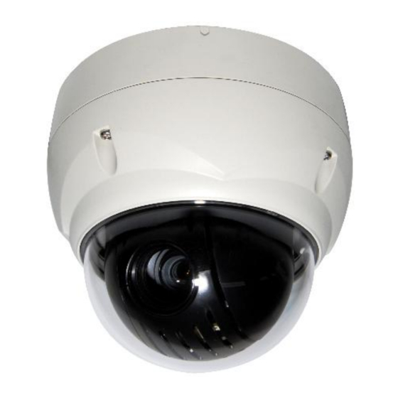
- Page 1 User’s Manual 22X PTZ III NETWORK DOME CAMERA www.hitron.co.kr...
- Page 2 WARNING TO REDUCE THE RISK OF FIRE OR ELECTRIC SHOCK, DO NOT EXPOSE THIS PRODUCT TO RAIN OR MOISTURE. DO NOT INSERT ANY METALLIC OBJECTS THROUGH THE VENTILATION GRILLS OR OTHER OPENINGS ON THE EQUIPMEMT. CAUTION EXPLANATION OF GRAPHICAL SYMBOLS The lightning flash with arrowhead symbol, within an equilateral triangle, is intended to alert the user to the presence of uninsulated “dangerous voltage”...
-
Page 3: Fcc Compliance Statement
FCC COMPLIANCE STATEMENT FCC INFORMATION: THIS EQUIPMENT HAS BEEN TESTED AND FOUND TO COMPLY WITH THE LIMITS FOR A CLASS A DIGITAL DEVICE, PURSUANT TO PART 15 OF THE FCC RULES. THESE LIMITS ARE DESIGNED TO PROVIDE REASONABLE PROTECTION AGAINST HARMFUL INTERFERENCE WHEN THE EQUIPMENT IS OPERATED IN A COMMERCIAL ENVIRONMENT. -
Page 4: Important Safety Instructions
IMPORTANT SAFETY INSTRUCTIONS 1. Read these instructions. 2. Keep these instructions. 3. Heed all warnings. 4. Follow all instructions. 5. Do not use this apparatus near water. 6. Clean only with dry cloth. 7. Do not block any ventilation openings. Install in accordance with the manufacturer’s instructions. -
Page 5: Table Of Contents
Table of Contents Chapter 1 — Introduction......................1 1.1 Features ............................. 1 Chapter 2 — Installation and Configuration ................. 2 2.1 Package Contents..........................2 2.2 Installation ............................3 2.3 Basic Configuration of Dome Camera System ................ 5 2.4 Setting Dome Camera Address (ID) .................... 6 2.5 Connections ............................ - Page 6 4) Audio .......................... 38 5) Date & Time ....................... 39 4.5.2 Video & Image ......................... 40 1) Basic .......................... 40 2) Webcasting – Channel1 .................... 40 4.5.3 Audio ............................41 4.5.4 Event ............................41 1) Event-In ........................41 2) Event-Out ........................45 3) Event Map ........................
-
Page 7: Chapter 1 - Introduction
Chapter 1 — Introduction 1.1 Features The dome camera and the keyboard controller, PC software makes up the building blocks for any surveillance/security system. Using multiple keyboard controllers and multiple dome cameras, no place is too large for monitoring. Extensible and flexible architecture facilitates remote control functions for a variety of external switching devices such as multiplexers and DVRs. -
Page 8: Chapter 2 - Installation And Configuration
Chapter 2 — Installation and Configuration 2.1 Package Contents The dome camera is design to a compact, small size, hard dome camera housing. The housing is constructed of aluminum, steel and plastic. The housing is designed to be mounted both wall and ceiling type. The housing meets the Protection Classification IP66 standards for dust and moisture resistance. -
Page 9: Installation
2.2 Installation The dome camera is for use in surface or pendent mounting applications and the mounting member must be capable of supporting loads of up to 3.5lb (1.6kg). (Pendent mounting must use pendent mount accessory.) The dome camera’s mounting bracket should be attached to a structural object, such as hard wood, wall stud or ceiling rafter that supports the weight of the dome camera. - Page 10 CAUTION: Before installing mounting bracket to surface pre-adjust the four mounting screws "A" on the base of the dome camera to best match the mounting bracket locked position. Unscrew the locking screw on the side of the dome's base and fit the tab of the mounting bracket into the locking slot. Screws "A" should not be too tight or too loose when the dome is in the locked position.
-
Page 11: Basic Configuration Of Dome Camera System
2.3 Basic Configuration of Dome Camera System Wire Color Description Red: 12VDC+ Main Power: 2pin terminal White: 12VDC- Pink, Brown Heater Power(Option): 3pin terminal Black: GND Gray: Alarm Input Yellow: GND Alarm Input/Output, RS485: 6pin terminal Black&White: Alarm Output Green: RS485+ Blue: RS485- Black Ethernet: RJ45 Modular Jack... -
Page 12: Setting Dome Camera Address (Id)
2.4 Setting Dome Camera Address (ID) To prevent damage, each dome camera must have a unique address (ID). When installing multiple dome cameras using a multiplexer, it is suggested that the dome camera address match the multiplexer port number. The factory default setting is 1. Refer to ‘3.13 Dome Communication’... -
Page 13: Ip Assignment
2.6 IP Assignment When the dome camera, encoder or decoder is first connected to the network it has no IP address. So, it is necessary to allocate an IP address to the device with the “SmartManager” utility on the CD. 1. -
Page 14: Getting Started
2.7 Getting Started Once installed apply power to the dome camera. The dome camera will start a configuration sequence. PRESET TITLE AREA TITLE AF AE STATUS of FUNCTION FOCUS and AE UNDER RUNNING CAMERA TITLE EMPTY DATA INFORMATION DISPLAY CAMERA ID DOMEID:0001 W→360.0,090.0 PAN &... -
Page 15: Chapter 3 - Program And Operation
Chapter 3 — Program and Operation 3.1 Dome Camera Selection Before you program or operate a dome camera, you must select the dome camera by pressing No. + CAM keys. Example: Pressing 1 , 0 + CAM keys sequentially will select dome camera 10. The selected dome camera ID will be displayed on the LCD monitor of the keyboard controller. -
Page 16: Auto Scan (Shortcut: Scan)
3.4 Auto Scan (Shortcut: SCAN) The Auto Scan supports up to 5 programmed angles at user-programmable speeds. Follow these steps to program Auto Scan: AUTO SCAN SETUP NUMBER : 01 TITLE : A01 MODE : NORMAL SPEED 5 STEP START ANGLE : ----- ----- END ANGLE : ----- ----- SCAN DIR... - Page 17 6. Select “START ANGLE”. Hold down the CTRL key while selecting the start position using the Joystick. Current panning position will be displayed. Release the CTRL key to complete the selection of the start position. Or press the IRIS Open key then the “CTRL” displays. Move the desired position and the zoom position.
-
Page 18: Preset (Shortcut: Prst)
3.5 Preset (Shortcut: PRST) If you need to view specific places routinely, you should program Presets. A Preset is a programmed video scene with automatic pan, tilt, zoom, focus, and AE settings. Once programmed, placing the number position and pressing the PRST key on your controller calls up that Preset automatically. -
Page 19: Shortcut Of Preset Program
6. Set “DWELL TIME”. (03~99 seconds) 7. To select the next page of Presets, scroll the page by pushing the Joystick to the left on the first and last columns of the menu. 8. Repeat step 2 through 7 for each additional Preset position. 9. -
Page 20: Tour (Shortcut: Tour)
3.7 Tour (Shortcut: TOUR) There are 4 programmable Tours. Each Tour consists of up to 42 Preset positions, Patterns, Scans or other Tours (second-level). Using second-level Tours, it can be expanded to over 150 functions in a single Tour. TOUR SETUP NUMBER TITLE SCAN TYPE... - Page 21 Example: Preset 001>002>003>004>005>006, Auto Scan 01 starts at Preset 002, ends at Preset 003, Auto Scan 02 starts at Preset 005, ends at Preset 006; Tour 001, 002, A01, 004, A02. 1 2 2~3 4 5~6, repeat ...
-
Page 22: Pattern (Shortcut: Ptrn)
3.8 Pattern (Shortcut: PTRN) The Pattern feature records user control of the selected dome camera. Up to 4 Patterns can be stored and played back by pressing No. + PTRN keys subsequently. PATTERN SETUP (CTRL KEY) TITLE PERCENT 01 : 00.0% 02 : 00.0%... -
Page 23: Area Title
3.9 Area Title Enter a specific name on programmed angle between START and END. For the screen below, when the camera points at an angle between 124.3 (PAN), 30.7 (TILT) to 359.5 (PAN), 45.4 (TILT), ABC will be displayed on the screen. AREA TITLE SETUP NUMBER : 01... -
Page 24: Privacy Zone
3.10 Privacy Zone Hide up to 4 unwanted scenes in a camera. PRIVACY ZONE SETUP (CTRL KEY) TITLE METHOD 01 ABC BLOCK 02 DEF V.OFF ---- ---- SAVE AND EXIT(ESC TO CANCEL) 1. Place the cursor at the title field. 2. -
Page 25: Camera Menu
3.11 Camera Menu CAMERA SETUP FOCUS CONTROL WB CONTROL AE CONTROL DNR CONTROL SHARPNESS : 07 RESOLUTION : MID DIGITAL ZOOM : OFF IMAGE FLIP : OFF PRESET FREEZE : OFF SAVE AND EXIT(ESC TO CANCEL) SHARPNESS The higher the value, the more edges in the picture will be enhanced. - Page 26 • WB (White Balance) CONTROL WB SETUP MODE R GAIN B GAIN SAVE AND EXIT(ESC TO CANCEL) MODE AWB / WAWB / INDOOR / OUTDOOR / MANUAL Computes the white balance value output using color information from the entire screen automatically. (2500 to 9500 °K) WAWB Wide range auto white balance mode (1800 to 10500 °K) INDOOR...
- Page 27 The NIGHT SHOT option removes the IR cutoff filter of the camera and makes the camera sensitive to near infrared. AUTO Camera goes in to B&W mode at low light. GLOBAL Controlled by the keyboard (NOTE: GLOBAL function operates F2E protocol only) The operator can enable NIGHT SHOT for all dome cameras at the same time.
-
Page 28: Dome Setup
3.12 Dome Setup CONFIGURATION MENU LANGUAGE : ENGLISH HOME FUNCTION SETUP OSD DISPLAY VIEW ANGLE SETUP INITIALIZE DATA ORIGIN OFFSET DOME RESET SYSTEM MENU SYSTEM INFORMATION SAVE AND EXIT(ESC TO CANCEL) • LANGUAGE SETUP LANGUAGE : Select the language you want. •... - Page 29 • OSD DISPLAY OSD DISPLAY SETUP CAMERA TITLE : DOMEID VIEW DIRECTION : OFF DOME OSD : ON AREA TITLE : OFF PRESET TITLE : CONSTANT FOCUS EXPOSURE : ON OSD POSITION SETUP SAVE AND EXIT(ESC TO CANCEL) CAMERA TITLE : up to 6 characters.
- Page 30 • VIEW ANGLE SETUP VIEW ANGLE SETUP PANNING RANGE FLIP : 90 TILT LIMIT : OFF SAVE AND EXIT(ESC TO CANCEL) FLIP: OFF, AUTO, 90, 100, 110, 120, OFF: the dome camera moves until 90 vertically. AUTO: When the camera reaches the floor directly above the moving object, it will stop. At that time, release the Joystick instantly and pull it down again to run the auto-flip function.
- Page 31 • INITIALIZE DATA INITIALIZE DATA FACTORY DEFAULT ERASE PROGRAMMED DATA PRESET FOCUS DEFAULT EXIT(ESC TO EXIT) FACTORY DEFAULT Select “FACTORY DEFAULT” to initialize the Data. FACTORY DEFAULT ARE YOU SURE ? CANCEL ERASE PROGRAMMED DATA Erase all stored data from the Flash-ROM of the selected dome camera. You will be asked to enter ON or OFF.
- Page 32 • ORIGIN OFFSET OFFSET SETUP (CTRL KEY) PAN OFFSET : 000.0 TILT OFFSET : 000.0 ENABLE : OFF SAVE AND EXIT(ESC TO CANCEL) This feature is useful to align a new dome camera exactly the same as the previously installed dome camera.
- Page 33 MOTOR SETUP Motor Setup menu provides the pan and tilt speed of a camera. User can set the desired speed with pushing the Joystick to the left or right. During operation, pressing 153 + ON keys will change the speed to the SLOW mode and pressing 153 + OFF keys will change the speed to the Normal mode.
-
Page 34: Dome Communication
• SYSTEM INFORMATION SYSTEM INFORMATION CAMERA TYPE : xxxxx-xxxxxx H/W VERSION : Vx.xx ROM VERSION : Vx.xx PROTOCOL : xxxx BAUDRATE : 9600 EXIT(ESC TO EXIT) The system information provides essential information about the dome camera if service is required. When you view this screen, you can determine the camera type, ROM version. The information on this screen cannot be modified. -
Page 35: Function Run
3.14 Function Run This Function Run menu allows you to execute the function when you use a keyboard or a DVR without the function keys (Preset, Pattern, Tour and Scan). FUNCTION RUN SETUP (CTRL KEY) PRESET : --- PATTERN : --- TOUR : --- SCAN... -
Page 36: Chapter 4 - Operation By Web Browser
Chapter 4 — Operation by Web Browser The network camera can be used with Windows operating system and browsers. The recommended browsers are Internet Explorer, Safari, Firefox, Opera and Google Chrome with Windows. Note: To view streaming video in Microsoft Internet Explorer, set your browser to allow ActiveX controls. -
Page 37: Access From The Internet
4.2 Access from the internet Access from the internet once connected, the network camera is accessible on your local network (LAN). To access the video encoder from the Internet you must configure your broadband router to allow incoming data traffic to the video encoder. To do this, enable the NAT traversal feature, which will attempt to automatically configure the router to allow access to the video encoder. - Page 38 1) General controls The video drop-down list allows you to select a customized or pre- programmed video stream on the live view page. Stream profiles are configured under Setup > Basic Configuration > Video & Image. Please see “4.5.1 Basic Configuration” for more information. The resolution drop-down list allows you to select the most suitable one out of video resolutions to be displayed on live view page.
-
Page 39: Network Camera Setup
The PTZ button activates a pop-up window for Pan, Tilt and Zoom control. Use this scale to control the volume of the speakers. Use this scale to control the volume of the microphone. Use this scale to control the volume of the speakers and microphones. 3) Camera Menu controls If the network camera has been appropriately configured, the Live View page displays the controls available for the OSD menu. -
Page 40: Basic Configuration
When accessing the network camera for the first time, the “Admin Password” dialog appears. Enter your admin name and password, set by the administrator. Note: If the password is lost, the network camera must be reset to the factory default settings. Please see “4.8 Resetting to the Factory Default Settings”. -
Page 41: Network
2) Network The network camera support both IP version 4 and IP version 6. Both versions may be enabled simultaneously, and at least one version must always be enabled. When using IPv4, the IP address for the video encoder can be set automatically via DHCP, or a static IP address can be set manually. -
Page 42: Video & Image
3) Video & Image • Video Setting: - Codec: The codec settings are separated into MPEG4 and H.264. H.264 is also known as MPEG-4 Part 10. This is the new generation compression standard for digital video. This function offers higher video resolution than Motion JPEG or MPEG-4 at the same bit rate and bandwidth, or the same quality video at a lower bit rate. - Page 43 - Bitrate control: Limiting the maximum bit rate helps control the bandwidth used by the H.264 or MPEG-4 video stream. Leaving the Maximum bit rate as unlimited maintains consistently good image quality but increases bandwidth usage when there is more activity in the image.
-
Page 44: Audio
4) Audio The network camera can transmit audio to other clients using an external microphone and can play audio received from other clients by attaching a speaker. The Setup page has an additional menu item called Audio, which allows different audio configurations, such as, full duplex, and simplex. -
Page 45: Date & Time
- Output volume: If the sound from the speaker is too low or high it is possible to adjust the output gain for the active speaker attached to the network camera. When satisfied with the settings, click Save, or click Reset to revert to previously saved settings. -
Page 46: Video & Image
4.5.2 Video & Image 1) Basic Refer to “4.5.1 Basic Configuration > 3) Video & Image” for more details. 2) Webcasting – Channel1 The network camera can stream live video to a website. Copy the HTML code generated on the screen and paste it in page code of the website you want to display live video. Note: To use webcasting service, the Enable Anonymous viewer login option must be checked. -
Page 47: Audio
4.5.3 Audio Refer to “4.5.1 Basic Configuration > 4) Audio” for more details. 4.5.4 Event 1) Event-In ① On Boot This is used to trigger the event every time the Network Transmitter is started. Select “Enable” to activate the motion event. - Page 48 ② Alarm In Select “Enable” to activate the alarm event. The network camera support 1 alarm input ports. - Type: Choose the type of alarm you wish to use from the drop-down list. - Dwell Time: Set the dwell time an event lasts for the specified dwell time from the point of detection of an alarm input.
- Page 49 ④ Motion Motion detection is used to generate an alarm whenever movement occurs (or stops) in the video image. A total of 8 Motion and/or Mask windows can be created and configured. Motion is detected in defined Motion windows, which are placed in the video image to target specific areas.
- Page 50 • Motion Detection Setting: The behavior for each window is defined by adjusting the Threshold and Sensitivity, as described below. A motion index is a set of parameters describing Window Name, Type, Threshold, Sensitivity, and Dwell Time. Window Types is one of Motion and Mask windows. - Threshold: Sets up the sensitivity for the motion detection.
-
Page 51: Event-Out
2) Event-Out ① SMTP(E-Mail) The network camera can be configured to send event and error email messages via SMTP (Simple Mail Transfer Protocol). • SMTP(E-Mail) Setting: Select “Enable” to activate the SMTP operation. - Mail Server / Port: Enter the host names (or IP addresses) and port numbers for your mail server in the fields provided, to enable the sending of notifications and image email messages from the camera to predefined addresses via SMTP. - Page 52 • SMTP(E-Mail) Receiver: - Receiver: Enter an email address. You can also register the e-mail address of recipients up to 8. • SMTP(E-Mail) Test: - Receiver: Enter an email address and click the Test button to test that the mail servers are functioning and that the email address is valid.
-
Page 53: Http Server
• JPEG Setting: - Pre-event: A pre-event buffer contains images from the time immediately preceding the event trigger. These are stored internally in the server. This buffer can be very useful when checking to see what happened to cause the event trigger. Check the box to enable the pre-trigger buffer, enter the desired total length in seconds, minutes or hours, and specify the required image frequency. -
Page 54: Alarm Out
④ Alarm Out When the network camera detects an event, it can control external equipment connected to its alarm output port. Check the box to enable and then select either: - Enable: When you select “Enable alarm out”, the output will be activated for as long as the event is active. - Page 55 • Audio Alert Setting: To use the audio alert with the Network Transmitter, an audio data file made by user must be uploaded from your PC. Provide the path to the file directly, or use the Browse button to locate it. Then click the Upload button. An audio file for Audio Alert can be made by Audio Recorder tool in the NautilusClient16 software.
- Page 56 The description of each button in the ARecorder window follows. Open: Open an audio file. Capture: Capture audio from the microphone in your PC. Save: Save a captured file to your PC. (PCM format) Encode: Encode a current capture file or opened PCM file to G.726 file for Audio Alert.
-
Page 57: Event Map
⑦ PTZ Preset When the Network Transmitter detects an event, you can make a PTZ camera connected to its RS485 port to move to a predefined preset position. Check the box to enable the service and return to the Home position once the event has ended. 3) Event Map The event map allows you to change the settings and establish a schedule for each event trigger from the network camera. - Page 58 • General: Enter the name for a new event map. • Event In: Select an event type in the drop down list. • Event Out: - E-mail: Select email addresses you want to send via email that an event has occurred. - FTP: Select checkbox beside FTP to record and saves images to an FTP server when an event has occurred.
-
Page 59: System
4.5.5 System 1) Information You can enter the system information. This page is very useful when you refer device information after installation. • Device Name Configuration: Enter the device name. • Location Configuration: Enter the location information. You can enter that by four. 2) Security ①... - Page 60 User access control is enabled by default, when the administrator sets the root password on first access. New users are authorized with user names and passwords, or the administrator can choose to allow anonymous viewer login to the Live View page, as described below: •...
- Page 61 • HTTPS Connection Policy: Choose the form of connection you wish to use from the drop-down list for the administrator, Operator and Viewer to enable HTTPS connection (set to HTTP by default). - HTTP - HTTPS - HTTP & HTTPS •...
-
Page 62: Date & Time
3) Date & Time • Current Server Time: It displays the current date and time (24h clock). The time can be displayed in 12h clock format in the overlay (see below). • New Server Time: Select your time zone from the drop-down list. If you want the server clock to automatically adjust for daylight savings time, select “Automatically adjustment for daylight saving time changes”. -
Page 63: Network
4) Network Setting in regard to network can be executed. Settings for IP, DNS, Host Name, Port, and ARP/Ping can be established, along with setting for DDNS, uPnP, QoS, and SNMP. ① Basic • IP Address Configuration: - Obtain IP address via DHCP: Dynamic Host Configuration Protocol (DHCP) is a protocol that lets network administrators centrally manage and automate the assignment of IP addresses on a network. - Page 64 • IPv6 Address Configuration: Check this box to enable IPv6. Other settings for IPv6 are configured in the network router. • DNS Configuration: DNS (Domain Name Service) provides the translation of host names to IP addresses on your network. - Obtain DNS Server via DHCP: Automatically use the DNS server settings provided by the DHCP server.
- Page 65 ② DDNS • Internet DDNS(Dynamic Domain Name Service): When using the high-speed Internet with the telephone or cable network, users can operate the network camera even on the floating IP environment in which IPs are changed at every access. Users should receive an account and password by visiting a DDNS service like http://www.dyndns.com/ or http://www.cctv-network.co.kr/.
- Page 66 ③ RTP Have a setting for sending and receiving an audio or video on a real-time basis. These settings are the IP address, port number, and Time-To-Live value to use for the media stream(s) in multicast H.264 format. Only certain IP addresses and port numbers should be used for multicast streams.
- Page 67 ④ UPnP The network camera includes support for UPnP™. UPnP™ is enabled by default, and the network camera then is automatically detected by operating systems and clients that support this protocol. Note: UPnP™ must be installed on your workstation if running Windows XP. To do this, open the Control Panel from the Start Menu and select Add/Remove Programs.
- Page 68 ⑤ QoS Quality of Service (QoS) provides the means to guarantee a certain level of a specified resource to selected traffic on a network. Quality can be defined as a maintained level of bandwidth, low latency, and no packet losses. The main benefits of a QoS-aware network are: - The ability to prioritize traffic and thus allow critical flows to be served before flows with lesser priority.
- Page 69 ⑥ NAT Traversal A broadband router allows devices on a private network (LAN) to share a single connection to the Internet. This is done by forwarding network traffic from the private network to the “outside”, that is, the Internet. Security on the private network (LAN) is increased since most broadband routers are pre-configured to stop attempts to access the private network (LAN) from the public network/Internet.
-
Page 70: Language
• NAT traversal Settings: - Enable: when enabled, the Network Transmitters attempt to configure port mapping in a NAT router on your network, using UPnP™. Note that UPnP™ must be enabled in the network camera. (Please see Setup > System > Network > UPnP, on “4.5.5 System >... -
Page 71: Support
- the boot protocol (DHCP or static) - the static IP address - the default router - the subnet mask - the system time - Default: The default button should be used with caution. Pressing this will return all of the network camera's settings to the factory default values (including the IP address). -
Page 72: About
4.5.6 About The following website will provide the support information for the network camera information and operation. 4.6 PTZ Control You can control a PTZ in the live screen. Press the button on the left top in the live screen to activate the PTZ control panel. -
Page 73: Help
- Up/Down button: Navigate through the menu items - PAN/TILT Speed: It sets a speed when adjusting the PTZ Camera. The higher a value is, the faster a speed will be. - Focus: Overrides auto focus. Moving the Zoom handle reactivates Auto Focus mode. - Iris: Overrides auto iris. -
Page 74: Resetting To The Factory Default Settings
4.8 Resetting to the factory default settings To reset the network camera to the original factory settings, go to the Setup > System > Maintenance web page or use the control button on the network camera, as described below: • Using the Reset Button Follow the instructions below to reset the network camera to the factory default settings using the Reset Button. -
Page 75: Appendix A - Specifications
Appendix A — Specifications 22X Optical Zoom PTZ III Network Dome System MODEL MODULE CCD Type 1/4" Type EXview HAD CCD Optical / Digital Zoom 22X / 16X Resolution 580 TVL Focal length f = 3.9mm ~ 85.8mm 3.9mm – 49.5° (H) Angle of view 85.8mm –... - Page 76 NETWORK Motion JPEG MPEG-4 Part2 Video Compression H.264 (MPEG-4 Part 10) Profiles: H.264 MP and BP, MPEG-4 ASP and SP 160X120 ~ 704X480 : NTSC Video Resolutions 160X120 ~ 704X576 : PAL Frame Rate Up to 30/25fps[NTSC/PAL] @ all resolutions Simultaneously H.264(or MPEG-4) and MJPEG Video Streaming Controllable Frame Rate and Bandwidth VBR/CBR H.264 and...
- Page 77 Figure – Dimension...
-
Page 78: Appendix B - Troubleshooting
Appendix B — Troubleshooting If problems occur, verify the installation of the camera with the instructions in this manual and with other operating equipment. Isolate the problem to the specific piece of equipment in the system and refer to the equipment manual for further information. Problem Possible Solution Verify that power is connected to all pieces of... -
Page 79: Home Position
Automatic Gain Control (AGC) Allows for the amplification of the video signal in scenes with minimal ambient light. Many low- light scenes result in picture noise. As gain is increased, the picture noise is also amplified. When AGC is enabled, the value of the gain setting is based on feedback from the camera. When AGC is disabled, the camera uses the value set for the manual gain setting. -
Page 80: White Balance
North Position User-definable setting that may correspond to magnetic north or some well-known landmark. Used to approximate the camera dome's pointing direction when Direction Indicators are enabled. Slow Shutter Setting used to improve the quality of video obtained in extreme low-light situations. When the Low Shutter setting is enabled, low-light information is collected over multiple fields based on the Shutter Limit setting. -
Page 81: Appendix D - Short Cut Key
Appendix D — Short Cut Key Short Cut Key Function PRST Pop up Preset setup menu. TOUR Pop up Tour setup menu. PTRN Pop up Pattern setup menu. SCAN Pop up Auto Scan setup menu. No.+ CTRL+ PRST Store the current view at the selected number. Short Cut Key Function Short Cut Key... - Page 82 Videor E. Hartig GmbH ® Exclusive distribution through specialised trade channels only. Videor E. Hartig GmbH Carl-Zeiss-Straße 8 · 63322 Rödermark, Germany Tel. +49 (0) 6074 / 888-0 · Fax +49 (0) 6074 / 888-100 www.videor.com...
Need help?
Do you have a question about the 22X and is the answer not in the manual?
Questions and answers