Table of Contents
Advertisement
Quick Links
Advertisement
Table of Contents

Related Manuals for Eneo Minitrax HDD-1012PTZ1080


Summary of Contents for Eneo Minitrax HDD-1012PTZ1080
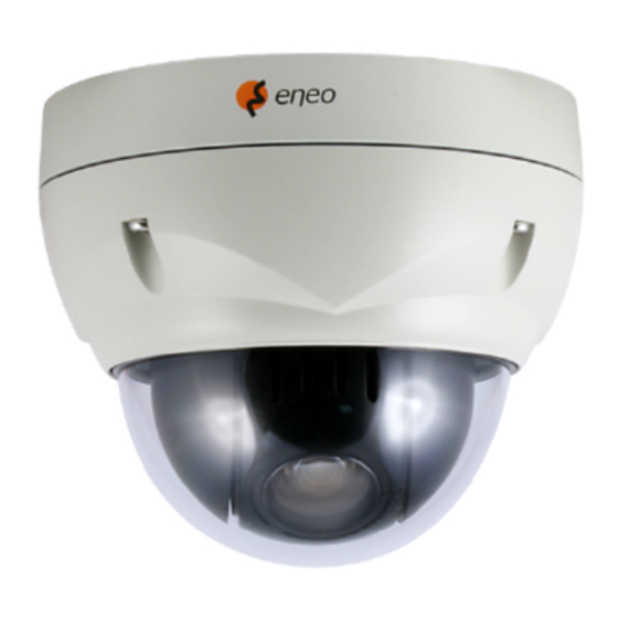
- Page 1 Full Manual Minitrax 1/2.8" Day/Night Dome Camera, PTZ HDD-1012PTZ1080...
- Page 2 WARNING TO REDUCE THE RISK OF FIRE OR ELECTRIC SHOCK, DO NOT EXPOSE THIS PRODUCT TO RAIN OR MOISTURE. DO NOT INSERT ANY METALLIC OBJECTS THROUGH THE VENTILATION GRILLS OR OTHER OPENINGS ON THE EQUIPMENT. CAUTION CAUTION RISK OF ELECTRIC SHOCK DO NOT OPEN CAUTION: TO REDUCE THE RISK OF ELECTRIC SHOCK, DO NOT REMOVE COVER (OR BACK)
- Page 3 CE COMPLIANCE STATEMENT WARNING This is a Class A product. In a domestic environment this product may cause radio interference in which case the user may be required to take adequate measures.
-
Page 4: Important Safety Instructions
IMPORTANT SAFETY INSTRUCTIONS Read these instructions. Keep these instructions. Heed all warnings. Follow all instructions. Do not use this apparatus near water. Clean only with dry cloth. Do not block any ventilation openings. Install in accordance with the manufacturer’s instructions. Do not install near any heat sources such as radiators, heat registers, stoves, or other apparatus (including amplifiers) that produce heat. -
Page 5: Table Of Contents
Table of Contents Chapter 1 — Introduction ....................1 1.1 Features ..........................1 Chapter 2 — Installation and Configuration ..............2 2.1 Package Contents ......................2 2.2 Installation ........................3 2.3 Basic Configuration of Dome Camera System ............... 6 2.4 Setting Dome Camera Address (ID) ................7 2.5 Connections ........................ -
Page 6: Chapter 1 - Introduction
Chapter 1 — Introduction 1.1 Features The dome camera and the keyboard controller make up the building blocks for any surveillance/security system. Using multiple keyboard controllers and multiple dome cameras, no place is too large for monitoring. Extensible and flexible architecture facilitates remote control functions for a variety of external switching devices such as multiplexers and DVRs. -
Page 7: Chapter 2 - Installation And Configuration
Chapter 2 — Installation and Configuration 2.1 Package Contents The dome camera is designed with compact, small size, hard dome camera housing. The housing is constructed of aluminum, steel and plastic. The housing is designed to be mounted on a wall or a ceiling. The housing meets the Protection Classification IP66 standards for dust and moisture resistance. -
Page 8: Installation
2.2 Installation The dome camera is for use in surface or pendent mounting applications, and the mounting member must be capable of supporting loads of up to 4.4 lb (2.0 kg). (Pendent mounting must use pendent mount accessory.) The dome camera’s mounting bracket should be attached to a structural object, such as hard wood, wall stud or ceiling rafter that supports the weight of the dome camera. - Page 9 CAUTION: Before installing mounting bracket to surface pre-adjust the four mounting screws "A" on the base of the dome camera to best match the mounting bracket locked position. Unscrew the locking screw on the side of the dome's base and fit the tab of the mounting bracket into the locking slot. Screws "A" should not be too tight or too loose when the dome is in the locked position.
- Page 10 2.2.2 Heater Kit Installation 1. Assemble the Heater board to two bossed with screws. Take a reference "B" in the bottom case as below. 2. Place the Heater in the slot "A". Heater cable should be placed away from the Main board. 3.
-
Page 11: Basic Configuration Of Dome Camera System
2.3 Basic Configuration of Dome Camera System Connector Wire Color Description 24VAC or 12VDC+ 3-pin terminal block WHITE 24VAC or 12VDC- GREEN RS-485+ 2-pin terminal block BLUE RS-485- GRAY ALARM INPUT 1 VIOLET ALARM INPUT 2 5-pin terminal block ORANGE ALARM INPUT 3 SKY BLUE ALARM INPUT 4... -
Page 12: Setting Dome Camera Address (Id)
2.4 Setting Dome Camera Address (ID) To prevent damage, each dome camera must have a unique address (ID). The factory default setting is 1. Refer to ‘3.11 Dome Communication’ section for detailed information. 2.5 Connections • Connecting to the RS-485 The dome camera can be controlled remotely by an external device or control system, such as a control keyboard, using RS-485 half-duplex serial communications signals. -
Page 13: Getting Started
2.6 Getting Started Once installed apply power to the dome camera. The dome camera will start a configuration sequence. STATUS of AF AE FUNCTION TITLE FOCUS and AE INFORMATION EMPTY DATA DISPLAY ALARM:1 ALARM DISPLAY DOMEID:0001 CAMERA TITLE & ID 360.0 090.0 PAN &... -
Page 14: Chapter 3 - Program And Operation
Chapter 3 — Program and Operation 3.1 Dome Camera Selection Before you program or operate a dome camera, you must select the dome camera by pressing No. + CAM keys. Example: Pressing 1 , 0 + CAM keys sequentially will select dome camera 10. The selected dome camera ID will be displayed on the LCD monitor of the keyboard controller. -
Page 15: Auto Scan (Shortcut: Scan)
3.4 Auto Scan (Shortcut: SCAN) The Auto Scan supports up to 17 programmed angles at user-programmable speeds. Follow these steps to program Auto Scan: AUTO SCAN SETUP NUMBER : 01 TITLE : A01 MODE : NORMAL SPEED 5 STEP START ANGLE : ----- ----- END ANGLE : ----- -----... - Page 16 5. Select “MODE” and “SPEED”. 6. Select “START ANGLE”. Hold down the CTRL key while selecting the start position using the Joystick. Current panning position will be displayed. Release the CTRL key to complete the selection of the start position. Or press the IRIS Open key then the “CONTROL” displays. Move the desired position and the zoom position.
-
Page 17: Preset (Shortcut: Prst)
3.5 Preset (Shortcut: PRST) If you need to view specific places routinely, you should program Presets. A Preset is a programmed video scene with automatic pan, tilt, zoom, focus, and AE settings. Once programmed, placing the number position and pressing the PRST key on your controller calls up that Preset automatically. -
Page 18: Shortcut Of Preset Program
Select “AE SETUP” and push the Joystick to the left or right. Then the AE setup displays. Refer to the AE SETUP in the camera setup. 6. Set “DWELL time”. (03 ~ 99 seconds) 7. To select the next page of Presets, scroll the page by pushing the Joystick to the left or right on the first or last columns of the menu. -
Page 19: Tour (Shortcut: Tour)
3.7 Tour (Shortcut: TOUR) There are 8 programmable Tours. Each Tour consists of up to 42 Preset positions, Patterns, Scans or other Tours (second-level). Using second-level Tours, it can be expanded to over 300 functions in a single Tour. TOUR SETUP NUMBER : 01 TITLE... - Page 20 9. Select “SAVE AND EXIT” and push the Joystick to the right or press the IRIS Open key. Press the ESC or IRIS Close key to exit the program without saving. You can expand the Tour sequence by calling other programmed Tours. NOTE: The speed applies in the vector mode only.
-
Page 21: Pattern (Shortcut: Ptrn)
3.8 Pattern (Shortcut: PTRN) The Pattern feature records user control of the selected dome camera. Up to 8 Patterns can be stored and played back by pressing No. + PTRN keys subsequently. PATTERN SETUP (CTRL KEY) TITLE PERCENT 00.0% 00.0% 00.0% 00.0% 00.0%... -
Page 22: Privacy Zone
3.9 Privacy Zone Hide up to 8 unwanted scenes in a camera. There are two pages of Privacy Zone menu. Each page has 4 Privacy Zones. PRIVACY ZONE SETUP (CTRL KEY) METHOD COLOR BLOCK GRAY BLOCK GRAY ----- GRAY ----- GRAY NEXT PAGE SAVE AND EXIT(ESC TO CANCEL) -
Page 23: Camera Menu
3.10 Camera Menu CAMERA SETUP FOCUS CONTROL WB CONTROL AE CONTROL CAMERA CONTROL SHARPNESS : 01 IMAGE FLIP : OFF RESOLUTION : 1080P/25 SAVE AND EXIT(ESC TO CANCEL) SHARPNESS The higher the value, the more edges in the picture will be enhanced. - Page 24 • WB (White Balance) CONTROL WB SETUP MODE : AUTO R GAIN : 012 B GAIN : 019 SAVE AND EXIT(ESC TO CANCEL) MODE AUTO, WAWB, MANUAL, INDOOR, OUTDOOR, FLUORESCENT, SODIUM LAMP AUTO Computes the white balance value output using color information from the entire screen automatically.
- Page 25 The NIGHT SHOT option removes the IR cutoff filter of the camera and makes the camera sensitive to near infrared. AUTO Camera goes in to B&W mode at low light. GLOBAL Controlled by the keyboard (NOTE: GLOBAL function operates F2E protocol only) The operator can enable NIGHT SHOT for all dome cameras at the same time.
-
Page 26: Dome Communication
3.11 Dome Communication To prevent damage, each dome camera must have a unique address (ID). The factory default setting is 1. DOME COMMUNICATION DOME ID : 0001 PROTOCOL : AUTO BAUDRATE : 9600 PARITY : NONE TERMINATION : OFF SAVE AND EXIT(ESC TO CANCEL) DOME ID 1 ~ 3999 PROTOCOL... -
Page 27: Alarm
3.12 Alarm ALARM SETUP (CTRL KEY) NO PRI FUN IN LATCH 001 NO OUT1 03 --- OFF --- OFF --- OFF DWELL : 03 SEC ALARM OUT SETUP SAVE AND EXIT(ESC TO CANCEL) NO (Number) alarm input number PRI (Priority) the lower number has higher priority (0 ~ 4) FUN (Function) Stored function number to be called by alarm. -
Page 28: Dome Setup
3.13 Dome Setup CONFIGURATION MENU HOME FUNCTION SETUP VIEW ANGLE SETUP ORIGIN OFFSET FACTORY DEFAULT DOME RESET OSD DISPLAY SYSTEM SETUP FUNCTION RUN SYSTEM INFORMATION EXIT(ESC TO EXIT) • HOME FUNCTION SETUP HOME FUNCTION SETUP FUNCTION : NONE NUMBER : --- WAITING TIME : 120 SEC ENABLE... - Page 29 • VIEW ANGLE SETUP VIEW ANGLE SETUP PANNING RANGE FLIP : 90° TILT ANGLE LIMIT : 00° SAVE AND EXIT(ESC TO CANCEL) FLIP: OFF, AUTO, 90°, 100°, 110°, 120° OFF: The dome camera moves until 90° vertically. AUTO: When the camera reaches the floor directly above the moving object, it will stop. At that time, release the Joystick instantly and pull it down again to run the auto-flip function.
- Page 30 • ORIGIN OFFSET OFFSET SETUP (CTRL KEY) PAN OFFSET : 000.0 TILT OFFSET : 000.0 ENABLE : OFF SAVE AND EXIT(ESC TO CANCEL) This feature is useful to align a new dome camera exactly the same as the previously installed dome camera.
- Page 31 • OSD DISPLAY OSD DISPLAY SETUP LANQUAGE : ENGLISH TITLE : DOMEID DOME OSD : ON FOCUS/EXPOSURE : OFF COLOR : YELLOW SAVE AND EXIT(ESC TO CANCEL) LANGUAGE Select the desired language. TITLE up to 6 characters DOME OSD ON, OFF All display or title will disappear when DOME OSD DISPLAY is set to OFF.
- Page 32 MOTOR SETUP Motor Setup menu provides the pan and tilt speed of a camera. User can set the desired speed with pushing the Joystick to the left or right. During operation, pressing 153 + ON keys will change the speed to the SLOW mode and pressing 153 + OFF keys will change the speed to the NORMAL mode.
- Page 33 ORIGIN CHECK If you find the dome in the wrong position during operation, execute this origin check and the dome camera will return to the right position after the origin check operation. ORIGIN CHECK ARE YOU SURE ? CANCEL Pressing 151 + ON keys will execute the origin check. •...
- Page 34 ALARM OUT SETUP OUT1 : ALARM OUT2 : 1 MIN EXIT(ESC TO EXIT) You press the CTRL or IRIS Open key then that alarm out operates during the setting time only. • SYSTEM INFORMATION SYSTEM INFORMATION CAMERA TYPE : xxxx-Vx.xx H/W VERSION : Vx.xx ROM VERSION...
-
Page 35: Appendix A - Specifications
Appendix A — Specifications 12x Full HD Megapixel HD-SDI Speed Dome Camera MODEL MODULE Image Sensor 1/2.8" SONY Exmor CMOS Scanning Mode Progressive Scan Optical Zoom Resolution 1920 x 1280 Focal Length f = 4.8mm ~ 57.6mm 4.8mm – 64.2° (H) Angle of View 57.6mm –... - Page 36 Figure – Dimension...
-
Page 37: Appendix B - Troubleshooting
Appendix B — Troubleshooting If problems occur, verify the installation of the camera with the instructions in this manual and with other operating equipment. Isolate the problem to the specific piece of equipment in the system and refer to the equipment manual for further information. Problem Possible Solution Verify that power is connected to all pieces of... -
Page 38: Appendix C - Fastrax Protocol
Appendix C — Fastrax Protocol Short Cut Key Function PRST Pop up Preset setup menu TOUR Pop up Tour setup menu PTRN Pop up Pattern setup menu SCAN Pop up Auto Scan setup menu No.+ CTRL+ PRST Store the current view at the selected number Short Cut Key Function Short Cut Key... - Page 40 Videor E. Hartig GmbH Exclusive distribution through specialised trade chan- nels only. Videor E. Hartig GmbH Carl-Zeiss-Straße 8 · 63322 Rödermark/Germany Tel. +49 (0) 6074 / 888-0 · Fax +49 (0) 6074 / 888- Technical changes reserved www.videor.com...
Need help?
Do you have a question about the Minitrax HDD-1012PTZ1080 and is the answer not in the manual?
Questions and answers