
Related Manuals for SATO HR2 Series


Summary of Contents for SATO HR2 Series
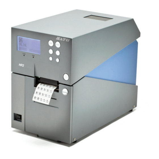
- Page 1 Operator Manual For printer model: HR2 Series Read this Operator Manual before using this product. Keep this document available for future reference.
- Page 2 Specifications and contents in this document are subject to change without notice. Trademarks SATO is a registered trademark of SATO Corporation and its subsidiaries in Japan, the U.S. and other countries. All other trademarks are the property of their respective owners.
- Page 3 Doing so could from the outlet, and contact fire or electric shock. result in fire or electric shock. your SATO reseller or Contact your SATO reseller or technical support center. technical support center to Using the printer in this conduct internal inspections, condition could cause a fire or adjustments, and repairs.
-
Page 4: Safety Precautions
• When maintaining and pinched under the printer feet. not slip off and drop. cleaning the printer, unplug the power cord from the outlet to maintain safety Page ii HR2 Series Operator Manual... -
Page 5: Power Supply
Precautions for Installation and Handling Printer operation can be affected by the printer environment. Refer to the following instructions for installation and handling of HR2 Series printer. Select a Safe Location Do not place the printer in a location subject to water or oil. -
Page 6: Table Of Contents
3.12 Received Data Saving Mode................... 3 - 35 3.13 Test Print Mode ....................... 3 - 36 3.13.1 Types of Test Print..................3 - 39 3.13.2 Explanation of the contents of each piece of Factory Test Print 1....3 - 39 Page iv HR2 Series Operator Manual... - Page 7 7.3 Universal Serial Bus (USB) Interface ................7 - 5 7.3.1 Basic Specifications ..................7 - 5 7.3.2 Pin Assignments ....................7 - 5 7.4 Local Area Network (LAN) Ethernet ................7 - 6 7.4.1 Basic Specifications ..................7 - 6 HR2 Series Operator Manual Page v...
- Page 8 8.5.1 Paper End Detection during Paper Feed ............8 - 8 8.5.2 Paper end detection in print motion ..............8 - 8 8.6 Ribbon End........................ 8 - 10 8.7 Rewinder Full ......................8 - 11 Page vi HR2 Series Operator Manual...
-
Page 9: Introduction
Section 1: Introduction INTRODUCTION Thank you for your investment in this SATO printer product. This Operator Manual contains the basic information about the installation, setup, configuration, operation and maintenance of the printer. A total of eight topics are covered herein, and they are organized as follows:... -
Page 10: Features Of The Printer
5. Set the printer on a solid, flat surface. Inspect the shipping container and printer for any sign of damage that may have occurred during shipping. Please note that SATO shall hold no liability of any damage of any kind sustained during shipping of the product. -
Page 11: Parts Identification
Press this switch to turn the power on (I) or OPEN button off (O). Press this button to open the Top cover. Dispenser unit open button Slide this button downwards to open the cover of the Dispenser unit. HR2 Series Operator Manual Page 1-3... -
Page 12: Back View
To connect printer to the host computer using AC IN power terminal the RS232C serial interface. Supplies power to the printer by inserting the Or, to connect to the optional SATO keypad. power cable. External connector terminal (EXT) Before connection, ensure that the AC voltage Interface connector for external signals. - Page 13 To insert SD card for additional memory up to 2 GB. Used to pinch the roll media. Dispenser unit Guide roller A unit to peel off label automatically after Roller to guide the roll media. printing. HR2 Series Operator Manual Page 1-5...
- Page 14 Ribbon pinch lever Used to pinch the ribbon. Ribbon supply shaft bearing To hold the Ribbon supply shaft. Ribbon unit A unit for loading ribbon. Ribbon rewind shaft bearing To hold the Ribbon rewind shaft. Page 1-6 HR2 Series Operator Manual...
- Page 15 Used to guide the label. Used to lock the roll media guide. Platen roller Roll media guide Enable smooth movement of the label during Set to meet the size of the media used. printing. HR2 Series Operator Manual Page 1-7...
- Page 16 Decrement value in various modes. LINE button Arrow buttons Press this button to toggle between printer Press to move the cursor left or right in various modes or go back to previous setting in various modes. modes Page 1-8 HR2 Series Operator Manual...
-
Page 17: Installation
2.2 Media Selection • 2.3 Loading Media • 2.4 Loading the Carbon Ribbon • 2.5 Removing the Carbon Ribbon • 2.6 Basic Connections • 2.7 Connections of optional accessories • 2.8 LCD Power Saving Mode HR2 Series Operator Manual Page 2-1... -
Page 18: Site Location
For optimal print performance and durability, please use SATO-certified media and ribbon supplies on this printer. Using supplies not tested and approved for use by SATO can result in unnecessary wear and damage to vital parts of the printer, and may void the warranty. -
Page 19: Loading Media
Make sure that the cover rests firmly so that it will not fall forward and injure your hands. OPEN button Dispenser unit open button Attach the supplied roll holders to the left and right sides of the roll media respectively. Outer side Inner side HR2 Series Operator Manual Page 2-3... - Page 20 Label guide Notes: Make sure the media leader is pulled out from the top and the printed side is facing upwards. Push the roll firmly towards the end of the roll shaft bearing. Page 2-4 HR2 Series Operator Manual...
- Page 21 Push the rewinder onto the rewinder shaft bearing until you hear a “tick” sound. Rewinder gear Rewinder core Turn the rewinder until the label to be printed reaches the platen roller. Platen roller Dispenser plate HR2 Series Operator Manual Page 2-5...
- Page 22 When replacing media, bear in mind that the print head and its surrounding area remain hot. Keep your fingers away from these areas to prevent injury. • Avoid touching even the edge of the print head with your bare hands. Page 2-6 HR2 Series Operator Manual...
-
Page 23: When Operating In Continuous Mode For The First Time
Lift up the Top cover while holding down the OPEN button. OPEN button Load the media. (Refer to steps 2~5 of Section 2.3.1 To load the label when using the dispenser) Close the top cover. HR2 Series Operator Manual Page 2-7... -
Page 24: Overview Of The Media/ Ribbon Loading Path
2.3 LOADING MEDIA (cont’d) 2.3.4 Overview of the media/ ribbon loading path Note: You may also refer to the sticker pasted on the inner side of the top cover for the media/ ribbon loading path. Page 2-8 HR2 Series Operator Manual... -
Page 25: Loading The Carbon Ribbon
2.4 LOADING THE CARBON RIBBON The HR2 series printer enables Thermal transfer printing. Thermal transfer paper media requires the use of carbon ribbon for print application. In such a scenario, it is the carbon ribbon that contains the ink that will be transferred to the media. - Page 26 Hold two corners of the pinch roller unit and pull it in the arrow direction to unlatch. Pinch roller unit Lift down the ribbon unit and push the ribbon pinch lever upwards. Ribbon pinch lever Page 2-10 HR2 Series Operator Manual...
- Page 27 Align to the cross-shape shaft bearing when Align to the round shape shaft bearing latching the ribbon. when latching the ribbon. Note: Use only genuine SATO carbon ribbons for maximum print quality and printer durability. HR2 Series Operator Manual Page 2-11...
- Page 28 Ribbon core. Paste the leader portion of the carbon ribbon onto the pinch lever ribbon rewind core. Ribbon roller Right side view Print head Pinch roller unit Page 2-12 HR2 Series Operator Manual...
- Page 29 Lift down the ribbon pinch lever back to the ribbon roller position. Ribbon pinch lever Lift up the ribbon unit and remount the pinch roller unit. Latch the pinch roller unit until you hear a “tick” sound. Ribbon unit Pinch roller unit HR2 Series Operator Manual Page 2-13...
- Page 30 See Section 3.12 Received Data Saving Mode for instructions on how to run test print Page 2-14 HR2 Series Operator Manual...
-
Page 31: Removing The Carbon Ribbon
With the power supply is off, lift up the top cover and release the ribbon unit by pressing the ribbon lever. Ribbon unit lever Hold two corners of the pinch roller unit to unlatch it. Lift up the ribbon pinch lever. HR2 Series Operator Manual Page 2-15... - Page 32 Don’t dispose of the empty ribbon core after removing it from the ribbon supply shaft. Instead, transfer it to the ribbon rewind shaft so that used ribbon can be wound around it after a new ribbon roll has been loaded. Page 2-16 HR2 Series Operator Manual...
-
Page 33: Basic Connections
This section explains the power cable and interface cable connection procedures. 2.6.1 Connecting the Interface board HR2 Series printers are equipped with three different types of standard interface to perform data communication with the host. These are described as follows. -
Page 34: To Configure The Connected Interface
The following table shows the combination of interface with keypad and the port type. Condition Keypad connection Keypad disconnection Data Port Sub Port Data Port Sub Port Interface RS-232C NONE [o: configurable, x: not configurable] Page 2-18 HR2 Series Operator Manual... -
Page 35: Connecting The Power Cable
If the power outlet that you plan to use is a 3-pin type, simply insert the power plug as is. * The shape of the power plug may vary depending on the location where the printer was purchased. HR2 Series Operator Manual Page 2-19... -
Page 36: Turning On The Power
If there is any printed media remaining in the printer, press FEED button to forward feed the media and cut it off. Turn off the power switch on the printer’s operation panel. Press the side of the switch marked “O”. Page 2-20 HR2 Series Operator Manual... -
Page 37: Connections Of Optional Accessories
Section 2: Installation 2.7 CONNECTIONS OF OPTIONAL ACCESSORIES 2.7.1 Connecting optional Keypad The optional keypad can be connected to the HR2 Series printer with the RS-232C terminal, thus providing a stand-alone function. Make sure that power cable is not connected to the printer. - Page 38 The slot will immediately release the card. Note: Do not remove the SD card while the printer is accessing the data in the SD card. Doing so may result in data corruption. Page 2-22 HR2 Series Operator Manual...
-
Page 39: Folder Configuration
(X : Reg. No. (1 to 6)) CONF Printer configuration information Printer configuration information file : PRN41.INI Rasterized font No corresponding files for HA200R/HR200 Maintenance Receive buffer : RCVBUF.DAT STATUS5 log : HISTSTS5.DAT FRAM dump : FRAMDMP.DAT HR2 Series Operator Manual Page 2-23... -
Page 40: Lcd Power Saving Mode
Pressing any button while the LCD backlight is off will turn on the LCD backlight only. (The printer does not go offline by pressing the LINE button when the LCD backlight is off in online state.) Page 2-24 HR2 Series Operator Manual... -
Page 41: Operation And Configuration
LCD panel, the manually set values will be used by the printer. If you set the values manually and then download a job with software settings, the software settings will be used. HR2 Series Operator Manual Page 3-1... -
Page 42: Operator Panel
Decrementing setting value in various setting modes, or moving cursor up/down in menus. Makes the LCD display lighter in Online state. • <, > arrow buttons These cause the cursor to shift left and right for selecting item on the screen in various setting modes. Page 3-2 HR2 Series Operator Manual... - Page 43 Description Changing to Normal Mode Changing to User Mode Changing to Interface Mode Changing to Cartridge Mode (Memory Card Mode) Changing to SEMBL Mode Changing to Advanced Mode Changing to HEX Dump Print Mode HR2 Series Operator Manual Page 3-3...
- Page 44 Displayed when detecting printer error other than the above Error number corresponding to each error [Warning-related] Icon Description Displayed when detecting Command Error Displayed when detecting Receive Buffer Near Full Displayed when detecting electrical disconnection of print head Page 3-4 HR2 Series Operator Manual...
-
Page 45: Operating Modes
The various modes are accessed by pressing the LINE button, FEED button, + button, - button and <, > arrow buttons while the printer is Off, On or with certain printer settings in force. HR2 Series Operator Manual Page 3-5... - Page 46 <, >, +, - buttons FEED button SEMBL Mode <, >, +, - buttons FEED button Advance Mode <, >, +, - buttons FEED button HEX Dump Mode More operations are shown on the next page. Page 3-6 HR2 Series Operator Manual...
- Page 47 *English LCD message in maintenance mode + & - & Power on Maintenance Mode Select SERVICE MODE & FEED button Service Mode FEED & & & Power on Upload Mode & Power on Download Mode HR2 Series Operator Manual Page 3-7...
-
Page 48: Online And Offline Modes
Section 3: Operation and Configuration 3.3 ONLINE AND OFFLINE MODES The general and basic operation of the HR2 series printer is via the Normal mode, which consists of the ONLINE and OFFLINE modes. 3.3.1 Online Mode Pressing the LINE button causes the printer to go ONLINE or OFFLINE When TOTAL QTY DISPLAY is set alternately. -
Page 49: Adjustment Screen
Pressing the LINE button before pressing the FEED button will not save the adjustment. You may wish to print a test print after completing the adjustments to ensure they are correct. Refer to Section 3.13 Test Print Mode for details. HR2 Series Operator Manual Page 3-9... - Page 50 Setting range is ±3.75mm (±0.15") and the initial value is +0.00mm. Adjust the stop position of each media after printing. Setting value is adjustable by 0.25mm (0.01") regardless of print resolution. Setting range is ±3.75mm (±0.15") and the initial value is +0.00mm. Page 3-10 HR2 Series Operator Manual...
-
Page 51: Cancel Print Job Mode
3. Press FEED button to activate the selection. If YES is selected, the message CANCEL PRINT JOB COMPLETED will display with 3 beeps sound and then goes to ONLINE mode. All the print jobs were cleared from memory. HR2 Series Operator Manual Page 3-11... -
Page 52: User Mode
LINE button button Press and hold LINE button FEED LINE button button Press and hold LINE button FEED LINE button button Press and hold LINE button FIXED FEED button Return to USER MODE menu Page 3-12 HR2 Series Operator Manual... - Page 53 Setting value is indicated by dot, and the initial value, regardless of print resolu- tion, is V:+0000 H:+0000. ref point Setting range differs by print resolution. [12dots/mm] :V:±0 to 2400 H:±0 to 672 [24dots/mm] :V:±0 to 4800 H:±0 to 1344 HR2 Series Operator Manual Page 3-13...
- Page 54 If selecting PROPORTIONAL, data will be printed without character spacing. FIXED If selecting FIXED, data will be printed with fixed character spacing. The initial value is FIXED. Page 3-14 HR2 Series Operator Manual...
-
Page 55: Interface Mode
Setting contents differ by selected I/F To the setting of LAN To the setting of RS-232C To the setting of USB FEED button Displayed only in the case of SUB PORT Return to INTERFACE MODE menu HR2 Series Operator Manual Page 3-15... - Page 56 Notes: •You can’t select the data port when Keypad is connected to RS-232C. •The interface which already set for SUB PORT is not able to select. Restart the printer to enable the new settings. Page 3-16 HR2 Series Operator Manual...
- Page 57 DISABLE: Not connecting the sub port and the external device. It’s possible to monitor the printer status. The initial setting is ENABLE. Note: This screen is displayed only when interface (other than NONE) is selected for SUB PORT selection. HR2 Series Operator Manual Page 3-17...
-
Page 58: Enabling Interface Card Configuration
* Press <, > , + or - button to select item or set the value accordingly. The active icons are displayed on the screen. * Press and hold LINE button on each screen will revert to INTERFACE MODE menu. Page 3-18 HR2 Series Operator Manual... - Page 59 Press FEED button to save the setting. Setting range is between 00000 and 65535. The initial value for Port number 1 is 01024, Port number 2 is 01025. Note: Changed settings will be in effect from the next power on. HR2 Series Operator Manual Page 3-19...
- Page 60 ENQ: Returns status after receiving Status Request (ENQ), which was sent from the host CYCLE: Returns status from the printer to the host at 500ms intervals The initial value is CYCLE. This screen is displayed only when PROTOCOL is set to STATUS4. Page 3-20 HR2 Series Operator Manual...
- Page 61 + FEED button button Displayed only Displayed only when when STATUS5 READY/BUSY is set or XON/XOFF are set FEED FEED LINE button button button FEED button Proceed to INTERFACE MODE menu or EXTERNAL DEVICE screen. HR2 Series Operator Manual Page 3-21...
- Page 62 When STATUS5 is selected, the printer will proceed directly to ITEM NO CHECK menu. When STATUS3 or STATUS4 is selected, the printer will proceed directly to IGNORE CR/LF menu. Note: Changed settings will be in effect from the next power on Page 3-22 HR2 Series Operator Manual...
- Page 63 This screen is displayed only when PROTOCOL is set to STATUS5. Setting receive buffer type. MULTI: Multi buffer 1ITEM: Single item buffer This screen is displayed only when PROTOCOL is set to READY/BUSY or XON/XOFF. The initial value is MULTI. HR2 Series Operator Manual Page 3-23...
- Page 64 This screen is displayed only when PROTOCOL is set to STATUS5. Set BCC check function. ENABLE: BCC check is ON DISABLE: BCC check is OFF The initial value is DISABLE. This screen is displayed only when PROTOCOL is set to STATUS5. Page 3-24 HR2 Series Operator Manual...
-
Page 65: Cartridge Mode
3. SD CARD FORMAT is first prompted. Select YES + FEED button will switch to the next setting options as shown above. Pressing LINE button, or press and hold LINE button, or select NO + FEED will return to the CARTRIDGE MODE screen. HR2 Series Operator Manual Page 3-25... - Page 66 This screen shows the status while formatting the storage area of memory card. After formatting the memory card, a completion message will appear. This screen shows the completion of memory card formatting. The buzzer emits 3 beeps after formatting is completed. Page 3-26 HR2 Series Operator Manual...
-
Page 67: Sembl Mode
NONE: Not specifying start -up program XXXXXXXX.BAS: Specifying startup program Program names stored in the main memory will appear in XXXXXXXX.BAS. The initial value is NONE. 4. Press LINE button to switch between online and offline in SEMBL MODE. HR2 Series Operator Manual Page 3-27... -
Page 68: Advanced Mode
Press and hold Select ENABLE + FEED button LINE button LINE button Select DISABLE + FEED button FEED button LINE button LINE button FEED button LINE button Continue to EXTERNAL REPRINT screen on next page Page 3-28 HR2 Series Operator Manual... - Page 69 LINE button Press and hold LINE button FEED button LINE button Select YES + FEED button Press and hold LINE button LINE button FEED button Select NO + FEED button Return to ADVANCED MODE menu HR2 Series Operator Manual Page 3-29...
- Page 70 “GAP3”: Set sensor on the 3rd from the left to the printer. “GAP4”: Set sensor on the 4th from the left to the printer. The default setting is “GAP2”. This screen is displayed only when “GAP” sensor is selected. Page 3-30 HR2 Series Operator Manual...
- Page 71 Note: Pin 9 or pin 10 can be selected for output in the EXTERNAL DISP PIN SELECT screen of the Service mode. Setting the reprint function by external signal (7-pin). ENABLE: Allowing reprint. DISABLE: Not allowing reprint. The initial setting is DISABLE. HR2 Series Operator Manual Page 3-31...
- Page 72 Set the time between 00 and 15 MIN. This power saving function is disabled when it is 00 MIN, and the LCD back- light will be on constantly. The initial value is 00 MIN. Page 3-32 HR2 Series Operator Manual...
- Page 73 Check the printed labels to make sure the output is usable in spite of the head error. As soon as possible, stop using the print head to prevent further damage. If necessary, get the print head replaced. HR2 Series Operator Manual Page 3-33...
-
Page 74: Hex Dump Mode
INTERNAL DATA: Printing the setting value for internal buffer. The initial value is RECEIVE DATA. Note that RECEIVE BUFFER cannot be selected when there is no received data. During HEX Dump Mode, the icon is displayed in the ONLINE/OFFLINE screen. Page 3-34 HR2 Series Operator Manual... -
Page 75: Received Data Saving Mode
The gauge shown on the lower portion of screen indicates data copying status. After copying the data, it goes to DATA SAVE COMPLETED screen. Completion of data saving. The buzzer emits 3 beeps when data saving is completed. Press FEED button to go to OFFLINE menu. HR2 Series Operator Manual Page 3-35... -
Page 76: Test Print Mode
4. When the desired setting option is displayed, press +, - or < > arrow buttons to select the item or to set the value and then press FEED button to save the setting. Page 3-36 HR2 Series Operator Manual... - Page 77 The initial value is 3 mm (0.12") long and 7 mm (0.27") wide. Setting range is 03 to10 mm (0.12" to 0.39") for length and 7 to 56 mm (0.27" to 2.2") for width, both in increments of 1 mm (0.04"). HR2 Series Operator Manual Page 3-37...
- Page 78 HEAD CHECK initial operation and initial operation and MEMORY start printing by setting start printing by setting of [AUTO ONLINE of [AUTO ONLINE FONT FEED], [FEED ON FEED], [FEED ON SMALL PITCH ERROR]. ERROR]. Page 3-38 HR2 Series Operator Manual...
-
Page 79: Types Of Test Print
Font version is not included in CODE39 barcode. Firm Date Firmware creation YY.MM.DD date (The last two digits of the year, month, and date) Printer’s serial No. xxxxxxxx CONT S/N CONT PCB’s serial xxxxxxxx HR2 Series Operator Manual Page 3-39... - Page 80 Item name (Print) Item name Description Model Name Model Name Printing the printer's model name. Head dot density Model 12 dot/mm HR212 24 dot/mm HR224 Life Counter Life Counter Printing the total usage. xxxxx.x(km) Page 3-40 HR2 Series Operator Manual...
- Page 81 Printing the offset position for printing. For 12dot/mm: (H)±2400 (V)±672(dot) For 24dot/mm: (H)±4800 (V)±1344(dot) Operation Mode Operation mode Printing the name of selected operation mode. setting Continuous mode: Continuous Dispense mode: Dispense Tear-off mode: Tear Off HR2 Series Operator Manual Page 3-41...
- Page 82 Before printing (Motion 2): Action2 No backfeed motion: None Head Check Head Check set- When head check is disabled: None ting When head check is enabled: Checking actual print area: Normal Checking barcode print area: Barcode Page 3-42 HR2 Series Operator Manual...
-
Page 83: Explanation Of The Contents Of Each Piece Of Factory Test Print 2
Life Counter Life Counter Printing the total usage. xxxxx.x(km) Head Counter1 Head counter 1, 2, Printing the total usage of print head. Head Counter2/3 xxxxx.x(km) Dispenser Counter Dispenser Counter Printing the dispenser usage. xxxxx.x(km) HR2 Series Operator Manual Page 3-43... - Page 84 Label Size Printing the label size set in the printer. (P)xxxx x (W)xxxx(dot) TearOff Offset Tear Off Pitch Printing the offset for the first label in Tear off operation. +x.xx(mm) Dip switch setting ON/OFF Page 3-44 HR2 Series Operator Manual...
- Page 85 (min) Protocol Code Protocol code set- Standard code: Standard ting Non-standard code: Non-Standard Also, the protocol code set for the printer will be printed out. STX:xxH, ETX:xxH, ESC:xxH, ENQ:xxH, CAN:xxH, NULL:xxH, OFFLINE:xxH HR2 Series Operator Manual Page 3-45...
- Page 86 Item No. Check Item No. check set- ENABLE / DISABLE (When STATUS5 is ting selected) BCC Check BCC check setting ENABLE / DISABLE (When STATUS5 is selected) RARP setting RARP setting ENABLE / DISABLE Page 3-46 HR2 Series Operator Manual...
- Page 87 1BIT / 2BIT Protocol Protocol setting STATUS4 STATUS5 Item No. Check Item No. check set- ENABLE / DISABLE (When STATUS5 is ting selected) BCC Check BCC check setting ENABLE / DISABLE (When STATUS5 is selected) HR2 Series Operator Manual Page 3-47...
-
Page 88: Explanation Of The Contents Of Configuration Test Print
Printing the transition time of LCD power save mode in minutes. xx (min) Protocol Code Standard code: Standard Non-standard code: Non-Standard Also, the protocol code set for the printer will be printed out. STX:xxH, ETX:xxH, ESC:xxH, ENQ:xxH, CAN:xxH, NULL:xxH, OFFLINE:xxH Euro Code Page 3-48 HR2 Series Operator Manual... - Page 89 LAN / RS-232C / USB SUB PORT None / RS-232C / USB / LAN Interface display Protocol STATUS3 STATUS4 (ENQ) STATUS4 (CYC) STATUS5 RS-232C Protocol READY/BUSY XON/XOFF STATUS2 STATUS3 STATUS4 STATUS5 Protocol STATUS4 STATUS5 HR2 Series Operator Manual Page 3-49...
-
Page 90: Print Of Supported Barcodes
13. KANJI 22X22 FONT(2X2) 14. KANJI 32X32 FONT(2X2) 15. KANJI 40X40 FONT(2X2) 16. KANJI OUTLINE FONT(100X100)) 3.13.10 Print Test Pattern for Small Pitch Label Test pattern for adjusting pitch for small pitch label will be printed. Page 3-50 HR2 Series Operator Manual... -
Page 91: Default Setting Mode
PROTOCOL confirmation menu. DEFAULT PRINTER SETTING confirmation menu. Selecting YES and pressing FEED button will initialize the printer setting. The initial setting is NO. If NO, it goes to DEFAULT MODE without initializing the printer setting. HR2 Series Operator Manual Page 3-51... -
Page 92: Table Of Default Settings
STOP BIT 1 BIT CHARACTER BIT 8 BIT LAN CONFIGURATION Priority on selected interface settings IP RESOLUTION DHCP RARP SETTING DISABLE IP ADDRESS 0.0.0.0 SUBNET MASK 0.0.0.0 GATEWAY ADDRESS 0.0.0.0 PORT NUMBER 1 1024 Page 3-52 HR2 Series Operator Manual... - Page 93 TYPE 4 EXTERNAL REPRINT DISABLE EXTERNAL DISP COMPLETE DISABLE AUTO ONLINE AUTO ONLINE FEED FEED ON ERROR SELECT LANGUAGE ENGLISH PROTOCOL CODE STANDARD LCD POWER SAVING MODE SETTING 00 MIN SEMBL MODE AUTO START HR2 Series Operator Manual Page 3-53...
- Page 94 +00 dot BACKFEED (I-MARK) +00 dot PRIORITY SETTING COMMAND SET PASSWORD TOTAL QTY DISPLAY REPRINT EXTERNAL DISP PIN SELECT 9PIN FACTORY MODE LIFE COUNTER HEAD COUNTER DISPENSER COUNTER OTHERS TEAR OFF TOP POS +0.00 mm Page 3-54 HR2 Series Operator Manual...
-
Page 95: Maintenance Mode
3. Press <, > arrow buttons to select SERVICE MODE and then press FEED button to enter to the selected mode. Note: Please note that FACTORY MODE is strictly for SATO authorised service personnel use. Any mis- adjustment or setting may disrupt the performance of the printer and may cause malfunction. HR2 Series Operator Manual... -
Page 96: Service Mode
FEED button LINE button button FEED button FEED button LINE button button FEED button FEED button LINE button button FEED button LINE button FEED button LINE button Return to SERVICE MODE FEED button menu Page 3-56 HR2 Series Operator Manual... - Page 97 Press FEED button to save the setting and proceed to the next screen. Displaying the current state of dispensing sensor. [0] indicates no label [1] indicates with label. Displaying the current state of rewinding sensor. [1] indicates the rewinder for the liner (backing paper) is full. HR2 Series Operator Manual Page 3-57...
-
Page 98: Pitch Adjustment In Service Mode
To return to the previous setting option, press LINE button. To return to SERVICE MODE screen, press and hold LINE button. 2. When the desired setting option is displayed, press + / - buttons to set the value and then press FEED but- ton to save the setting. Page 3-58 HR2 Series Operator Manual... - Page 99 “+”: Moves print position forward to feed direction. “-”: Moves print position backward to feed direction. Setting range is ±0 - 72dot. The default setting is “+00dot”. Pressing FEED save the setting and return to service mode menu. HR2 Series Operator Manual Page 3-59...
-
Page 100: Dispense Or Tear Off Offset Adjustment In Service Mode
To return to the previous setting option, press LINE button. To return to SERVICE MODE screen, press and hold LINE button. 2. When the desired setting option is displayed, press + / - buttons to set the value and then press FEED but- ton to save the setting. Page 3-60 HR2 Series Operator Manual... - Page 101 “+”: Moves stop position forward to feed direction. “-”: Moves stop position backward to feed direction. Setting range is ±0 - 72dot. The default setting is “+00dot”. Press FEED to save the setting and return to service mode menu. HR2 Series Operator Manual Page 3-61...
-
Page 102: Backfeed Offset Adjustment In Service Mode
To return to the previous setting option, press LINE button. To return to SERVICE MODE screen, press and hold LINE button. 2. When the desired setting option is displayed, press + / - buttons to set the value and then press FEED but- ton to save the setting. Page 3-62 HR2 Series Operator Manual... - Page 103 Use + / - buttons to change the value. “+”: Increases backfeed value. “-”: Decreases backfeed value. Setting range is ±0 - 72dot. The default setting is “+00dot”. Press FEED to save the setting and return to service mode menu. HR2 Series Operator Manual Page 3-63...
-
Page 104: Overview Of Setting Menu In Service Mode
2. When the desired setting option is displayed, press <, > arrow buttons to select the item or press +/- but- tons to set the value and then press FEED button to save the setting Page 3-64 HR2 Series Operator Manual... - Page 105 9PIN: 9PIN is changed to output by SW3 on CONT PCB. 10PIN: 10PIN is changed to output by SW3 on CONT PCB. The initial setting is 9PIN. Valid when ENABLE is selected in EXTERNAL DISP screen under Advanced mode. HR2 Series Operator Manual Page 3-65...
-
Page 106: Download Mode
3 short beeps sound is heard when the download is completed. FEED button FEED button Go to the next Go to the next screen after 3 sec. screen after 3 sec. Page 3-66 HR2 Series Operator Manual... - Page 107 INTERFACE: Downloading the program from the interface. SD CARD: Downloading the program from SD card. The initial setting is INTERFACE. For downloading data via the interface using SATO Utilities Tool application on the host, consult SATO technical support center. Waiting to receive download data.
- Page 108 ALL: All The initial setting is FIRMWARE. Reading in the download data. The gauge shown on the lower portion of screen indicates data reception sta- tus. After receiving the data, it goes to WRITING… screen. Page 3-68 HR2 Series Operator Manual...
- Page 109 5. Download of "FONT/LOGO" created by tool ([Download font creation utility] or [Download logo file creation tool]) is only available through Interface. You cannot download the data after copying to SD card. The files uploaded to SD card cannot be loaded to the tool. HR2 Series Operator Manual Page 3-69...
-
Page 110: Upload Mode
SELECT LANGUAGE screen. FEED button Upload completed? Reading the data Finished receivng the uploaded data Writing the data Finished writing the uploaded data 3 short beeps sound is heard when the upload is completed FEED button Page 3-70 HR2 Series Operator Manual... - Page 111 The gauge shown on the lower portion of screen indicates writing status of the data. Completion of upload. Emitting three short beeps when program upload is completed. Press FEED button to go back to UPLOAD SELECT screen. HR2 Series Operator Manual Page 3-71...
- Page 112 2. When SD card is in the state of “write protection”, it becomes error. Upload data after clear write protection. 3. When there aren’t enough area in SD card, error occurs during uploading. 4. Printer doesn’t have calendar, so that firmware release data is given to the uploaded file as creation date. Page 3-72 HR2 Series Operator Manual...
-
Page 113: Cleaning And Maintenance
Section 4: Cleaning and Maintenance CLEANING AND MAINTENANCE This section provides information on user maintenance for the HR2 series printer. The following information is covered here: • 4.1 Cleaning The Print Head, Platen and Rollers • 4.2 How To Clean The Printer (Cleaning Kit) •... -
Page 114: Cleaning The Print Head, Platen And Rollers
Furthermore, dirt can accumulated along the label path, affecting parts like sensors and guides, and reducing their performance. Therefore, it is important to clean these important components periodically. The printer cleaning kit and cleaning sheets can be purchased from your authorized SATO representative. When to clean with a cleaning kit ... -
Page 115: How To Clean The Printer (Cleaning Sheet)
5. Close the top cover. The print head should lock into place firmly. 6. Using both hands, pull the cleaning sheet outwards, toward your body. This will remove any dirt stuck to the Cleaning print head. sheet HR2 Series Operator Manual Page 4-3... -
Page 116: Adjusting Print Quality
Print Speed software command from the host computer. There are 4 settings, from 1 ips (slowest) to 4 ips (faster). The default setting is 2 ips. For instructions on setting Print Speed, refer to Section 3.6 User Mode. Page 4-4 HR2 Series Operator Manual... -
Page 117: Troubleshooting
Section 5: Troubleshooting TROUBLESHOOTING If you are unable to produce printouts on the HR2 series printer, use this section to make sure the basics have been checked, before deciding you are unable to proceed any further. The section is divided into four parts: •... -
Page 118: Error Signal Troubleshooting
ERROR DISPLAY BUZZER ERROR CONDITION CORRECTIVE ACTION MACHINE ERROR STATUS: 1 Long 1) Defective PCB board 1) Consult your SATO reseller or Beep technical support center to replace the PCB board ERROR: To clear error: Power Off FLASHROM ERROR STATUS:... - Page 119 HEAD ERROR STATUS: 1 long 1) Print head damage 1) Replace Print head or consult Beep your SATO reseller or technical • Error will be detected support center ERROR: only when head check is enabled To clear error: Hold down...
- Page 120 6) Write protect SD card is used SD CARD FULL STATUS: 1 long 1) SD card is full. 1) Reserve free space in SD card. Beep ERROR: To clear error: Power off Blinks Page 5-4 HR2 Series Operator Manual...
- Page 121 HEAD LIFT ERROR STATUS: 1 long 1) Head lift sensor 1) Replace head lift sensor. Beep malfunctions. 2) Check thermal head installation ERROR: 2) Thermal head installation status. error. To clear error: Power Off HR2 Series Operator Manual Page 5-5...
-
Page 122: More Information About Command Error
Number specified by registration command is already taken Outside the registration area Data is not registered Specified print start position is outside the printable area Printing image is outside the printable area (Barcode only) Page 5-6 HR2 Series Operator Manual... -
Page 123: Warning Message
1) This message will be dis- 1) Print head replacement played after detecting and clearing an electrical dis- ERROR: connection error of print head temporarily with the FEED button. To clear error: Power Off (Print head replacement) HR2 Series Operator Manual Page 5-7... -
Page 124: Troubleshooting Table
Clean print head. Defective print head. Replace print head. Defective main circuit board. Have SATO authorised servicing personnel replace main board. Damaged or worn platen roller. Replace platen roller. Poor label quality. Use higher quality media. Use only SATO-certified media. - Page 125 Defective print head. Replace print head as required. Defective main circuit board. Have SATO authorised servicing personnel replace main board. LCD FIELD ILLUMINATED BUT WITHOUT WORDS OR NO DISPLAY AT ALL Power supply issues. Ensure cable properly connected. Check/replace power supply.
-
Page 126: Interface Troubleshooting
Click on System within the new window. Click on the Device Manager tab. Ensure that the View Device By Type is checked. Scroll to SATO-USB Device and ensure that errors do not exist. Reinstall as required. Reboot the PC and the printer. LAN ETHERNET INTERFACE TROUBLESHOOTING STEP Ensure the interface has been correctly configured. -
Page 127: Test Print Troubleshooting
Allows the operator to identify specific problems regarding mechanical performance and setup. The test label is designed to assist in the identification of print problems. Refer to Section 3.12 Received Data Saving Mode for more details to perform this activity. HR2 Series Operator Manual Page 5-11... - Page 128 Section 5: Troubleshooting This page is intentionally left blank Page 5-12 HR2 Series Operator Manual...
-
Page 129: Basic Specifications
HR212: 12 dots/mm (305 Dots Per Inch) Resolution HR224: 24 dots/mm (609 Dots Per Inch) Maximum Print Width 56 mm (2.2") Maximum Print Length 200 mm (7.9") Darkness range: A to B Print darkness Darkness level: 1 to 5 HR2 Series Operator Manual Page 6-1... - Page 130 Left: 0.5 mm (0.019"), Right: 0.5 mm (0.019") Width direction (Not including liner) MEDIA (Be sure to use media manufactured or certified by SATO) Label Continuous Width: 7 to 58 mm (0.3" to 2.3") Width including liner: 10 to 61 mm (0.4" to 2.4") Pitch: 3 to 197 mm (0.1"...
-
Page 131: Printer Language
Section 6: Basic Specifications MEDIA (Be sure to use media manufactured or certified by SATO) Paper setting position Drop-in position, Center position after loading the label roll on the holder RIBBON (Be sure to use ribbon manufactured or certified by SATO) Width Max. -
Page 132: Character Font Capabilities
GS1 Databar (RSS) GS1 DataBar Omni-directional,GS1 DataBar Truncated,GS1 DataBar Stacked, GS1 DataBar Stacked Omni-Directional,GS1 DataBar Limited, GS1 DataBar Expanded,GS1 DataBar Expanded Stacked QR code, MicroQR, PDF417, MicroPDF Two Dimensional MAXI code, DataMatrix (ECC200), Security QR code Page 6-4 HR2 Series Operator Manual... - Page 133 3) FEED button Operation keys 4) + button 5) - button 6) < button 7) > button STATUS: Green LED Indicators ERROR: Red LED Built-in buzzer Buzzer * Buzzer can be disabled by the command. HR2 Series Operator Manual Page 6-5...
-
Page 134: Regulatory Compliance
The RoHS directive restricts the use of six hazardous materials listed below. Hexavalent chromium--------------------------Max. 0.1% Lead and lead compounds--------------------Max. 0.1% Environmental (RoHS) Mercury and mercury compounds-----------Max. 0.1% Cadmium and cadmium compounds -------Max. 0.01% Polybrominated biphenyls (PBB)--------------Max. 0.1% Polybrominated diphenyl ethers (PBDE)----Max. 0.1% Page 6-6 HR2 Series Operator Manual... -
Page 135: Interface Specifications
7.5 External Signal Interface (EXT) 7.1 INTERFACE TYPES HR2 series printers are equipped with multiple interfaces to perform data communication with the host, an external signal interface to connect peripheral devices to the printer, and an interface to connect a keypad to the printer. -
Page 136: Rs232C High Speed Serial Interface
DSUB9 pin (male) Cable length less than 5m Transmission form Start Stop [Note] If using 7 bits, b8 will be omitted. Signal level High level : +5 to +12V Low level : -5 to -12V Page 7-2 HR2 Series Operator Manual... -
Page 137: Ready/Busy
It goes “High” when the printer is ready to receive data. It goes “Low” when an error has occurred in the printer or when the printer is in offline state. Signal ground Input Data set ready. Output Transmission request. Input Transmission available Input Call HR2 Series Operator Manual Page 7-3... -
Page 138: X-On/X-Off
Therefore, make sure to re-check the host before use. Input/Output Signals Pin no. Signal Type Direction Description Input Data transferred from the host to the printer Output Data transferred from the printer to the host Signal ground Page 7-4 HR2 Series Operator Manual... -
Page 139: Universal Serial Bus (Usb) Interface
Cable length: 5m or less (Twisted Pair Shielded) Version USB 2.0 Maximum receive 2.95MB buffer capacity 2.95MB Buffer near full occurred Remaining 0.95MB Buffer near full released Remaining 1.95MB 7.3.2 Pin Assignments Pin No. Description VBus -Data(D-) +Data(D+) HR2 Series Operator Manual Page 7-5... -
Page 140: Local Area Network (Lan) Ethernet
Status LED lights up when establishing the LINK with Ethernet device or when receiving the packets. Color Description LINK Green Lights up when establishing LINK SPEED Yellow Lights off when recognizing the connection to 10BASE-T. Lights up when recognizing 100BASE-TX. Page 7-6 HR2 Series Operator Manual... - Page 141 * IP address, Subnet mask, Gateway address can be set by printer setting tool in the accessory CD. Maximum receive 2.95MB buffer capacity 2.95MB Buffer near full occurred Remaining 0.95MB Buffer near full released Remaining 1.95MB HR2 Series Operator Manual Page 7-7...
-
Page 142: Software Specifications
Note that it is possible to specify ASCII(A), BINARY(I), and TENEX(L8) as transfer modes, although mode difference is dependent on the client side. There are three directory names such as lp, sjis and euc. Page 7-8 HR2 Series Operator Manual... -
Page 143: Telnet Specifications
In MS-DOS command prompt, type in [TELNET xxx.xxx.xxx.xxx (IP address)] and enter user name and password to advance to the display below. For Local Area Network (LAN) Ethernet SATO PRINTER ModelName TELNET server. Copyright 2010(C) SATO Corporation. login: root 'root' user needs password to login... -
Page 144: Setting/Displayed Items
Port1024 cannot be established. Print operation by 2-port connection/Socket(STATUS4) Print data - Port1024 Host computer Printer Return data - Port1025 Print operation by 1-port connection/Socket (STATUS3, STATUS5 return) Host Print data, Return data computer Printer Port1024 Page 7-10 HR2 Series Operator Manual... -
Page 145: Operating Suggestions
External signal interface works in continuous mode or pulse input mode of cutter (print by external signal input). When error has occurred on the printer, error signal is output in any mode. External signal setting is set in the advanced mode of the printer. HR2 Series Operator Manual Page 7-11... -
Page 146: Basic Specifications
DISABLE: Signal level does not change while waiting for the end of label dispensing. * Changes the signal output direction by the service mode setting. For more details, refer to Section 7.5.2 Pin Assignments. . Page 7-12 HR2 Series Operator Manual... -
Page 147: Pin Assignments
[Important] External signal may become unstable for approximately 1 second after turning on the printer. Wait for 1 second or more before you start controlling the signal. HR2 Series Operator Manual Page 7-13... - Page 148 Section 7: Interface Specifications This page is intentionally left blank Page 7-14 HR2 Series Operator Manual...
-
Page 149: Appendix
8.1 Positions of Sensors and Options • 8.2 Operation Mode Selection • 8.3 Base Reference Point • 8.4 Base Reference Point Adjustment • 8.5 Paper End • 8.6 Ribbon End • 8.7 Rewinder Full HR2 Series Operator Manual Page 8-1... -
Page 150: Positions Of Sensors And Options
I-Mark GAP 1 to 4 75.88mm (2.9") 39.02mm (1.5") Printable width 56mm(2.2") Head width (*) Print head 15.21mm (0.6") 28.0mm (1.1") Dispenser r Tear-off * Head width 305 dpi 609 dpi 768 dot 1408dot Page 8-2 HR2 Series Operator Manual... -
Page 151: Operation Mode Selection
Once the printed label has been removed from the printer for application, the unprinted media will retract and position itself so the next label may be printed. This operational mode is specifically applicable to print operations where the label is to be immediately adhered. HR2 Series Operator Manual Page 8-3... -
Page 152: Base Reference Point
Base position for tear-off/printing Base position for tear-off/printing 8.3.3 Dispenser Mode The base position for printing and dispensing in Dispenser mode. I-Mark Base position for printing Base position Base position for dispensing/ for dispensing printing Page 8-4 HR2 Series Operator Manual... -
Page 153: Base Reference Point Adjustment
I-Mark:75.88mm (3”) GAP:39.02mm (1.5”) Adjustment for “+” value Adjustment Adjustment for “-” value +3.75mm (+0.15”) -3.75mm (-0.15”) Note The above base position for printing will be the stop position when the GAP sensor is selected. HR2 Series Operator Manual Page 8-5... -
Page 154: Adjustment Of Stop Position When Using Dispenser/ Tear-Off
Adjustment for “-” value +3.75mm (+0.15") -3.75mm (-0.15") Notes • The above dispense position will be the stop position when the GAP sensor is selected. • Tear-off position is adjustable in the same manner. Page 8-6 HR2 Series Operator Manual... -
Page 155: Adjustment Of Stop Position In Tear-Off Mode (Only For The First Label)
Tear-off stop position will be adjusted if the criteria listed below are satisfied. Power ON (when cover opened/closed just before powering off) Cover open/close Switching of sensor type (GAP<->I-MARK) Changing of GAP sensor number HR2 Series Operator Manual Page 8-7... -
Page 156: Paper End
8.5.2 Paper end detection in print motion When the Label End is less than 15mm (0.6") from the head position to the paper end sensor. Label sensor Print head 75.88mm (2.9") 15mm (0.6") Feed direction Page 8-8 HR2 Series Operator Manual... - Page 157 If the label pitch size between print head and label sensor (75.88mm, 2.9") is 15mm (0.6") or more, the printer will indicate “paper end” error soon after “paper end” is detected. Release the error to resume printing. HR2 Series Operator Manual Page 8-9...
-
Page 158: Ribbon End
The printer will indicate the ribbon end error after the ribbon slit sensor detection of the error and 5mm (0.2") feeding. Slit sensor Ribbon (Unwinding) Ribbon (Rewinding) Spring Print head Print direction Slit sensor Ribbon (Unwinding) Ribbon (Rewinding) Spring Back sealing tape Print head Print direction Page 8-10 HR2 Series Operator Manual... -
Page 159: Rewinder Full
Press FEED button to release the error (move into Offline) and ignore the error state temporarily. The printer can print 10 labels after the error is released. After 10 labels printed, the printer will indicate an error “to rewind”. The labels that have been fed will not be counted. HR2 Series Operator Manual Page 8-11... - Page 160 Extensive contact information of worldwide SATO operations can be found on the Internet at www.satoworldwide.com...
Need help?
Do you have a question about the HR2 Series and is the answer not in the manual?
Questions and answers