Table of Contents
Advertisement
Quick Links
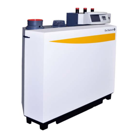
De Dietrich C230 ECO-A Series
Gas-Fired Condensing Hot Water Boiler
Models
C230 ECO-A 80
C230 ECO-A 120
C230 ECO-A 160
C230 ECO-A 200
Warning: Before you operate this boiler, read this manual carefully and take extra precautions to all safety
and warning symbols or important items. The installation and service manual is part of the documentation
along with the boiler. The installer is required to explain your heating system and boiler operating
instructions.
Notice: Please read this manual and retain for future reference. Improper installation, adjustment, alteration,
service or maintenance can cause injury, loss of life or property damage. Refer to this manual for assistance
or additional information or consult a qualified installer, service agency or the gas supplier.
Installation,
Operating and
service manual
I
mportant
This is a category II or IV boiler,
only use an approved type 'BH'
vent or equivalent, consult the
venting section in this manual.
ENG
10/2012
Advertisement
Table of Contents

Related Manuals for DeDietrich C230 ECO-A 120


Summary of Contents for DeDietrich C230 ECO-A 120
- Page 1 10/2012 De Dietrich C230 ECO-A Series Gas-Fired Condensing Hot Water Boiler Models C230 ECO-A 80 C230 ECO-A 120 C230 ECO-A 160 C230 ECO-A 200 Installation, Operating and service manual mportant This is a category II or IV boiler, only use an approved type ‘BH’...
-
Page 3: Table Of Contents
Table of contents C230 ECO-A Table of contents Preface Introduction Pictograms used Important instructions Safety Boiler description General description Boiler layout Operating principle Boiler Control 3.4.1 Temperature control 3.4.2 Low water level protection 3.4.3 Maximum protection 3.4.4 Frost protection Installation Standards and certifications Regulations governing installation Scope of delivery and installation... - Page 4 Wiring diagrams Electrical specifications 8.3.1 Mains voltage 8.3.2 Control box 8.3.3 Fuse ratings Electrical connection options 8.4.1 Connection options of standard control unit (PCU-01) 8.4.2 On/off control (OT) 8.4.3 Modulating controls (OT) 8.4.4 External interlock (BL) 8.4.5 Input release (RL) 8.4.6 Circulation pump (Pump) Connection options for the optional 0 - 10 V control PCB (IF-01)
- Page 5 Table of contents C230 ECO-A Control stops and faults 11.1 General 11.2 Control stops and faults 11.3 Control stop codes 11.4 Fault codes 11.5 Control stop - and fault memory 11.5.1 Reading faults 11.5.2 Deleting control stops or faults Service parts 12.1 General 12.2 Exploded views Technical specifications...
-
Page 7: Preface
Failure to do so may invalidate warranty or prevent the boiler from operating. The following boiler models are available: C230 ECO-A 80 (3 sections; 297 MBH (87 kW)) C230 ECO-A 120 (4 sections; 359 MBH (105 kW)) ... -
Page 8: Introduction
1 Introduction C230 ECO-A 1 Introduction Pictograms used The following pictograms are used in this document to emphasize certain instructions. This is in order to increase your personal safety and to safeguard the technical reliability of the boiler. The pictograms used are: Useful advice. -
Page 9: Safety
C230 ECO-A 2 Safety 2 Safety Adhere strictly to the specific safety instructions. Can you smell gas? Proceed as follows: Do not smoke and avoid fire and sparks. Do not operate electrical switches. Close the gas cock. ... -
Page 10: Boiler Description
3 Boiler description C230 ECO-A 3 Boiler description General description The De Dietrich C230 ECO-A is a pre-assembled, free standing, gas fired, high efficiency condensing boiler. The sectional cast aluminium heat exchanger and other major components are contained within a sealed air box. -
Page 11: Boiler Layout
C230 ECO-A 3 Boiler description Boiler layout Fig. 1 Cross-section 1. Flue gas discharge 11. Return temperature sensor 21. Flue gas switch 2. O measuring point 12. Condensate collector 22. Flow temperature sensor 3. Air box 13. Condensate trap 23. On/off 4. -
Page 12: Operating Principle
3 Boiler description C230 ECO-A Operating principle Combustion air is drawn into the closed air box through the air inlet from the plant room (open flued) or from outside via the eccentric flue system (room sealed) by the boiler gas/air supply fan. Depending on demand (under the dictates of flow/return sensor and other external/internal control inputs), the Comfort Master system determines the boiler output, which directly controls the volume of... -
Page 13: Maximum Protection
C230 ECO-A 3 Boiler description 3.4.3 Maximum protection The maximum protection switches the unit off if the water temperature is too high (230°F (110°C)) and interlocks it on the control box. Once the fault has been remedied, the unit can be reset using the reset- key. -
Page 14: Installation
4 Installation C230 ECO-A 4 Installation Standards and certifications Installation, commissioning, maintenance and repair work must only be carried out by a suitably qualified specialist. Installations must conform to national and local codes having jurisdiction. Canadian installation must conform to CSA B149 & US installation ANSI Z223.1. -
Page 15: Scope Of Delivery And Installation
C230 ECO-A 4 Installation Scope of delivery and installation The boiler is supplied fully assembled and protected. The boiler is placed on a pallet ( 28" (70 cm) x 51" (130 cm) x 57" (145 cm)), which can be transported with a pallet truck, hand truck, forklift truck or 4- wheel transport boards. - Page 16 4 Installation C230 ECO-A Dimensions Fig. 2 Elevation drawings Connection C230 ECO-A 80/120/160/200 2” NPT thread (do not remove the adapter, pipe is non-NPT) Flow 2” NPT thread (do not remove the adapter, pipe is non-NPT) Return 2” NPT thread (do not remove the adapter, pipe is non-NPT) Gas connection...
-
Page 17: Installation And Service Clearances
C230 Eco-A 4 Installation Installation and service clearances Clearance of at least 24" (600 mm) is required at the front of the boiler. However, we recommend a clearance of 40" (1 m). We recommend a clearance of at least 16" (400 mm) above the boiler control panel, at least 2"... - Page 18 4 Installation C230 ECO-A Fig. 3 Boiler room installation options (in inches and mm)
-
Page 19: Water-Side Connections
C230 ECO-A 5 Water-side connections 5 W ater-side connections 5.1.1 Flue gas condensation discharge Discharge the condensate water directly into a city water drain. In view of the acidity level of the condensate (pH between 3 and 5), use only materials that can resist flue gas condensation for the discharge pipe. -
Page 20: Circulation Pump
5 Water-side connections C230 ECO-A Please ensure that the new boiler plant is not in circuit when the flushing takes place, especially if cleansing chemicals are used to assist the process. It is important to check the inhibitor concentration after installation, system modifications, filling the system and every service in accordance with these instructions. -
Page 21: Safety Relief Valve
C230 ECO-A 5 Water-side connections 5.1.6 Safety relief valve A safety relief valve NB certified with V or HV & CRN symbols, must be installed within 20 inches on the boiler supply piping without any obstructions. The relief valve must not be smaller than 3/4 inch and not larger than 4 inch. - Page 22 5 Water-side connections C230 ECO-A It is strongly recommended that a decoupling device is installed to isolate the boiler during non working times and/or when the system or boiler flow is unknown When the boiler is connected to a refrigeration system, it must be installed so the chilled medium is piped in parallel with the boiler with appropriate valves to prevent the chilled medium from entering the boiler.
-
Page 23: Gas-Side Connections
C230 ECO-A 6 Gas-side connections 6 Gas-side connections Gas connection The boiler is suitable for use with natural gas and propane*. For other types of natural gas, consult our Technical department. All gas appliances must, by law, be installed by competent persons. Failure to install appliances correctly could lead to prosecution. -
Page 24: Gas/Air Ratio Control
6 Gas-side connections C230 ECO-A Gas system pressure checks The boiler main gas cock shutoff valve and piping must be isolated from any gas piping pressure testing in excess of 0.5 psi (35 mbar). The boiler main gas cock shutoff valve and piping must be isolated by closing the main gas cock shutoff valve during gas piping pressure testing less than 0.5 psi (35 mbar). -
Page 25: Flue Gas Discharge And Air Supply
C230 ECO-A 7 Flue gas discharge and air supply Flue gas discharge and air supply General The C230 ECO-A is suitable for both conventional room-supplied or sealed combustion. Sealed combustion terminals should comply with the local and national codes. Any horizontal pipe-work in the flue gas discharge system should slope towards the boiler. -
Page 26: Venting Options
7 Flue gas discharge and air supply C230 ECO-A Sidewall Vented & Direct Vent [Sealed Combustion] Applications A horizontal vent system with the air supply, required for combustion, provided within the boiler room or combustion air sources provided into the room. 7.1.2 Venting options The standard delivery of the C230 ECO-A boiler can be installed with... -
Page 27: Conventional Chimney Venting & Clv System Application Requirements
C230 ECO-A 7 Flue gas discharge and air supply Air supply structure The air supply pipe must also be airtight. Horizontal sections in the air supply must slope away from the boiler towards the supply opening and incorporate a drain connection if the route rises from a lower point. - Page 28 7 Flue gas discharge and air supply C230 ECO-A Fig. 7 Conventional chimney vented single boiler with room supplied combustion air...
- Page 29 C230 ECO-A 7 Flue gas discharge and air supply Fig. 8 Conventional chimney vented single boiler with sealed combustion air...
- Page 30 Model Vent diameter (min) Vent length (min) Vent length (max) inch [mm] ft [m] ft [m] 4 [100] 60 [18] C230 ECO-A 80 5 [125] 5 [1.5] 165 [50] 6 [150] 245[75] 4 [100] 25 [8] 5 [125] 165 [50] C230 ECO-A 120 5 [1.5]...
-
Page 31: Direct Vent-Sealed Combustion Application
C230 ECO-A 7 Flue gas discharge and air supply Chimney applications This venting system uses a single vent to discharge all flue gases to the outside vertically, combustion air provided with the boiler room, the air source must be sized in accordance to national codes CSA B149 &... - Page 32 7 Flue gas discharge and air supply C230 ECO -A Do not co-vent the C230 ECO -A boiler when venting the boiler either direct vent [sidewall] or in sealed combustion venting application. Venting lengths must not exceed the minimum and maximum equivalent lengths shown in Table 3.
- Page 33 C230 ECO-A 7 Flue gas discharge and air supply *Vent length tables application note: All lengths shown in chart are for both flue gas and combustion air intake vent, based on equivalent lengths: 45° Elbow = 4 ft. [1.2m] of equivalent length 90°...
-
Page 34: Co-Venting - Retrofitting
7 Flue gas discharge and air supply C230 ECO-A 7.1.7 Co-venting – Retrofitting At the time of removal of any existing boiler from a common vent system, the following steps shall be performed with each remaining appliance connected to the common vent in operation and not in operation. - Page 35 C230 ECO-A 7 Flue gas discharge and air supply Vent terminals should avoid being installed where the building exterior could be tarnished from the flue gases, a shield or another location should be considered. The vent terminals shall be installed according to the instructions as provided.
-
Page 36: Control And Electrical Connections
8 Control and electrical connections C230 ECO-A Control and electrical connections General The boiler is equipped with electronic control and safety equipment with ionization flame protection. The advanced boiler control Comfort Master, is a microprocessor that protects and controls the boiler. The boiler is fully prewired; all external connections are made on the terminal strips (24V and 120V). -
Page 37: Modulating Controls General
C230 ECO-A 8 Control and electrical connections 8.1.2 Modulating controls general The modulating nature of the boiler is used to maximum effect with a modulating controller. If the controller demands heat, the boiler supplies the heat output. If the controller demands a flow temperature, the boiler modulates to this value. -
Page 38: Wiring Diagrams
8 Control and electrical connections C230 ECO-A Wiring diagrams... - Page 39 C230 ECO-A 8 Control and electrical connections WIRE COLORS COMPONENTS BLACK Flow sensor BLUE On/off switch BROWN Blocking input GREEN FGps Flue gas pressure switch GRAY Flow temperature ORANGE Gas pressure switch Heat exchange sensor WHITE Release input YELLOW OTm / OT Open Therm YW/GN YELLOW/GREEN...
-
Page 40: Electrical Specifications
8.3.2 Control box Mains voltage : 115 V/60 Hz Power consumption at: stand-by/low load/full load: C230 ECO-A 80 : 4 / 36 / 125 W C230 ECO-A 120 : 4 / 37 / 193 W C230 ECO-A 160 : 4 / 53 / 206 W ... -
Page 41: Electrical Connection Options
C230 ECO-A 8 Control and electrical connections Electrical connection options The boiler has several control, protection and regulation connection options. The standard control PCB (PCU-01) can for example be expanded with: an optional 0 - 10 V control PCB (available as an accessory IF- 01);... -
Page 42: Input Release (Rl)
8 Control and electrical connections C230 ECO-A 8.4.5 Input release (RL) The boiler is also equipped with an input release so that the burner can be released/shutdown. This input can be used in combination with the limit switches on flue gas throttle valves, hydraulic control valves, safety interlocks, etc. -
Page 43: Analogue Input (0 - 10 V)
C230 Eco-A 8 Control and electrical connections 8.5.3 Analogue input (0 - 10 V) This control can be based on temperature or heat output (optional). The two controls are described briefly below. Connect the 0 - 10 V signal to the interface input for analogue control. -
Page 44: Analogue Input (0 - 10 V)
8 Control and electrical connections C230 ECO-A 8.5.4 Analogue input (0 - 10 V) If this feedback message is received, temperature or heat output can be selected. The two are described briefly below. Jumper (1) on the interface is used to select either temperature ( ) or boiler output (%). -
Page 45: Connection Options For The Optional 0 - 20 Ma Control Pcb
C230 ECO-A 8 Control and electrical connections Connection options for the optional 0 - 20 mA control PCB 8.6.1 Connection status (Nc) If the boiler locks out, a relay is de-energized and the alarm can be transmitted via a potential-free contact (maximum 120 V, 1 A) on terminals Nc and C of terminal strip X4. -
Page 46: Analogue Input (0 - 20 Ma)
8 Control and electrical connections C230 ECO-A modulated, where the output varies between the minimum and maximum values on the basis of the value defined by the controller. Jumper Input signal Boiler output Description [mA] 0 - 3.6* 0 – 20 Boiler off 4 - 4.4* 20 –... -
Page 47: Connection Options Of The Optional Expanded Control/Protection Pcb (Scu-S01)
C230 ECO-A 8 Control and electrical connections Connection options of the optional expanded control/protection PCB (SCU- S01) 8.7.1 Flue gas damper control (FgV) In a cascade configuration, a flue gas damper prevents flue gases from being discharged through a non-operating boiler, with flue gas cascade. -
Page 48: Outside Temperature Sensor (Tout)
8 Control and electrical connections C230 ECO-A 8.7.6 Outside temperature sensor (Tout) To take advantage of the boiler's modulating operation during the entire heating season, an outside temperature sensor (available as an accessory) can be used in combination with an on/off control or connection. -
Page 49: Commissioning
C230 ECO-A 9 Commissioning 9 Commissioning Control panel The boiler's control panel contains four function keys, a menu key, a service engineers key, an on/off switch and a display. Fig. 20 Control panel 1 = Display 5 = [Central heating temperature] or [-] key 2 = [Menu] key 6 = [+] key 3 = [Service engineers] key... -
Page 50: Fault During Start-Up Procedure
9 Commissioning C230 ECO-A : With a heat demand 1 Boiler starts 2 Burner starts 3 Central heating operation; briefly in part load then in full load When a heat demand ceases: 5 Burner stops 6 Boiler stops 0 Stand-by mode Table 12 Normal operation 9.1.2 Fault during start-up procedure... -
Page 51: Reading Current Values
C230 ECO-A 9 Commissioning 9.1.3 Reading current values The following current values can be read in the ‘information menu’ 5t = Status 5v = Sub status t1 = flow temperature [°F]; t2 = return temperature [°F]; ... -
Page 52: Adjusting The Boiler To The System
9 Commissioning C230 ECO-A Status and sub status In the ‘information menu’ the following status and sub status numbers are displayed: Sub status 5v Status 5t Number Status Number Sub status Stand-by mode Stand-by mode Anti-hunting Open hydraulic valve Boiler starts (heat demand) Start pump Wait for the correct temperatures for burner start... -
Page 53: Changing Parameters At User Level (Without Access Code)
C230 ECO-A 9 Commissioning 9.1.5 Changing parameters at user level (without access code) The following settings can be changed at user level: p1 = Flow temperature set point [°F], adjustable between 68 and 194°F (20 and 90°C); p2 = Pump post-circulation time 0..98 mins, 99 is continuous;... - Page 54 9 Commissioning C230 ECO-A Factory setting Codes in Setting range and possible Description 230- 230- 230- 230- display explanation Flow temperature set point 20 – 90°C) 176 (80°C) 68 and 194°F 0 – 98 minutes Pump post-circulation time 99 = continuous 0 = Central heating Boiler control 1 = Central heating...
- Page 55 C230 ECO-A 9 Commissioning * Change this parameter when converting to flue gas cascade and LPG gas (please refer to De Dietrich America's). The parameters at service level may only be changed by a qualified installer. Changing the factory settings can result in incorrect operation of the C230 ECO-A.
-
Page 56: Resetting Factory Settings
9 Commissioning C230 ECO-A 9.1.7 Resetting factory settings Press the -key several times until the symbol flashes in the menu bar; Select the installers menu using the -key, c;de appears in the display; Use the [-]-key or [+]-key to set installers code 0012; ... -
Page 57: Setting Manual Operation ( Symbol)
C230 ECO-A 9 Commissioning 9.1.8 Setting manual operation ( symbol) In some cases, it may be necessary to set the boiler to manual operation, for example when the controller has not yet been connected. The boiler can be set to automatic or manual operation under the symbol. - Page 58 9 Commissioning C230 ECO-A When a heat demand ceases: 5 Burner stops 6 Boiler stops 0 Stand-by mode 14. Check and, if necessary, correct the gas/air ratio control setting Perform the check at full load and minimum load for all boiler models. Only perform settings for the 230-80 and 230-120 models at minimum load.
- Page 59 C230 ECO-A 9 Commissioning Checking and setting values O for propane (G31) at full load Control Setting Control Setting Fan speed (rpm) margin margin margin margin Boiler type Full load 230-80 5600 10.0 ± 0.7 ± 1.3 < 100 230-120 5600 10.0 ±...
-
Page 60: Taking The Boiler Out Of Operation
9 Commissioning C230 ECO-A If the CO % with the 230-80 and 230-120 still deviates on full load: adjust part load (see point 15.c and 15.d) check full load (see point 15.b) ; if the CO % deviation is still too large;... - Page 61 C230 ECO-A 9 Commissioning Drain the boiler and central heating system if you are not going to use your home or the building for a long time and there is a chance of frost.
-
Page 62: Inspection And Maintenance
10 Inspection and maintenance C230 ECO-A 10 Inspection and maintenance 10.1 General The boiler must be inspected once a year and serviced/cleaned when necessary. The annual inspection of the boiler includes: combustion check of the boiler (the fan draws in the combustion air through the venturi. -
Page 63: Corrective Maintenance
C230 ECO-A 10 Inspection and maintenance 10.2.1 Corrective maintenance This should include cleaning the fan, venturi, the heat exchanger and the burner. These parts must be cleaned in succession. A service kit which contains gaskets and most used parts for maintenance is available as an accessory. - Page 64 10 Inspection and maintenance C230 ECO-A For the 230-160 and 230-200 versions: Remove the electrical connections from the fan. Remove the electrical connections from the fan. Remove the bolts that fix the venturi on the fan. Remove the bolts and the nuts from the outlet side of the fan. Remove the fan (pay attention to the sealing).
-
Page 65: Cleaning The Heat Exchanger (Flue Gas Side)
C230 ECO-A 10 Inspection and maintenance 10.2.3 Cleaning the heat exchanger (flue gas side) Caution: The sealing between the inspection hatch and heat exchanger may stick, as may the sealing between the burner and heat exchanger. Prevent the sealing from tearing. Damaged or hardened sealing must always be replaced. -
Page 66: Cleaning The Burner
10 Inspection and maintenance C230 ECO-A 10.2.4 Cleaning the burner 1. Dismantle the burner. 2. Check burner visually and if necessary clean carefully with air (e.g. compressed air at between 30 and 70 psi (2 and 5 bar), nozzle - burner distance approx. -
Page 67: Checking For Leaks
C230 ECO-A 10 Inspection and maintenance 10.5 Checking for leaks Check for water, flue gas and gas leaks. 10.6 Checking water pressure The water pressure must be a minimum of 320” w.c. (0.8 bar). The water pressure also depends on the height of the central heating system above the boiler (static pressure, 400"... -
Page 68: Control Stops And Faults
11 Control stops and faults C230 ECO-A 11 Control stops and faults 11.1 General The boiler is fitted with an advanced control unit. The heart of the control is a microprocessor, the Comfort Master, which both protects and controls the boiler. 11.2 Control stops and faults Control stop The control stop is a (temporary) boiler operating mode due to an... - Page 69 C230 ECO-A 11 Control stops and faults Code Description Possible cause Check/solution Parameter fault Reset dF and dU Check: Maximum flow No flow or insufficient Flow and/or reason for heat temperature exceeded flow demand Check: Flow (direction, pump, valves) ...
- Page 70 11 Control stops and faults C230 ECO-A Code Des cription Possible cause Check/solution existent SCU PCB not present (any longer) in boiler Check: Water pressure non- existent or too low Water pressure in the system Water pressure too low ...
-
Page 71: Fault Codes
C230 ECO-A 11 Control stops and faults Code Des cription Possible cause Check/solution Replace the VPS switch if necessary Replace the gas valve if necessary Replace the gas valve if Internal gas valve fault necessary Internal fault SU-01 ... - Page 72 11 Control stops and faults C230 ECO-A Fault Description Possible cause Check/solution code Check the cable bundle Heat exchanger Replace the sensor if necessary E:04 temperature exceeded Check: below normal range Bad connection flow (direction, pump, valves) ...
- Page 73 C230 ECO-A 11 Control stops and faults Fault Description Possible cause Check/solution code Cascade valve does not open Trap is blocked Heat exchanger is dirty Check the air supply Check: connection between ignition cable and transformer ...
-
Page 74: Control Stop - And Fault Memory
11 Control stops and faults C230 ECO-A Fault Description Possible cause Check/solution code Check the cable bundle Bad connection E:17 Gas valve control fault Replace the gas valve if Defective gas valve necessary Check the cable bundle ... -
Page 75: Reading Faults
C230 ECO-A 11 Control stops and faults n = number of times that the fault has occurred in succession hr = burner operating hours since time of fault 5t = status 5v = sub status t1 = flow temperature [°F] ... -
Page 76: Deleting Control Stops Or Faults
11 Control stops and faults C230 ECO-A 11.5.2 Deleting control stops or faults The last message in the list in the display is er:cl (or bl:cl with shutdowns) -key; the display will show: 0 Press the Press the [+]-key to set the parameter to 1. ... -
Page 77: Service Parts
C230 ECO-A 12 Service parts 12 Service parts 12.1 General If it is ascertained during the annual inspection or maintenance work that a part in the boiler must be replaced, use only original parts or parts and materials recommended by De Dietrich America's. Send the part to be replaced to De Dietrich America's. -
Page 78: Exploded Views
12 Service parts C230 ECO-A 12.2 Exploded views... - Page 79 C230 ECO-A 12 Service parts Fig. 37 Exploded views...
- Page 80 12 Service parts C230 ECO-A Part # Description Item # Boiler casing S100607 Front panel 1001 S100610 Rear panel 1002 S100599 Air supply basket 1003 S100534 Screw M6x50 (5 pc's) 1004 S100553 Sealing ring Ø 150 1006 S100291 Gasket strip Neoprene 20x6 mm (10 m) 1007 S100539 Grommet Ø...
- Page 81 C230 ECO-A 12 Service parts Part # Description Item # S100588 Top cover for condensate receiver tank 120 kW 2033 S100589 Top cover for condensate receiver tank 160 kW 2033 S100590 Top cover for condensate receiver tank 200 kW 2033 S100587 Top cover for condensate receiver tank 80 kW 2033...
- Page 82 12 Service parts C230 ECO-A Part # Description Item # S100570 Bolt M5 x 20 (10 pc's) 3028 1035 Pressure test nipple 1/8" 3029 S15524 Bolt M8 x 16 (10 pc's) 3030 S100531 Bolt M8 x 30 (10 pc's) 3031 S100055 Nut M5 (20 pc's) 3032...
-
Page 83: Technical Specifications
C230 Eco-A 13 Technical specifications 13 Technical specifications 13.1 Technical data De Dietrich C230 Eco-A Series Boiler type Unit C230-80 C230-120 C230-160 C230-200 3 Section 4 Section 5 Section 6 Section General Firing sequence operation On/off, 2 stage or fully modulating Minimum fuel input MBH [kW] 65 [19]... -
Page 84: Efficiency Information
14 Efficiency information C230 Eco-A 14 Efficiency information 14.1 Unit usable efficiency (HR efficiency) Up to 108.4% with respect to Hi at T = 86°F (30°C). Return 14.2 Water-side efficiency a. Up to 97.6% with respect to Hi at full load at an average water temperature of 158°F (176/140°F) (70°C (80/60°C)). -
Page 85: General Information
Supplied with internal heating curve. Well laid-out instrument panel with LCD display. Menu-controlled microprocessor boiler control with operating and servicing diagnostics. Available in 4 models: C230 ECO-A 80 C230 ECO-A 120 C230 ECO-A 160 ... -
Page 86: Services
15 General information C230 ECO-A Flue gas temperature switch* (only possible in combination with SCU-S01 PCB). Only one PCB (SCU-S01) board is needed for one or all of these options. 15.3 Services The following services can be supplied by De Dietrich America's: ... -
Page 87: Application Data
C230 ECO-A 16 Application data 16 Application data 16.1 General The boiler is suitable for a wide range of applications. The boiler offers numerous flue gas, hydraulic, gas and control application options, but, at the same time, is not complicated to install. This and its moderate dimensions, low noise levels and cascade options mean the boiler can be installed almost anywhere (for general legal requirements, see Section 12.2). -
Page 88: Checklists (Records)
17 Checklists (records) C230 ECO-A 17 Checklist s (records) 17.1 Checklist for commissioning (Commissioning record) Commissioning work, see Section 9.2 Measured value or confirmation 1. Fill the central heating system with water. Check the water pressure in the central heating system. 2. -
Page 89: Checklist For Maintenance (Maintenance Record)
C230 ECO-A 17 Checklists (records) 17.3 Checklist for maintenance (maintenance record) Maintenance work Confirmation and date (see Section 10) 1. Ignition electrode checked 2. Heat exchanger (central heating) cleaned 3. Combustion checked 4. Water pressure checked 5. Air supply and flue gas discharge connections checked 6. - Page 90 The manufacturer: Remeha B.V. Postbus 32 7300 AA APELDOORN, NL Tel: +31 55 5496969 Fax: +31 55 5496496 Internet: www.nl.remeha.com E-mail: remeha@remeha.com DDR AMERICAS INC In Canada: In USA or South America: 1090 Fountain St. N. , Unit #10 1054 North DuPage Avenue Cambridge, Ontario CANADA N3E 1A3 Lombard, Illinois, USA 60148 Tel: 519.650.0420 Fax: 519.650.1709...