Sign In
Upload
Download
Table of Contents
Contents
Add to my manuals
Delete from my manuals
Share
URL of this page:
HTML Link:
Bookmark this page
Add
Manual will be automatically added to "My Manuals"
Print this page
×
Bookmark added
×
Added to my manuals
Manuals
Brands
DeDietrich Manuals
Boiler
C 330 Series
Installation, user and service manual
DeDietrich C 330 Series Installation, User And Service Manual
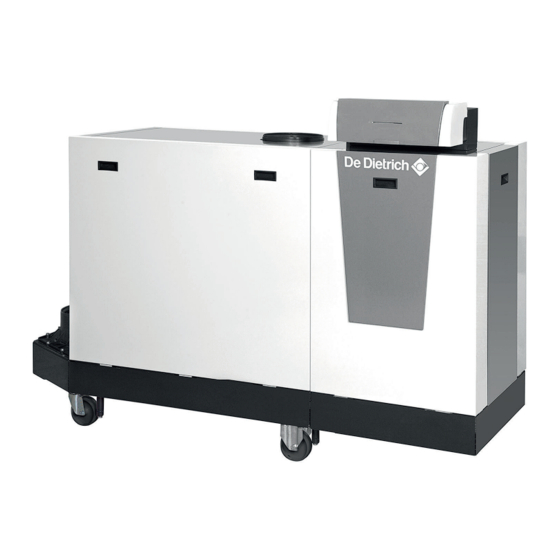
High-efficiency floor-standing boiler
Hide thumbs
1
Table Of Contents
2
3
4
5
6
7
8
9
10
11
12
13
14
15
16
17
18
19
20
21
22
23
24
25
26
27
28
29
30
31
32
33
34
35
36
37
38
39
40
41
42
43
44
45
46
47
48
49
50
51
52
53
54
55
56
57
58
59
60
61
62
63
64
65
66
67
68
69
70
71
72
73
74
75
76
77
78
79
80
81
82
83
84
85
86
87
88
89
90
91
92
page
of
92
Go
/
92
Contents
Table of Contents
Troubleshooting
Bookmarks
Table of Contents
Table of Contents
1 Safety
General Safety Instructions
Recommendations
Liabilities
Manufacturer's Liability
Installer's Liability
User's Liability
2 About this Manual
Additional Documentation
Symbols Used
Symbols Used in the Manual
3 Technical Specifications
Homologations
Certifications
Unit Categories
Directives
Factory Test
Technical Data
C 330 ECO Technical Data
C 630 ECO Technical Data
Dimensions and Connections
Boiler Type C 330 ECO
Boiler Type C 630 ECO
Electrical Diagram
4 Description of the Product
General Description
Operating Principle
Regulating the Water Temperature
Protection against Shortage of Water
Maximum Protection
Air Pressure Differential Switch
Circulating Pump
Main Components
Main Components C 330 ECO
Main Components C 630 ECO
Control Panel Description
Standard Delivery
Accessories and Options
5 Before Installation
Installation Regulations
Choice of the Location
Data Plate
Installing the Boiler C 330 ECO
Installing the Boiler C 630 ECO
Rotating the Control Panel
Transport
6 Installation
General
Hydraulic Connections
Rinsing the System
Connecting the Heating Circuit
Connecting the Condensate Discharge Pipe
Gas Connection
Air Supply/Flue Gas Connections
Material
Dimensions of Flue Gas Outlet Pipe
Length of the Air and Flue Gas Pipes
Additional Guidelines
Connecting the Flue Gas Outlet
Air Supply Connection
Electrical Connections
General
Recommendations
Control Unit
Access to the Connectors
Connection Options for the Standard PCB
Pcbs
Filling the Installation
Water Treatment
Filling the Siphon
Filling the Installation
7 Commissioning
Checklist before Commissioning
Gas Circuit
Hydraulic Circuit
Connections for the Air and Flue Gas Pipes
Electrical Connections
Commissioning Procedure
Gas Settings
Checking/Setting the Combustion
Final Instructions
8 Operation
Use of the Control Panel
Start-Up
Shutdown
Frost Protection
9 Settings
Changing the Parameters
Displaying the Measured Values
10 Maintenance
General
Standard Inspection and Maintenance Operations
Preparation
Checking the Water Pressure
Checking the Ionisation Current
Checking the Water Quality
Checking the Flue Gas Outlet/Air Supply Connections
Checking the Gas Filter
Checking the Combustion
Check the Air Supply Hose
Checking the Dirt Trap
10.2.10 Checking the Air Box
10.2.11 Checking the PS Air Pressure Differential Switch
10.2.12 Checking the VPS Gas Leakage Control
10.2.13 Checking the Gps Minimum Gas Pressure Switch
Specific Maintenance Work
General
Clean the Fan and Venturi
Cleaning and Inspecting the Non-Return Valve
Replacing the Ionisation/Ignition Electrode
Clean the Gas Filter
Cleaning the Burner
Cleaning the Burner Area
Cleaning the Heat Exchanger
Clean the Condensate Collector
10.3.10 Clean the Siphon
10.3.11 Remounting the Burner
10.3.12 Reassembling the Boiler
10.3.13 Putting the Boiler Back into Operation
11 Troubleshooting
Error Codes
12 Disposal
Removal/Recycling
13 Spare Parts
General
Parts
Parts List
14 Appendix
Erp Information
Product Fiche
EC Declaration of Conformity
Advertisement
Quick Links
1
Technical Specifications
2
C 630 Eco Technical Data
3
Error Codes
Download this manual
en
PROJECT
C 330 / C 630
Installation, User and Service Manual
High-efficiency floor-standing boiler
S U S T A I N A B L E C O M F O R T ®
Table of
Contents
Previous
Page
Next
Page
1
2
3
4
5
Advertisement
Table of Contents
Need help?
Do you have a question about the C 330 Series and is the answer not in the manual?
Ask a question
Questions and answers
Related Manuals for DeDietrich C 330 Series
Boiler DeDietrich C 630 ECO Installation, User And Service Manual
Gas fired floor-standing condensing boiler (92 pages)
Boiler DeDietrich C 330 ECO Installation, User And Service Manual
Gas fired floor-standing condensing boiler (92 pages)
Boiler DeDietrich GTU C 330 Installation And Service Manual
Oil-fired condensing boiler (52 pages)
Boiler DeDietrich GTU C 330 User Manual
Oil-fired condensing boiler (32 pages)
Boiler DeDietrich NeOvo Condens EFU C 19 User Manual
Oil-fired condensing boiler (44 pages)
Boiler DeDietrich C 310 ECO User Manual
Gas fired condensing boiler (20 pages)
Boiler DeDietrich C 340 Series Installation And User Manual
High-efficiency floor-standing gas boiler with diematic evolution scb-01, diematic evolution scb-10 (220 pages)
Boiler DeDietrich CBI-II User Manual
Reverse combustion log-fired boiler (16 pages)
Boiler DeDietrich Range GT 120 Instructions For Use Manual
Low temperature fuel oil boiler oil-fired condensation boiler (12 pages)
Boiler DeDietrich C 230 ECO User Manual
Gas fired condensing boiler (24 pages)
Boiler DeDietrich C 230 ECO Installation And Service Manual
Gas fired condensing boiler (60 pages)
Boiler DeDietrich CBB 15 E User Manual
Reverse combustion log-fired boiler (16 pages)
Boiler DeDietrich C 210 ECO Technical Instructions
Gas fired condensing boiler (68 pages)
Boiler DeDietrich CBB Series User Manual
Wood-burning boiler (20 pages)
Boiler DeDietrich ESSENCIO CF 22 User Manual
Oil/gas-fired boiler (44 pages)
Boiler DeDietrich CESL C50 Instruction Manual
(47 pages)
This manual is also suitable for:
C 630 series
C 330 eco 280
C 630 eco 560
C 630 eco 1000
C 630 eco 1140
C 630 eco 1300
...
Show all
C 330 eco
C 630 eco
Table of Contents
Print
Rename the bookmark
Delete bookmark?
Delete from my manuals?
Login
Sign In
OR
Sign in with Facebook
Sign in with Google
Upload manual
Upload from disk
Upload from URL


Need help?
Do you have a question about the C 330 Series and is the answer not in the manual?
Questions and answers