Table of Contents
Advertisement
Quick Links
Advertisement
Table of Contents

Related Manuals for Intel 480T


Summary of Contents for Intel 480T
- Page 1 Intel NetStructure ® ™ 480T Routing Switch User Guide...
- Page 2 Copyright © 2000, Intel Corporation. All rights reserved. Intel Corporation, 5200 NE Elam Young Parkway, Hillsboro OR 97124-6497 Intel Corporation assumes no responsibility for errors or omissions in this manual. Nor does Intel make any commitment to update the information contained herein.
-
Page 3: Table Of Contents
Unicast Routing ............ 19 IP Multicast Routing..........20 Load Sharing............20 Software Licensing ............. 20 Router Licensing........... 20 480T Switch Front View..........22 480T Switch Rear View..........23 AC Connector ............23 Serial Number ............23 Console Port............23 Management Port ..........24 MAC Address ............ - Page 4 T a b l e o f C o n t e n t s Logging In for the First Time ........33 Installing the Gigabit Interface Connector (GBIC) ..34 Chapter 3 Accessing the Switch Understanding the Command Syntax ......36 Syntax Helper ............
- Page 5 T a b l e o f C o n t e n t s Using Web Device Manager........68 Controlling Web Access ........68 Using SNMP ............... 69 Accessing Switch Agents........69 Supported MIBs ............ 70 Configuring SNMP Settings ......... 70 Displaying SNMP Settings ........
- Page 6 T a b l e o f C o n t e n t s Precedence of Tagged Packets Over Protocol Filters ..............97 VLAN Names ............. 97 Default VLAN ............98 Configuring VLANs on the Switch ......98 VLAN Configuration Examples ......100 Displaying VLAN Settings ........
- Page 7 T a b l e o f C o n t e n t s Displaying STP Settings ........... 125 Disabling and Resetting STP ........125 Chapter 8 Quality of Service (QoS) Overview of Policy-Based Quality of Service..127 Performance Impact ..........128 Building Blocks ............
- Page 8 T a b l e o f C o n t e n t s ESRP Examples ..........159 Displaying ESRP Information ........163 Chapter 10 IP Unicast Routing Overview of IP Unicast Routing....... 165 Router Interfaces..........166 Populating the Routing Table ......167 Proxy ARP ..............
- Page 9 T a b l e o f C o n t e n t s Chapter 11 RIP and OSPF Overview..............197 RIP Versus OSPF..........198 Overview of RIP ............199 Routing Table ............. 199 Split Horizon............200 Poison Reverse............ 200 Triggered Updates..........
- Page 10 T a b l e o f C o n t e n t s Chapter 13 IPX Routing Overview of IPX* ............. 237 Router Interfaces..........237 IPX Encapsulation Types........239 Populating the Routing Table ......239 IPX/RIP Routing............240 Routing SAP Advertisements ......
- Page 11 Do a GET When Configuring a VLAN ....292 ® Chapter 17 Using Intel Device View Installing Intel Device View ........296 To Install Intel Device View....... 296 Starting Intel Device View ........297 Windows Version ..........297 Web Version ............297...
- Page 12 T a b l e o f C o n t e n t s To Install and Configure a New Switch for Management............298 Using the Device Tree ..........299 Device Tree icons ..........300 Managing a Switch ........... 302 Viewing RMON Information........
-
Page 13: Introduction
This section includes an overview of this guide, describes guide conventions, and lists other useful publications. Introduction ® This guide provides the information you need to configure the Intel ™ NetStructure 480T Routing switch. It is intended for use by network administrators who are responsible for... -
Page 14: Conventions
P R E F A C E • Internet Packet Exchange (IPX) concepts • Simple Network Management Protocol (SNMP) Note If the information in the “Late Breaking News” shipped with your switch differs from the information in this guide, follow the “Late Breaking News.” Conventions Table 1 lists conventions that are used throughout this guide. -
Page 15: Related Publications
Command Line Interface Reference Guide ® ™ • Intel NetStructure 480T Routing Switch Quick Start Guide • “Late Breaking News” Documentation for Intel products is available on the World Wide Web at the following location: • Intel home page http://support.intel.com... - Page 16 P R E F A C E...
-
Page 17: Chapter 1 Overview
• How to use the switch in your network configuration • Software factory default settings Summary of Features The features of the 480T switch include the following: • Virtual local area networks (VLANs) including support for IEEE 802.1Q • IEEE 802.1p - priority queuing •... - Page 18 RADIUS client and per-command authentication support • Console command-line interface (CLI) connection • Telnet CLI connection • Web-based management interface • Simple Network Management Protocol (SNMP) support • Remote Monitoring (RMON) • Traffic mirroring for all ports ® • Intel Device View (IDV) support...
-
Page 19: Media Types And Distances
C H A P T E R 1 Overview Media Types and Distances Table 2 describes the media types and distances for the different types of 480T switch ports. Table 2: Media Types and Distances Mhz/ Maximum Standard Media Type... -
Page 20: Full-Duplex Support
OR BY ADDING OF FIXED OPTICAL ATTENUATOR AT THE RECEIVER END Full-Duplex Support The 480T switch provides full-duplex support for all ports. Full- duplex mode allows frames to be transmitted and received simultaneously and, in effect, doubles the bandwidth available on a link. -
Page 21: Quality Of Service (Qos)
C H A P T E R 1 Overview • They ease the change and movement of devices on networks. For more information, refer to Chapter 5,Virtual LANs. Spanning Tree Protocol The switch supports the IEEE 802.1D Spanning Tree Protocol (STP), which is a bridge-based mechanism for providing fault tolerance on networks and/or voice traffic loops due to mis-cabling. -
Page 22: Ip Multicast Routing
IP Multicast Routing The switch can use IP multicasting to allow a single IP host to transmit a packet to a group of IP hosts. The 480T switch supports multicast routes that are learned by way of the Distance Vector Multicast Routing Protocol (DVMRP) or Protocol Independent Multicast-Dense Mode (PIM-DM). -
Page 23: Basic Functionality
Intel. The voucher contains instructions on obtaining a license key from the Intel web site at support.intel.com. Once a license key is entered, it is not necessary to enter the information again. However, we recommend keeping the... -
Page 24: T Switch Front View
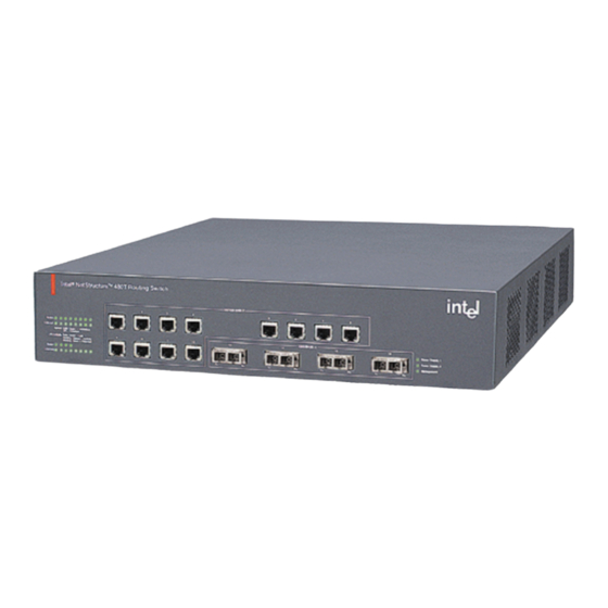
Port status LEDs Gigabit Ethernet ports 480t_fr Figure 1: 480T switch front view The 480T switch has 100/1000Mbps ports, and four gigabit-only ports. Ports 13 through 16 use modular GBIC connectors. Note For information on supported media types and distances, refer to Table 2. -
Page 25: T Switch Rear View
C H A P T E R 1 Overview 480T Switch Rear View Figure 2 shows the two 480T switch rear view configurations. AC Connector Reset Console port N232 100-120/200-240 MADE IN USA with partial foreign content 130116-00 Rev01 Management port... -
Page 26: Management Port
C H A P T E R 1 Overview Management Port The management port (RJ-45 connector) is a 10/100 Mbps Ethernet connection used for out-of-band management. MAC Address This label shows the unique Ethernet MAC address assigned to this device. Switch LEDs Table 4 describes the light emitting diode (LED) behavior on the switch. - Page 27 C H A P T E R 1 Overview Table 4: Switch LEDs (continued) Color Indicates 10/100 Management Port Status LEDs Link/activity Green Link is present. Orange Frames are being transmitted/received on this port. Link is not present. Power Status LEDs Power 1 and Green Either or both LEDs green indicates the Switch is...
-
Page 28: Software Factory Defaults
C H A P T E R 1 Overview Software Factory Defaults Table 5 lists factory defaults for global features. Table 5: Global Factory Defaults Item Default Setting Serial or Telnet user admin with no password and user with account no password Web network Enabled... - Page 29 C H A P T E R 1 Overview Table 5: Global Factory Defaults (continued) Item Default Setting Virtual LANs Three VLANs pre-defined. VLAN named default contains all ports and belongs to the STPD named s0. VLAN mgmt contains only the 10/100 Ethernet management port, and exists only on switches that have an Ethernet management port.
- Page 30 C H A P T E R 1 Overview Table 5: Global Factory Defaults (continued) Item Default Setting IPX routing Disabled Disabled Disabled Port mirroring Disabled Note For default settings of individual features, refer to individual chapters in this guide.
-
Page 31: Chapter 2 Installation And Setup
Installation and Setup This chapter describes the following: ® ™ • How to decide where to install the Intel NetStructure 480T Routing Switch • Gigabit Ethernet configuration rules • How to install the switch in a rack or free-standing •... -
Page 32: Installing The Switch
C H A P T E R 2 Installation and Setup When deciding where to install the switch, ensure that: • The switch is accessible and cables can be connected easily. • Water or moisture cannot enter the case of the unit. •... -
Page 33: Free-Standing
C H A P T E R 2 Installation and Setup 480t_028 Figure 3: Fitting the mounting bracket Repeat the three previous steps for the other side of the switch. Insert the switch into the 19-inch rack. Ensure that ventilation holes are not obstructed. -
Page 34: Connecting Equipment To The Console Port
Powering On the Switch To turn on power to the switch, connect the AC power cable to the switch and then to the wall outlet. The 480T switch has no on/off switch. Checking the Installation After plugging in the switch, the device performs a Power On Self- Test (POST). -
Page 35: Logging In For The First Time
C H A P T E R 2 Installation and Setup Logging In for the First Time After the switch has completed the POST, it is operational. Once operational, you can log in to the switch and configure an IP address for the default VLAN (named default). -
Page 36: Installing The Gigabit Interface Connector (Gbic)
Connector (GBIC) GBICs can be added and removed from the switch without powering off the system. There are three types of GBIC modules available for the 480T switch: 1000BASE-SX, 1000BASE-LX, and 1000LH. Figure 4 illustrates a typical GBIC. 480t_027 Figure 4: GBIC module GBICs are a Class 1 laser device. -
Page 37: Chapter 3 Accessing The Switch
Accessing the Switch This chapter provides the following information to help you manage the ® ™ Intel NetStructure 480T Routing Switch: • Understanding the command syntax • Line-editing commands • Command history substitution • Configuring the switch for management •... -
Page 38: Understanding The Command Syntax
C H A P T E R 3 Accessing the Switch Understanding the Command Syntax This section describes the steps to take when entering a command. Refer to the sections that follow for detailed information on using the command-line interface. To use the command-line interface (CLI), follow these steps: When entering a command at the prompt, ensure that you have the appropriate privilege level. -
Page 39: Command Completion With Syntax Helper
C H A P T E R 3 Accessing the Switch Command Completion with Syntax Helper The local management software provides command completion by way of the [Tab] key. If you enter a partial command, pressing the [Tab] key posts a list of available options, and places the cursor at the end of the command. -
Page 40: Names
C H A P T E R 3 Accessing the Switch You can add additional port numbers to the list, separated by a comma: port 1-3,6,8 Names All named components of the switch configuration must have a unique name. Names must begin with an alphabetical character and are delimited by whitespace, unless enclosed in quotation marks. -
Page 41: Line-Editing Keys
C H A P T E R 3 Accessing the Switch Table 6: Command Syntax Symbols (continued) Symbol Description Braces enclose an optional value or a list of optional arguments. One or more values or arguments can be specified. For example, in the syntax reboot {<date>... -
Page 42: Command History
C H A P T E R 3 Accessing the Switch Table 7: Line-Editing Keys (continued) Key(s) Description [Ctrl] + N or Displays the next command in the command history buffer and places Down Arrow cursor at end of command. [Ctrl] + U Clears all characters typed from the cursor to the beginning of the line. - Page 43 C H A P T E R 3 Accessing the Switch Table 8: Common Commands (continued) Command Description config banner Configures the banner string. You can enter up to 24 rows of 79-column text that is displayed before the login prompt of each session.
- Page 44 C H A P T E R 3 Accessing the Switch Table 8: Common Commands (continued) Command Description create vlan <name> Creates a VLAN. delete account <username> Deletes a user account. delete vlan <name> Deletes a VLAN. disable bootp vlan [<name> | all] Disables BOOTP for one or more VLANs.
- Page 45 C H A P T E R 3 Accessing the Switch Table 8: Common Commands (continued) Command Description enable idletimeout Enables a timer that disconnects all sessions (both Telnet and console) after 20 minutes of inactivity. The default setting is disabled. enable license full_L3 <license_key>...
-
Page 46: Configuring Management Access
C H A P T E R 3 Accessing the Switch Table 8: Common Commands (continued) Command Description unconfig switch {all} Resets all switch parameters (with the exception of defined user accounts, and date and time information) to the factory defaults. - Page 47 C H A P T E R 3 Accessing the Switch A user-level account has viewing access to all manageable parameters, with the exception of the following: • User account database • SNMP community strings A user-level account can use the command to test device ping reachability, and change the password assigned to the account...
-
Page 48: Default Accounts
C H A P T E R 3 Accessing the Switch Default Accounts By default, the switch is configured with two accounts, as shown in Table 9. Table 9: Default Accounts Account Name Access Level admin This user can access and change all manageable parameters. -
Page 49: Creating A Management Account
C H A P T E R 3 Accessing the Switch To add a password to the default user account: Log in to the switch using the name admin. At the password prompt, press [Return], or enter the password that you have configured for the admin account. Add a default user password by typing the following: config account user Enter the new password at the prompt. -
Page 50: Methods Of Managing The Switch
C H A P T E R 3 Accessing the Switch Deleting an Account To delete a account, you must have administrator privileges. Use the following command to delete an account: delete account <username> Note The account name admin cannot be deleted. Methods of Managing the Switch You can manage the switch using the following methods: •... -
Page 51: Using Access Profiles
C H A P T E R 3 Accessing the Switch Using Access Profiles Access profiles are used by several switch features as a way to restrict access. An access profile is typically a named list of IP addresses and masks. To use access profiles, first define the list, and then apply the named list to the desired application. - Page 52 C H A P T E R 3 Accessing the Switch Table 10: Access Profile Configuration Commands (continued) Command Description config access-profile <access_profile> Configures the access profile to be one of the mode [permit | deny] following: — Allows the addresses that match the permit access profile description.
-
Page 53: Access Profile Rules
C H A P T E R 3 Accessing the Switch Access Profile Rules The following rules apply when using access profiles: • Only one access profile can be applied to each application. • The access profile can either permit or deny the entries in the profile. -
Page 54: Connecting To Another Host Using Telnet
C H A P T E R 3 Accessing the Switch Before you can start a Telnet session, you must set up the IP parameters described in the section “Configuring Switch IP Parameters,” later in this chapter. Telnet is enabled by default. To open the Telnet session, you must specify the IP address of the device that you want to manage. - Page 55 C H A P T E R 3 Accessing the Switch You can enable BOOTP on a per-VLAN basis by using the following command: enable bootp vlan [<name> | all] By default, BOOTP is enabled on the default VLAN. If you configure the switch to use BOOTP, the switch IP address is not retained through a power cycle, even if the configuration has been saved.
- Page 56 C H A P T E R 3 Accessing the Switch If you are logging in for the first time, use the default user name admin to log in with administrator privileges. For example: login: admin Administrator capabilities enable you to access all switch functions.
-
Page 57: Disconnecting A Telnet Session
C H A P T E R 3 Accessing the Switch When you have finished using the facility, log out of the switch by typing logout quit Disconnecting a Telnet Session An administrator-level account can disconnect a management session that has been established by way of a Telnet connection. If this happens, the user logged in by way of the Telnet connection is notified that the session has been terminated. -
Page 58: Radius * Client
C H A P T E R 3 Accessing the Switch To re-enable Telnet on the switch, at the console port use the following command: enable telnet RADIUS Client Remote Authentication Dial In User Service (RADIUS, RFC 2138) is a mechanism for authenticating and centrally administrating access to network nodes. - Page 59 C H A P T E R 3 Accessing the Switch value is 1645. The client IP address is the IP address used by the RADIUS server for communicating back to the switch. RADIUS commands are described in Table 11. Table 11: RADIUS Commands Command Description...
- Page 60 C H A P T E R 3 Accessing the Switch Table 11: RADIUS Commands (continued) Command Description config radius-accounting [primary | secondary] Configures the RADIUS accounting server [<ipaddress> | <hostname>] {<udp_port>} server. Specify the following: client-ip <ipaddress> • [primary | secondary] — Configure either the primary or secondary RADIUS server.
-
Page 61: Radius Rfc 2138 Attributes
C H A P T E R 3 Accessing the Switch Table 11: RADIUS Commands (continued) Command Description enable radius-accounting Enables RADIUS accounting. The RADIUS client must also be enabled. show radius Displays the current RADIUS and RADIUS accounting client configuration and statistics. -
Page 62: Ip Host Configuration Commands
C H A P T E R 3 Accessing the Switch IP Host Configuration Commands Table 12 describes the commands that are used to configure IP settings on the switch. Table 12: IP Host Configuration Commands Command Description clear iparp {<ipaddress> | vlan <name>} Removes dynamic entries in the IP ARP table. -
Page 63: Domain Name Service Client Services
C H A P T E R 3 Accessing the Switch Table 12: IP Host Configuration Commands (continued) Command Description show ipconfig {vlan <name>} Displays configuration information for one or all VLANs. show iproute {priority | vlan <name> | permanent | Displays the contents of the IP routing <ipaddress>... -
Page 64: Using The Simple Network Time Protocol
Configures the domain that the DNS client uses if a fully qualified domain name is not entered. For example, if the default domain is configured to be executing intel.com, ping support searches for support.intel.com config dns-client delete <ipaddress> Removes a DNS server. -
Page 65: Configuring And Using Sntp
C H A P T E R 3 Accessing the Switch Configuring and Using SNTP To use SNTP: Identify the host(s) that are configured as NTP server(s). Additionally, identify the preferred method for obtaining NTP updates. The options are for the NTP server to send out broad- casts, or for switches using NTP to query the NTP server(s) directly. - Page 66 C H A P T E R 3 Accessing the Switch Table 14: Greenwich Mean Time Offsets (continued) Offset in Offset in Common Time Zone Hours Minutes References Cities -6:00 -360 CST - Central Standard Mexico City, Mexico Saskatchewan, Canada -7:00 -420 MST - Mountain Standard...
- Page 67 C H A P T E R 3 Accessing the Switch Table 14: Greenwich Mean Time Offsets (continued) Offset in Offset in Common Time Zone Hours Minutes References Cities +4:00 +240 ZP4 - Russia Zone 3 Abu Dhabi, UAE; Muscat; Tblisi;...
- Page 68 C H A P T E R 3 Accessing the Switch The command syntax to configure GMT offset and usage of Daylight Savings is as follows: config timezone <GMT_offset> {autodst | noautodst} The GMT_OFFSET is in +/- minutes from the GMT time. Automatic Daylight Savings Time (DST) changes can be enabled or disabled.
-
Page 69: Sntp Configuration Commands
C H A P T E R 3 Accessing the Switch You can verify the configuration using the following com- mands: show sntp-client This command provides configuration and statistics associated with SNTP and its connectivity to the NTP server. show switch This command indicates the GMT offset, Daylight Savings Time, and the current local time. -
Page 70: Sntp Example
10.0.1.2 Using Web Device Manager ® The Intel Web Device Manager is device-management software running in the switch that enables you to access the switch over a TCP/IP network using a standard Web browser. Any properly... -
Page 71: Using Snmp
C H A P T E R 3 Accessing the Switch To configure Web access to use an access profile, use the following command: enable web {access-profile <access-profile> | none} {port <tcp_port_number>} Use the option to remove a previously configured access none profile. -
Page 72: Supported Mibs
C H A P T E R 3 Accessing the Switch Supported MIBs In addition to private MIBs, the switch supports the standard MIBs listed in Appendix A. Configuring SNMP Settings The following SNMP parameters can be configured on the switch: •... - Page 73 System name — The system name is the name that you have assigned to this switch. The default name is the model name of the switch (for example, 480T switch). • System location (optional) — Using the system location field, you can enter a location for this switch.
-
Page 74: Displaying Snmp Settings
Configures the name of the switch. A maximum of 32 characters is allowed. The default sysname is the model name of the device (for example, ). The 480T appears in the switch prompt. sysname enable snmp traps Enables SNMP trap support. -
Page 75: Resetting And Disabling Snmp
C H A P T E R 3 Accessing the Switch This command displays the following information: • Enable/disable state for Telnet, SSH2, SNMP, and Web access, along with access profile information • SNMP community strings • Authorized SNMP station list •... -
Page 76: Ping
C H A P T E R 3 Accessing the Switch Ping command enables you to send Internet Control Message ping Protocol (ICMP) echo messages to a remote IP device. The ping command is available for both the user and administrator privilege level. -
Page 77: Chapter 4 Configuring Switch Ports
Configuring Switch Ports ® ™ This chapter describes how to configure ports on the Intel NetStructure 480T Routing Switch and covers the following topics: • Enabling and disabling ports • Configuring port speed and duplex settings • Port commands •... -
Page 78: Configuring Port Speed And Duplex Setting
C H A P T E R 4 Configuring Switch Ports Configuring Port Speed and Duplex Setting By default, the switch is configured to use autonegotiation to determine the port speed and duplex setting for each port. You can select to manually configure the duplex setting and the speed of 100/1000 Mbps ports, and you can manually configure the duplex setting on Gigabit Ethernet ports. -
Page 79: Port Commands
C H A P T E R 4 Configuring Switch Ports The following example turns autonegotiation off for port 4 (a Gigabit Ethernet port): config ports 4 auto off duplex full Port Commands Table 19 describes the port commands. Table 19: Port Commands Command Description config jumbo-frame size... - Page 80 C H A P T E R 4 Configuring Switch Ports Table 19: Port Commands (continued) Command Description disable learning ports <portlist> Disables MAC address learning on one or more ports for security purposes. If MAC address learning is disabled, only broadcast traffic, EDP traffic, and packets destined to a permanent MAC address matching that port number, are forwarded to the port.
- Page 81 C H A P T E R 4 Configuring Switch Ports Table 19: Port Commands (continued) Command Description restart ports <portlist> Resets autonegotiation for one or more ports by resetting the physical link. show ports {<portlist>} collisions Displays real-time collision statistics. show ports {<portlist>} configuration Displays the port configuration.
-
Page 82: Jumbo Frames
Jumbo frames are Ethernet frames that are larger than 1522 bytes, including four bytes used for the cyclic redundancy check (CRC). The 480T switch supports switching and routing of jumbo frames at wire-speed on all ports. Jumbo frames are used between endstations that support larger frame sizes for more efficient transfers of bulk data. -
Page 83: Load Sharing Algorithms
Load sharing must be enabled on both ends of the link, or a network loop will result. This feature is supported between 480T switches only, but may be compatible with third-party “trunking” or sharing algorithms. Load Sharing Algorithms... -
Page 84: Configuring Load Sharing
C H A P T E R 4 Configuring Switch Ports If you do not explicitly select an algorithm, the port-based scheme is used. However, the address-based algorithm has a more even distribution and is the recommended choice. Configuring Load Sharing To set up the switch to load share among ports, you must create a load-sharing group of ports. -
Page 85: Verifying The Load Sharing Configuration
C H A P T E R 4 Configuring Switch Ports indication that the port is not in a forward state, and the partner switch continues to forward packets. Verifying the Load Sharing Configuration The screen output resulting from the show ports configuration command indicates the ports are involved in load sharing and the master logical port identity. -
Page 86: Port-Mirroring Commands
C H A P T E R 4 Configuring Switch Ports Port-Mirroring Commands Port-mirroring commands are described in Table 20. Table 20: Port-Mirroring Configuration Commands Command Description config mirroring add [mac <mac_address> | Adds a single mirroring filter definition. Up to vlan <name>... -
Page 87: Enterprise Discovery Protocol
Configuring Switch Ports Enterprise Discovery Protocol The Enterprise Discovery Protocol (EDP) is used to gather information about neighbor 480T switches. EDP is used by the switches to exchange topology information. EDP is also used by the Enterprise Standby Router Protocol (ESRP). Information communicated using EDP includes the following: •... - Page 88 C H A P T E R 4 Configuring Switch Ports...
-
Page 89: Chapter 5 Virtual Lans (Vlans)
This chapter describes the concept of VLANs and explains how to ® ™ implement VLANs on the Intel NetStructure 480T Routing Switch. Overview of Virtual LANs The term “VLAN” is used to refer to a collection of devices that communicate as if they were on the same physical LAN. -
Page 90: Types Of Vlans
C H A P T E R 5 Virtual LANs (VLANs) because each VLAN can be set up to contain only those devices that must communicate with each other. • VLANs provide extra security. Devices within each VLAN can only communicate with member devices in the same VLAN. - Page 91 C H A P T E R 5 Virtual LANs (VLANs) For example, on the switch in Figure 5, ports 1 through 4 are part of VLAN Marketing; ports 9 through 12 are part of VLAN Sales; and ports 5 through 8 and 15 and 16 are in VLAN Finance. Finance Marketing Sales...
- Page 92 C H A P T E R 5 Virtual LANs (VLANs) Figure 6 illustrates a single VLAN that spans two 480T switches. All ports on both switches belong to VLAN Sales. The two switches are connected using port 13 System 1, and port 16 on System 2.
-
Page 93: Tagged Vlans
C H A P T E R 5 Virtual LANs (VLANs) Figure 7 illustrates two VLANs spanning two switches. On System 1, ports 9 through 12 are part of VLAN Accounting; ports 13 through 16 are part of VLAN Engineering. On System 2, ports 1 through 4 are part of VLAN Accounting;... - Page 94 C H A P T E R 5 Virtual LANs (VLANs) Uses of Tagged VLANs Tagging is most commonly used to create VLANs that span switches. The switch-to-switch connections are typically called trunks. Using tags, multiple VLANs can span multiple switches using one or more trunks.
- Page 95 C H A P T E R 5 Virtual LANs (VLANs) Switch 1 = Marketing = Sales 802.1Q = Tagged port Tagged server Switch 2 480t_001 Figure 8: Physical diagram of tagged and untagged traffic Figure 9 shows a logical diagram of the same network. Sales Marketing Switch 1...
-
Page 96: Protocol-Based Vlans
C H A P T E R 5 Virtual LANs (VLANs) • The server connected to port 9 on System 1 has a NIC that supports 802.1Q tagging. • The server connected to port 9 on System 1 is a member of both VLAN Marketing and VLAN Sales. - Page 97 C H A P T E R 5 Virtual LANs (VLANs) 192.207.35.1 192.207.36.1 My Company 192.207.35.0 192.207.36.0 Finance Personnel = IP traffic = All other traffic 480t_003 Figure 10: Protocol-based VLANs Predefined Protocol Filters The following protocol filters are predefined on the switch: •...
-
Page 98: Defining Protocol Filters
C H A P T E R 5 Virtual LANs (VLANs) Defining Protocol Filters If necessary, you can define a customized protocol filter based on EtherType, Logical Link Control (LLC), and/or Subnetwork Access Protocol (SNAP). Up to six protocols may be part of a protocol filter. -
Page 99: Precedence Of Tagged Packets Over Protocol Filters
C H A P T E R 5 Virtual LANs (VLANs) A maximum of fifteen protocol filters, each containing a maximum of six protocols, can be defined. All fifteen protocol filters can be active and configured for use. For more information on SNAP for Ethernet protocol types, see TR 11802-5:1997 (ISO/IEC) [ANSI/IEEE std. -
Page 100: Default Vlan
C H A P T E R 5 Virtual LANs (VLANs) VLAN names are locally significant. That is, VLAN names used on one switch are only meaningful to that switch. If another switch is connected to it, the VLAN names have no significance to the other switch. - Page 101 C H A P T E R 5 Virtual LANs (VLANs) Table 22: VLAN Configuration Commands Command Description config dot1q ethertype <ethertype> Configures an IEEE 802.1Q Ethertype. Use this command only if you have another switch that supports 802.1Q, but uses a different Ethertype value than 8100.
-
Page 102: Vlan Configuration Examples
C H A P T E R 5 Virtual LANs (VLANs) Table 22: VLAN Configuration Commands (continued) Command Description config vlan <name> qosprofile <qosname> Configures a VLAN to use a particular QoS profile. Dynamic FDB entries associated with the VLAN are flushed once the change is committed. -
Page 103: Displaying Vlan Settings
C H A P T E R 5 Virtual LANs (VLANs) The following example creates a VLAN named sales, with the VLANid 120. The VLAN uses both tagged and untagged ports. Ports 1 through 3 are tagged, and ports 4 and 7 are untagged. Note that when not explicitly specified, ports are added as untagged. -
Page 104: Deleting Vlans
C H A P T E R 5 Virtual LANs (VLANs) • Ports assigned • Tagged/untagged status for each port • How the ports were added to the VLAN (manually or by GVRP) Use the option to display the detailed format. detail To display protocol information, use the following command: show protocol {<protocol>}... -
Page 105: Generic Vlan Registration Protocol
C H A P T E R 5 Virtual LANs (VLANs) Generic VLAN Registration Protocol The Generic VLAN Registration Protocol (GVRP) allows a LAN device to signal other neighboring devices that it wishes to receive packets for one or more VLANs. The GVRP protocol is defined as part of the IEEE 802.1Q Virtual LANs draft standard. -
Page 106: Gvrp And Spanning Tree Domains
C H A P T E R 5 Virtual LANs (VLANs) The configuration for Switch A is as follows: create vlan red config vlan red tag 10 config vlan red add port 1-2 untagged enable gvrp Switch B does not need to be configured with VLAN or tagging information. -
Page 107: Mac-Based Vlans
C H A P T E R 5 Virtual LANs (VLANs) Table 24: GVRP Commands Command Description config gvrp [listen | send | both | none] port Configures the sending and receiving GVRP <portlist> information one or all a ports. Options include the following: •... -
Page 108: Mac-Based Vlan Guidelines
C H A P T E R 5 Virtual LANs (VLANs) MAC-Based VLAN Guidelines When using the MAC-to-VLAN mapping, consider the following guidelines: • A port can only accept connections from an endstation/host and should not be connected to a layer-2 repeater device. Connecting to a layer-2 repeater device can cause certain addresses to not be mapped to their respective VLAN if they are not correctly configured in the MAC-VLAN configuration database. -
Page 109: Mac-Based Vlan Limitations
C H A P T E R 5 Virtual LANs (VLANs) • Partial configurations of the MAC to VLAN database can be downloaded to the switch using the timed download configuration feature. MAC-Based VLAN Limitations The following list contains the limitations of MAC-based VLANs: •... -
Page 110: Mac-Based Vlan Example
C H A P T E R 5 Virtual LANs (VLANs) Table 25: MAC-Based VLAN Commands (continued) Command Description show mac-vlan {configuration | database} Displays the MAC-based VLAN configuration and MAC address database content. MAC-Based VLAN Example In this following example, three VLANs are created: engineering, marketing, and sales. - Page 111 C H A P T E R 5 Virtual LANs (VLANs) To configure the primary and/or secondary server and file name, use the following command: config download server [primary | secondary] <host_name> | <ip_address> <filename> To enable time interval downloads, use the following command: download configuration every <hour (0-23)>...
- Page 112 C H A P T E R 5 Virtual LANs (VLANs)
-
Page 113: Chapter 6 Forwarding Database (Fdb)
™ The Intel NetStructure 480T Routing Switch maintains a database of all media access control (MAC) addresses received on all of its ports. It uses the information in this database to decide whether a frame should be forwarded or filtered. - Page 114 MAC address. All entries entered by way of the command-line interface are stored as permanent. The 480T switch can support a maximum of 64 permanent entries. Once created, permanent entries stay the same as when they were created.
-
Page 115: How Fdb Entries Get Added
C H A P T E R 6 Forwarding Database (FDB) How FDB Entries Get Added Entries are added into the FDB in the following two ways: • The switch can learn entries. The system updates its FDB with the source MAC address from a packet, the VLAN, and the port identifier on which the source packet is received. -
Page 116: Fdb Configuration Examples
C H A P T E R 6 Forwarding Database (FDB) Table 26: FDB Configuration Commands (continued) Command Description create fdbentry <mac_address> vlan Creates an FDB entry. Specify the following: <name> [blackhole | <portlist> | • — Device MAC address, using mac_address dynamic] {qosprofile <qosprofile>} colon separated bytes. -
Page 117: Displaying Fdb Entries
C H A P T E R 6 Forwarding Database (FDB) • VLAN name is marketing. • Slot number for this device is 3. • Port number for this device is 4. This example associates the QoS profile qp2 with a dynamic entry that will be learned by the FDB: create fdbentry 00:D0:B7:2F:02:00 vlan net34 dynamic qosprofile qp2... -
Page 118: Removing Fdb Entries
C H A P T E R 6 Forwarding Database (FDB) Removing FDB Entries You can remove one or more specific entries from the FDB, or you can clear the entire FDB of all entries by using the commands listed in Table 27. -
Page 119: Chapter 7 Spanning Tree* Protocol (Stp)
Protocol (STP) functionality of the Intel ™ NetStructure 480T Routing Switch makes your network more fault tolerant. The following sections explain more about STP and its features. STP is a part of the 802.1D bridge specification defined by the IEEE Computer Society. -
Page 120: Spanning Tree Domains
C H A P T E R 7 Spanning Tree* Protocol (STP) Spanning Tree Domains The switch can be partitioned into multiple virtual bridges. Each virtual bridge can run an independent Spanning Tree instance. Each Spanning Tree instance is called a Spanning Tree Protocol Domain (STPD). -
Page 121: Defaults
C H A P T E R 7 Spanning Tree* Protocol (STP) a port basis has no permanent effect on ports controlled by GVRP. For more information on GVRP, refer to Chapter 5, Virtual LANs. Defaults The default device configuration contains a single STPD called s0. The default VLAN is a member of STPD s0. - Page 122 C H A P T E R 7 Spanning Tree* Protocol (STP) Sales, Personnel, Marketing Manufacturing, Engineering, Marketing Switch A Switch Y Switch B Switch Z STPD 2 STPD 1 Switch M Sales, Personnel, Manufacturing, Engineering, Marketing 480t_010 Figure 12: Multiple Spanning Tree Domains When the switches in this configuration start up, STP configures each STPD such that there are no active loops in the topology.
- Page 123 C H A P T E R 7 Spanning Tree* Protocol (STP) Marketing & Sales Marketing, Sales & Engineering Switch 1 Switch 3 Switch 2 Sales & Engineering 480t_011 Figure 13: Tag-based STP configuration The tag-based network in Figure 13 has the following configuration: •...
-
Page 124: Configuring Stp On The Switch
C H A P T E R 7 Spanning Tree* Protocol (STP) Configuring STP on the Switch STP configuration involves the following actions: • Create one or more STP domains using the following command: create stpd <stpd_name> STPD, VLAN, and QoS profile names must all be unique. For example, a name used to identify a VLAN cannot be used when you create an STPD or a QoS profile. - Page 125 C H A P T E R 7 Spanning Tree* Protocol (STP) Table 28 lists the commands used to configure STP. Table 28: STP Configuration Commands Command Description config stpd <stpd_name> add vlan <name> Adds a VLAN to the STPD. config stpd <stpd_name>...
-
Page 126: Stp Configuration Example
C H A P T E R 7 Spanning Tree* Protocol (STP) Table 28: STP Configuration Commands (continued) Command Description config stpd <stpd_name> priority <value> Specifies the priority of the STPD. By changing the priority of the STPD, you can make it more or less likely to become the Root Bridge. -
Page 127: Displaying Stp Settings
C H A P T E R 7 Spanning Tree* Protocol (STP) Displaying STP Settings To display STP settings, use the following command: show stpd {<stpd_name>} This command displays the following information: • STPD name • Bridge ID • STPD configuration information To display the STP state of a port, use the following command: show stpd <stpd_name>... - Page 128 C H A P T E R 7 Spanning Tree* Protocol (STP) Table 29: STP Disable and Reset Commands Command Description disable stpd port <portlist> Disables STP on one or more ports. Disabling STP on one or more ports puts those ports in forwarding state;...
-
Page 129: Chapter 8 Quality Of Service (Qos)
Quality of Service (QoS) This chapter describes the concept of Quality of Service (QoS) and ® ™ explains how to configure QoS on the Intel NetStructure 480T Routing Switch. Overview of Policy-Based Quality of Service Policy-based QoS is a feature of the switch architecture that allows you to specify different service levels for traffic traversing the switch. -
Page 130: Performance Impact
C H A P T E R 8 Quality of Service (QoS) prioritization parameters. The bandwidth management and prioritization parameters that modify the forwarding behavior of the switch affect how the switch transmits traffic for a given hardware queue on a physical port. For bandwidth management, the switch tracks and enforces the minimum and maximum percentage utilization transmitted on every hardware queue for every port. -
Page 131: Qos Profiles
C H A P T E R 8 Quality of Service (QoS) The next sections describe how QoS profiles are used and modified. After this, various traffic groupings are explained and traffic groupings are assigned to QoS profiles. QoS Profiles Eight default QoS profiles are provided. - Page 132 C H A P T E R 8 Quality of Service (QoS) • Maximum bandwidth – The maximum percentage of total link bandwidth that may be transmitted by a hardware queue on a physical port. The default value on all maximum bandwidth parameters is 100%.
-
Page 133: Modifying A Qos Profile
C H A P T E R 8 Quality of Service (QoS) Table 31: Default QoS Profiles Profile Hardware Minimum Maximum Name Queue Priority Buffer Bandwidth Bandwidth 100% Lowhi 100% Normal 100% Normalhi 100% Medium 100% Mediumhi 100% High 100% Highhi 100% Modifying a QoS Profile... - Page 134 C H A P T E R 8 Quality of Service (QoS) sensitivity to latency and jitter, and sensitivity and impact of packet loss. Voice Applications Voice applications typically demand small amounts of bandwidth, but the bandwidth needs to be constant and predictable. As such, voice applications are typically sensitive to latency (inter-packet delay) and jitter (variation in inter-packet delay).
-
Page 135: Traffic Groupings And Creating A Qos Policy
C H A P T E R 8 Quality of Service (QoS) destinations. Common elements of most browser-based applications include the following: • The dataflow is typically asymmetric • Small dataflows from the browser client • Large dataflows from the server to the browser client. Applications based on Java might create some exceptions. -
Page 136: Ip-Based Traffic Groupings
C H A P T E R 8 Quality of Service (QoS) • Implicit packet class of service information, such as 802.1p or DiffServ (IP TOS) • Physical/logical configuration (physical source port or VLAN association) A QoS profile is assigned to a desired traffic grouping to form a QoS policy. -
Page 137: Mac-Based Traffic Groupings
C H A P T E R 8 Quality of Service (QoS) • TCP/UDP port information IP-based traffic groupings are defined by the use of access lists. By supplying a named QoS profile at the end of the access list command syntax, you can prescribe the bandwidth management and priority handling for that traffic grouping. - Page 138 C H A P T E R 8 Quality of Service (QoS) The QoS profile is assigned when the MAC address is learned (if a client's location moves), the assigned QoS profile moves with the device. If the MAC address entry already exists in the FDB, you can clear the forwarding database so that the QoS profile can be applied when the entry is added again.
-
Page 139: Explicit Class Of Service (802.1P And Differentiated Services) Traffic Groupings
Another advantage is that end stations can perform their own packet marking on an application-specific basis. The 480T switch can observe and manipulate packet marking information with no performance penalty. The documented capabilities for 802.1p priority markings or DiffServ capabilities are not impacted by the switching or routing configuration of the switch. - Page 140 When ingress traffic that contains 802.1p prioritization information is seen by the switch, the traffic is mapped to various hardware queues on the egress port of the switch. The 480T switch supports 8 hardware queues The hardware queue determines the bandwidth management and priority characteristics used when transmitting packets.
- Page 141 C H A P T E R 8 Quality of Service (QoS) Table 33: 802.1p Priority Value-to-QoS Profile Mapping Priority Value QoS Profile As described in Table 30, by default a QoS profile is mapped to a hardware queue, and each QoS profile has configurable bandwidth parameters and priority.
- Page 142 C H A P T E R 8 Quality of Service (QoS) Table 34: 802.1p Priority Value-to-Hardware Queue Mapping Hardware Queue 802.1p Priority Value 802.1p Commands Table 35 shows the commands used to configure 802.1p priority. Table 35: 802.1p Configuration Commands Command Description config dot1p type <dot1p_priority>...
-
Page 143: Configuring Diffserv
C H A P T E R 8 Quality of Service (QoS) Configuring DiffServ Contained in the header of every IP packet is a field for IP Type of Service (TOS). The TOS field is used by the switch to determine the type of service provided to the packet. - Page 144 C H A P T E R 8 Quality of Service (QoS) Table 36: Default Code Point-to-QoS Profile Mapping Code Point QoS Profile 8-15 16-23 24-31 32-39 40-47 48-55 56-63 You can change the QoS profile assignment for all 64 code points. To do this, use the following command: config diffserv examination code-point <code_point>...
- Page 145 C H A P T E R 8 Quality of Service (QoS) To enable the replacement of DiffServ code points you must enable both 802.1p replacement and DiffServ replacement using the following commands: enable dot1p replacement ports [<portlist> | all] enable diffserv replacement ports [<portlist>...
- Page 146 C H A P T E R 8 Quality of Service (QoS) Table 38 describes the commands used to configure DiffServ. Table 38: DiffServ Configuration Commands Command Description config diffserv examination code-point Configures the default ingress diffserv code <code_point> qosprofile <qosprofile> ports points to QoS profile mapping.
-
Page 147: Physical And Logical Groupings
C H A P T E R 8 Quality of Service (QoS) Physical and logical groupings Two traffic groupings exist in this category: • Source port • VLAN Source Port A source port traffic grouping implies that any traffic sourced from this physical port uses the indicated QoS profile when the traffic is transmitted out to any other port. -
Page 148: Verifying Configuration And Performance
C H A P T E R 8 Quality of Service (QoS) Verifying Configuration and Performance The following information is used to verify the QoS configuration and monitor the use of the QoS policies that are in place. Displaying QoS Information To display QoS information on the switch, use the following command: show qosprofile <qosprofile>... - Page 149 C H A P T E R 8 Quality of Service (QoS) The real-time display scrolls through the given portlist to provide statistics. Screens for packet count and packets per second may be chosen. The particular port being monitored at that time is indicated by an asterisk (*) appearing after the port number in the display.
-
Page 150: Modifying A Qos Policy
C H A P T E R 8 Quality of Service (QoS) Modifying a QoS Policy If you make a change to the parameters of a QoS profile after a QoS policy has already been formed (by applying a QoS profile to a traffic grouping), the timing of the configuration change depends on the traffic grouping involved. - Page 151 C H A P T E R 8 Quality of Service (QoS) Table 40: QoS Configuration Commands (continued) Command Description config qosprofile <qosprofile> {minbw Configures a QoS profile. Specify: <percent>} {maxbw <percent>} {priority • — The minimum bandwidth minbw <level>} {buffer <percent>} percentage guaranteed to be available to this queue for transmission.
- Page 152 C H A P T E R 8 Quality of Service (QoS)
-
Page 153: Chapter 9 Enterprise Standby Router Protocol
™ configure the Intel NetStructure 480T Routing Switch for routing to make valuable use of ESRP. The layer 2 redundancy features of ESRP offer fast failure recovery (usually 4 to 9 seconds) and provide for dual- homed system design. In some instances, depending on network system design, ESRP can provide better resiliency than using the Spanning Tree Protocol (STP). -
Page 154: Esrp-Aware Switches
STP, refer to Chapter 7. ESRP-Aware Switches 480T switches that are not running ESRP, but are connected on a network that has other 480T switches running ESRP are ESRP- aware. When ESRP-aware switches are attached to ESRP-enabled switches, the ESRP-aware switches reliably perform fail-over and fail-back scenarios in the prescribed recovery times. -
Page 155: Determining The Esrp Master
C H A P T E R 9 Enterprise Standby Router Protocol address or IPX NetID. It is possible for one switch to be master for one or more VLANs while being in standby for others, thus allowing the load to be split across participating switches. If you configure OSPF and ESRP, you must manually configure an OSPF router identifier (ID). -
Page 156: Esrp Election Algorithms
C H A P T E R 9 Enterprise Standby Router Protocol switch to the routed backbone as part of the criteria for determining the master/slave fail-over. Two types of tracking are supported: VLAN – The number of active ports in a tracked VLAN IP route –... -
Page 157: Master Switch Behavior
C H A P T E R 9 Enterprise Standby Router Protocol Master Switch Behavior If a switch is master, it actively provides layer 3 routing services to other VLANs, and layer 2 switching between all the ports of that VLAN. -
Page 158: Configuring Esrp And Multinetting
C H A P T E R 9 Enterprise Standby Router Protocol The failover time associated with the ESRP protocol is dependent on the timer setting and the nature of the failure. The default timer setting is 2 seconds; the range is 1 to 255 seconds. Default settings usually result in a failover time of 5 to 8 seconds. -
Page 159: Esrp Commands
C H A P T E R 9 Enterprise Standby Router Protocol config ospf add vsuper config v1sub add port 1 config v2sub add port 2 config vsuper add subvlan v1sub config vsuper add subvlan v2sub Turn on ESRP for the VLAN vsuper. config vsuper tag 1234 config vsuper add port 1,2 tagged enable esrp vlan vsuper... - Page 160 C H A P T E R 9 Enterprise Standby Router Protocol Table 41: ESRP Commands (continued) Command Description config vlan <name> esrp election-algorithm Configures the election algorithm on the [ports_track_priority_mac | switch. The algorithm must be the same track_ports_priority_mac | on all switches for a particular VLAN.
-
Page 161: Esrp Examples
C H A P T E R 9 Enterprise Standby Router Protocol Table 41: ESRP Commands (continued) Command Description enable esrp vlan <name> Enables ESRP on a VLAN. show esrp {detail} Displays ESRP configuration information. show esrp vlan <name> Displays ESRP configuration information for a specific VLAN. - Page 162 C H A P T E R 9 Enterprise Standby Router Protocol OSPF or RIP Sales Sales VLAN VLAN (master) (standby) 480t_019 Figure 16: ESRP example using layer 2 and layer 3 redundancy The VLAN Sales master switch, acting as master for VLAN Sales, performs both layer 2 switching and layer 3 routing services for VLAN Sales.
- Page 163 C H A P T E R 9 Enterprise Standby Router Protocol The following commands are used to configure both VLAN Sales switches. The assumption is that the inter-router backbone is running OSPF, with other routed VLANs already properly configured. Use similar commands to configure a switch on a network running RIP.
- Page 164 C H A P T E R 9 Enterprise Standby Router Protocol This example builds on the previous example, but eliminates the requirement of layer 3 redundancy. It has the following features: • An additional VLAN, Engineering, is added that uses layer 2 redundancy.
-
Page 165: Displaying Esrp Information
C H A P T E R 9 Enterprise Standby Router Protocol Configuration commands for the second switch (Sales standby/ Engineering master) are as follows: create vlan sales config sales add port 1-3 config sales ipaddr 10.1.2.3/24 create vlan eng config eng add port 1,4 config eng ipaddr 10.4.5.6/24 enable esrp sales... - Page 166 C H A P T E R 9 Enterprise Standby Router Protocol...
-
Page 167: Chapter 10 Ip Unicast Routing
IP Unicast Routing ® This chapter describes how to configure IP routing on the Intel ™ NetStructure 480T Routing Switch. It assumes that you are already familiar with IP unicast routing. If not, refer to the following publications for additional information: •... -
Page 168: Router Interfaces
IP subnet. You cannot configure the same IP address and subnet on different VLANs. In Figure 18, a 480T switch is depicted with two VLANs defined; Finance and Personnel. All ports 1 and 3 are assigned to Finance; ports 2 and 4 are assigned to Personnel. Finance belongs to the IP network 192.207.35.0;... -
Page 169: Populating The Routing Table
C H A P T E R 1 0 IP Unicast Routing Populating the Routing Table The switch maintains an IP routing table for both network routes and host routes. The table is populated from the following sources: • Dynamically, by way of routing protocol packets or by ICMP redirects exchanged with other routers •... - Page 170 As many as five ECMP routes can be used for a given destination. Route sharing is useful only in instances where you are constrained for bandwidth. This is typically not the case using 480T switches. Using route sharing makes router troubleshooting more difficult because of the complexity in predicting the path over which the traffic will travel.
-
Page 171: Proxy Arp
C H A P T E R 1 0 IP Unicast Routing Proxy ARP Proxy Address Resolution Protocol (ARP) was first invented so that ARP-capable devices could respond to ARP Request packets on behalf of ARP-incapable devices. Proxy ARP can also be used to achieve router redundancy and simplify IP client configuration. -
Page 172: Relative Route Priorities
C H A P T E R 1 0 IP Unicast Routing For example, an IP host is configured with a class B address of 100.101.102.103 and a mask of 255.255.0.0. The switch is configured with the IP address 100.101.102.1 and a mask of 255.255.255.0. -
Page 173: Ip Multinetting
C H A P T E R 1 0 IP Unicast Routing Table 42: Relative Route Priorities (continued) Route Origin Priority OSPFExtern2 3300 BOOTP 5000 To change the relative route priority, use the following command: config iproute priority [rip | bootp | icmp | static | ospf-intra | ospf-inter | ospf-as- external | ospf-extern1 | ospf-extern2] <priority>... -
Page 174: Ip Multinetting Operation
C H A P T E R 1 0 IP Unicast Routing • The FDB aging timer is automatically set to 3,000 seconds (50 minutes). • If you are using a UDP or DHCP relay function, only the "primary" VLAN that is configured with the IP protocol filter is capable of servicing these requests. -
Page 175: Ip Multinetting Examples
C H A P T E R 1 0 IP Unicast Routing Assign the subnets to a physical port, by using the following commands: config net21 add port 2 config net22 add port 2 Enable IP forwarding on the subnets, by using the following command: enable ipforwarding 10 Enable IP multinetting, by using the following command:... - Page 176 C H A P T E R 1 0 IP Unicast Routing The following example configures the switch to have one multinetted segment (port 5) that contains three subnets (192.67.34.0, 192.67.35.0, and 192.67.37.0). It also configures a second multinetted segment consisting of two subnets (192.67.36.0 and 192.99.45.0).
-
Page 177: Configuring Ip Unicast Routing
C H A P T E R 1 0 IP Unicast Routing Configuring IP Unicast Routing This section describes the commands associated with configuring IP unicast routing on the switch. Configuring routing involves the following steps: Create and configure two or more VLANs. Although it is possible to enable IP forwarding and an IP routing protocol (such as RIP) with only one VLAN defined, the switch does not create or respond appropriately to ICMP... -
Page 178: Vlan Aggregation
C H A P T E R 1 0 IP Unicast Routing Additional verification commands include the following: • — Displays the IP ARP table of the system. show iparp • — Displays the hosts that have been transmitting or show ipfdb receiving packets, and the port and VLAN for each host. -
Page 179: Vlan Aggregation Properties
C H A P T E R 1 0 IP Unicast Routing OSPF Rtr_Link OSPF Rtr_Link VLAN_A VLAN_B Super VLAN_1 Super VLAN_2 Super VLAN_3 IP address: a.b.c.1 IP address: a.b.d.1 IP address: a.b.e.1 mask: /24 mask: /24 mask: /24 480t_023 Figure 19: VLAN aggregation In Figure 19, all stations are configured to use the address 10.3.2.1 for the default router. -
Page 180: Vlan Aggregation Limitations
C H A P T E R 1 0 IP Unicast Routing • All traffic (IP unicast and IP multicast) between sub-VLANs is routed through the super-VLAN. For example, no ICMP redirects are generated for traffic between sub-VLANs, because the super- VLAN is responsible for sub-VLAN routing. -
Page 181: Vlan Aggregation Commands
C H A P T E R 1 0 IP Unicast Routing VLAN Aggregation Commands Table 43 describes VLAN aggregation commands. Table 43: VLAN Aggregation Commands Command Description config vlan <super-vlan name> add Adds a secondary IP address to the super- secondary-ip <ipaddress>... -
Page 182: Verifying The Vlan Aggregation Configuration
C H A P T E R 1 0 IP Unicast Routing Create and add ports to the sub-VLANs. create vlan vsub1 con vsub1 add port 8-10 create vlan vsub2 config vsub2 add po 11-13 create vlan vsub3 config vsub3 add po 15-16 Configure the super-VLAN by adding the sub-VLANs. -
Page 183: Verifying The Dhcp/Bootp Relay Configuration
C H A P T E R 1 0 IP Unicast Routing Configure the addresses to which DHCP or BOOTP requests should be directed, using the following command: config bootprelay add <ipaddress> To delete an entry, use the following command: config bootprelay delete {<ipaddress>... -
Page 184: Configuring Udp-Forwarding
C H A P T E R 1 0 IP Unicast Routing Configuring UDP-Forwarding To configure UPD-forwarding, the first thing you must do is create a UDP-forward destination profile. The profile describes the types of UDP packets (by port number) that are used, and where they are to be forwarded. -
Page 185: Udp-Forwarding Commands
C H A P T E R 1 0 IP Unicast Routing settings for security reasons—to restrict the success of tools that can be used to find an important application, host, or topology information. The controls include the disabling of transmitting ICMP messages associated with unreachables, port-unreachables, time-exceeded, parameter-problems, redirects, time-stamp, and address-mask requests. -
Page 186: Ip Commands
C H A P T E R 1 0 IP Unicast Routing Table 44: UDP-Forwarding Commands (continued) Command Description create udp-profile <profile_name> Creates a UDP-forwarding profile. You must use a unique name for the UDP- forwarding profile. delete udp-profile <profile_name> Deletes a UDP-forwarding profile. - Page 187 C H A P T E R 1 0 IP Unicast Routing Table 45: Basic IP Commands (continued) Command Description config bootprelay delete [<ipaddress> | all] Removes one or all IP destination addresses for forwarding BOOTP packets. config iparp add <ipaddress> <mac_address> Adds a permanent entry to the ARP table.
- Page 188 C H A P T E R 1 0 IP Unicast Routing Table 45: Basic IP Commands (continued) Command Description disable loopback-mode vlan [<name> | all] Disables loopback-mode on an interface. disable multinetting Disables IP multinetting on the system. enable bootp vlan [<name> | all] Enables the generation and processing of BOOTP packets on a VLAN to obtain an IP address for the VLAN from a BOOTP...
- Page 189 C H A P T E R 1 0 IP Unicast Routing Table 46 describes the commands used to configure the IP route table. Table 46: Route Table Configuration Commands Command Description config iproute add <ipaddress> <mask> Adds a static address to the routing table. Use <gateway>...
- Page 190 C H A P T E R 1 0 IP Unicast Routing Table 46: Route Table Configuration Commands (continued) Command Description enable iproute sharing Enables load sharing if multiple routes to the same destination are available. Only paths with the same lowest cost are shared. The default setting is disabled.
- Page 191 C H A P T E R 1 0 IP Unicast Routing Table 47: ICMP Configuration Commands (continued) Command Description config irdp [multicast | broadcast] Configures the destination address of the router advertisement messages. The default setting is multicast disable ip-option loose-source-route Disables the loose source route IP option.
- Page 192 C H A P T E R 1 0 IP Unicast Routing Table 47: ICMP Configuration Commands (continued) Command Description enable icmp time-exceeded {vlan <name>} Enables the generation of an ICMP time exceeded message (type 11) when the TTL field expires during forwarding. IP multicast packets do not trigger ICMP time exceeded messages.
-
Page 193: Routing Configuration Example
C H A P T E R 1 0 IP Unicast Routing Table 47: ICMP Configuration Commands (continued) Command Description enable irdp {vlan <name>} Enables the generation of ICMP router advertisement messages on one or all VLANs. The default setting is enabled. unconfig icmp Resets all ICMP settings to the default values. - Page 194 C H A P T E R 1 0 IP Unicast Routing 192.207.35.1 192.207.36.1 My Company 192.207.35.0 192.207.36.0 Finance Personnel NetBIOS NetBIOS NetBIOS NetBIOS = IP traffic = NetBIOS traffic 480t_005 Figure 20: Unicast routing configuration example The stations connected to ports 1 through 4 generate a combination of IP traffic and NetBIOS traffic.
-
Page 195: Displaying Router Settings
C H A P T E R 1 0 IP Unicast Routing config Finance ipaddress 192.207.35.1 config Personnel ipaddress 192.207.36.1 config rip add vlan Finance config rip add vlan Personnel enable ipforwarding enable rip Displaying Router Settings To display settings for various IP routing components, use the commands listed in Table 48. -
Page 196: Resetting And Disabling Router Settings
C H A P T E R 1 0 IP Unicast Routing Resetting and Disabling Router Settings To return router settings to their defaults and disable routing functions, use the commands listed in Table 49. Table 49: Router Reset and Disable Commands Command Description clear iparp {<ipaddress>... - Page 197 C H A P T E R 1 0 IP Unicast Routing Table 49: Router Reset and Disable Commands (continued) Command Description disable icmp timestamp {vlan <name>} Disables the generation of ICMP timestamp response messages. If a VLAN is not specified, the command applies to all IP interfaces.
- Page 198 C H A P T E R 1 0 IP Unicast Routing...
-
Page 199: Chapter 11 Rip And Ospf
This chapter describes the interior routing protocols available on the ® ™ Intel NetStructure 480T Routing Switch, RIP and OSPF. It assumes that you are already familiar with IP unicast routing. If not, refer to the following publications for additional information: • RFC 1058 — Routing Information Protocol (RIP) •... -
Page 200: Rip Versus Ospf
C H A P T E R 1 1 RIP and OSPF OSPF is a link-state protocol, based on the Dijkstra link-state algorithm. OSPF is a newer Interior Gateway Protocol (IGP), and solves a number of problems associated with using RIP on today’s complex networks. -
Page 201: Overview Of Rip
C H A P T E R 1 1 RIP and OSPF • Support for load balancing to multiple routers based on the actual cost of the link • Support for hierarchical topologies where the network is divided into areas The details of RIP and OSPF are explained later in this chapter. -
Page 202: Split Horizon
C H A P T E R 1 1 RIP and OSPF Split Horizon Split horizon is a scheme for avoiding problems caused by including routes in updates sent to the router from which the route was learned. Split horizon omits routes learned from a neighbor in updates sent to that neighbor. -
Page 203: Overview Of Ospf
C H A P T E R 1 1 RIP and OSPF • Multicasting RIP version 2 packets can be multicast instead of being broadcast, reducing the load on hosts that do not support routing protocols. If you are using RIP with supernetting/Classless Inter-Domain Routing (CIDR), you must use RIPv2 only. -
Page 204: Areas
C H A P T E R 1 1 RIP and OSPF Table 50: LSA Type Numbers Type Number Description Router link Network link Summary link AS summary link AS external link NSSA external link Areas OSPF allows parts of a network to be grouped together into areas. The topology within an area is hidden from the rest of the autonomous system. - Page 205 C H A P T E R 1 1 RIP and OSPF Area 0 Any OSPF network that contains more than one area is required to have an area configured as area 0, also called the backbone. All areas in an autonomous system must be connected to the backbone. When designing networks, you should start with area 0, and then expand into other areas.
-
Page 206: Virtual Links
C H A P T E R 1 1 RIP and OSPF The CLI command to control the NSSA function is similar to the command used for configuring a stub area, as follows: config ospf area <area_id> nssa {summary | nosummary} stub-default-cost <cost>... - Page 207 C H A P T E R 1 1 RIP and OSPF Virtual link Area 2 Area 1 Area 0 480t_012 Figure 21: Virtual link for stub area Virtual links are also used to repair a discontiguous backbone area. For example, in Figure 22, if the connection between ABR1 and the backbone fails, the connection using ABR2 provides redundancy so that the discontiguous area can continue to communicate with the backbone using the virtual link.
-
Page 208: Route Re-Distribution
C H A P T E R 1 1 RIP and OSPF Route Re-Distribution Both RIP and OSPF can be enabled simultaneously on the switch. Route re-distribution allows the switch to exchange routes, including static routes, between the two routing protocols. Figure 23 shows an example of route re-distribution between an OSPF autonomous system and a RIP autonomous system. - Page 209 C H A P T E R 1 1 RIP and OSPF Re-Distributing Routes into OSPF Enable or disable the exporting of RIP, static, and direct (interface) routes to OSPF, using the following commands: enable ospf export [static | rip | direct] cost {metric} [ase-type-1 | ase-type-2] {tag <number>} disable ospf export [static | rip | direct] These commands enable or disable the exporting of RIP, static, and...
-
Page 210: Ospf Timers And Authentication
C H A P T E R 1 1 RIP and OSPF OSPF Timers and Authentication Configuring OSPF timers and authentication on a per-area basis is a shorthand for applying the timers and authentication to each VLAN in the area at the time of configuration. If you add more VLANs to the area, you must configure the timers and authentication for the new VLANs explicitly. - Page 211 C H A P T E R 1 1 RIP and OSPF Table 51: RIP Configuration Commands (continued) Command Description config rip rxmode [none | v1only | v2only | Changes the RIP receive mode for one or all any] {vlan <name>} VLANs.
- Page 212 C H A P T E R 1 1 RIP and OSPF Table 51: RIP Configuration Commands (continued) Command Description enable rip aggregation Enables aggregation of subnet information on interfaces configured to send RIP v2 or RIP v2-compatible traffic. The switch summarizes subnet routes to the nearest class network route.
- Page 213 C H A P T E R 1 1 RIP and OSPF Table 51: RIP Configuration Commands (continued) Command Description enable rip export [static | direct | ospf | ospf- Enables RIP to redistribute routes from other intra | ospf-inter | ospf-extern1 | ospf-extern2 | routing functions.
-
Page 214: Rip Configuration Example
C H A P T E R 1 1 RIP and OSPF Table 51: RIP Configuration Commands (continued) Command Description enable rip triggerupdate Enables triggered updates. Triggered updates are a mechanism for immediately notifying a router’s neighbors when the router adds or deletes routes, or changes the metric of a route. - Page 215 C H A P T E R 1 1 RIP and OSPF 192.207.35.1 192.207.36.1 My Company 192.207.35.0 192.207.36.0 Finance Personnel NetBIOS NetBIOS NetBIOS NetBIOS = IP traffic = NetBIOS traffic 480t_005 Figure 24: RIP configuration example The stations connected to the system generate a combination of IP traffic and NetBIOS traffic.
-
Page 216: Displaying Rip Settings
C H A P T E R 1 1 RIP and OSPF config Finance ipaddress 192.207.35.1 config Personnel ipaddress 192.207.36.1 enable ipforwarding config rip add vlan all enable rip Displaying RIP Settings To display settings for RIP, use the commands listed in Table 52. Table 52: RIP Show Commands Command Description... -
Page 217: Resetting And Disabling Rip
C H A P T E R 1 1 RIP and OSPF Resetting and Disabling RIP To return RIP settings to their defaults, or to disable RIP, use the commands listed in Table 53. Table 53: RIP Reset and Disable Commands Command Description config rip delete [vlan <name>... -
Page 218: Configuring Ospf
C H A P T E R 1 1 RIP and OSPF Configuring OSPF Each switch that is configured to run OSPF must have a unique router ID. Manually set the router ID of the switches participating in OSPF, instead of having the switch automatically choose its router ID based on the highest interface IP address. - Page 219 C H A P T E R 1 1 RIP and OSPF Table 54: OSPF Configuration Commands (continued) Command Description config ospf [vlan <name> | area <areaid> | Configures the timers for one interface or all virtual-link <routerid> <areaid>] timer interfaces in the same OSPF area.
- Page 220 C H A P T E R 1 1 RIP and OSPF Table 54: OSPF Configuration Commands (continued) Command Description config ospf area <areaid> add range Configures a range of IP addresses in an <ipaddress> <mask> [advertise | noadvertise] OSPF area. If advertised, the range is [type 3 | type 7] exported as a single LSA by the ABR.
- Page 221 C H A P T E R 1 1 RIP and OSPF Table 54: OSPF Configuration Commands (continued) Command Description config ospf lsa-batching-timer <timer_value> Configures the OSPF LSA batching timer value. The range is between 0 (disabled) and 600 seconds, using multiples of 5 seconds. The LSAs added to the LSDB during the interval are batched together for refresh or timeout.
-
Page 222: Ospf Configuration Example
C H A P T E R 1 1 RIP and OSPF Table 54: OSPF Configuration Commands (continued) Command Description enable ospf export direct cost <metric> [ase- Enables the distribution of local interface type-1 | ase-type-2] {tag <number>} (direct) routes into the OSPF domain. Once enabled, the OSPF router is considered to be an ASBR. - Page 223 C H A P T E R 1 1 RIP and OSPF Area 0 IR 2 IR 1 10.0.1.1 10.0.1.2 10.0.3.2 10.0.2.2 Headquarters ABR 2 ABR 1 10.0.3.1 10.0.2.1 161.48.2.2 160.26.25.1 160.26.26.1 Los Angeles Virtual link 161.48.2.1 160.26.26.2 Chicago 160.26.25.2 Area 5 Area 6 (stub) 480t_014...
-
Page 224: Configuration For Abr1
C H A P T E R 1 1 RIP and OSPF Area 5 is connected to the backbone area by way of ABR1 and ABR2. It is located in Chicago and has the following characteristics: • Network number 160.26.x.x •... -
Page 225: Configuration For Ir1
C H A P T E R 1 1 RIP and OSPF create ospf area 0.0.0.5 create ospf area 0.0.0.6 enable ipforwarding config ospf area 0.0.0.6 stub nosummary stub- default-cost 10 config ospf vlan LA_161_48_2 area 0.0.0.6 config ospf vlan Chi_160_26_2 area 0.0.0.5 config ospf add virtual-link 160.26.25.1 0.0.0.5 config ospf add vlan all enable ospf... -
Page 226: Resetting And Disabling Ospf Settings
C H A P T E R 1 1 RIP and OSPF Table 55: OSPF Show Commands (continued) Command Description show ospf ase-summary Displays the OSPF external route aggregation configuration. show ospf interfaces {detail} Displays information about all OSPF interfaces. show ospf interfaces {vlan <name>... - Page 227 C H A P T E R 1 1 RIP and OSPF Table 56: OSPF Reset and Disable Commands (continued) Command Description disable ospf export rip Disables exporting of RIP routes in the OSPF domain. disable ospf export static Disables exporting of statically configured routes into the OSPF domain.
- Page 228 C H A P T E R 1 1 RIP and OSPF...
-
Page 229: Chapter 12 Ip Multicast Routing
IP Multicast Routing This chapter describes the components of IP multicast routing, and how ® ™ to configure IP multicast routing on the Intel NetStructure 480T Routing Switch. For more information on IP multicasting, refer to the following publications: •... -
Page 230: Dvmrp Overview
C H A P T E R 1 2 IP Multicast Routing IP multicast routing consists of the following functions: • A router that can forward IP multicast packets. • A router-to-router multicast routing protocol (for example, Distance Vector Multicast Routing Protocol (DVMRP) or Protocol Independent Multicast (PIM)). -
Page 231: Igmp Overview
C H A P T E R 1 2 IP Multicast Routing IGMP Overview IGMP is a protocol used by an IP host to register its IP multicast group membership with a router. The messaging protocol can also be “snooped” by a layer 2 switch, to provide for intelligent forwarding of multicast data streams within a VLAN. -
Page 232: Configuring Ip Multicasting Routing
C H A P T E R 1 2 IP Multicast Routing Configuring IP Multicasting Routing To configure IP multicast routing, you must do the following: Configure the system for IP unicast routing. Enable multicast routing on the interface, using the following command: enable ipmcforwarding {vlan <name>} Enable DVMRP or PIM-DM on all IP multicast routing inter-... - Page 233 C H A P T E R 1 2 IP Multicast Routing Table 57: IP Multicast Routing Configuration Commands (continued) Command Description config dvmrp delete vlan [<name> | all] Disables DVMRP on one or all IP interfaces. If no VLAN is specified, DVMRP is disabled on all IP interfaces.
- Page 234 C H A P T E R 1 2 IP Multicast Routing Table 57: IP Multicast Routing Configuration Commands (continued) Command Description config pim add vlan [<name> | all] Enables PIM-DM on an IP interface. When an IP interface is created, per-interface PIM-DM configuration is disabled by default.
- Page 235 C H A P T E R 1 2 IP Multicast Routing Table 58: IGMP Configuration Commands (continued) Command Description config igmp <query_interval> Configures the IGMP timers. Timers are <query_response_interval> based on RFC2236. Specify the following: <last_member_query_interval> • — The amount of query_interval time, in seconds, the system waits between sending out General Queries.
-
Page 236: Configuration Example
C H A P T E R 1 2 IP Multicast Routing Configuration Example Figure 26 is used in Chapter 11 to describe the OSPF configuration on a switch. Refer to Chapter 11 for more information about configuring OSPF. In this example, the system labeled IR1 is configured for IP multicast routing. -
Page 237: Configuration For Ir1
C H A P T E R 1 2 IP Multicast Routing Configuration for IR1 The following is the configuration for the router labeled IR1: config vlan HQ_10_0_1 ipaddress 10.0.1.2 255.255.255.0 config vlan HQ_10_0_2 ipaddress 10.0.2.2 255.255.255.0 config ospf add vlan all enable ipforwarding enable ospf enable ipmcforwarding... -
Page 238: Deleting And Resetting Ip Multicast Settings
C H A P T E R 1 2 IP Multicast Routing Deleting and Resetting IP Multicast Settings To return IP multicast routing settings to their defaults and disable IP multicast routing, use the command listed in Table 60. Table 60: IP Multicast Routing Reset and Disable Commands Command Description disable dvmrp... -
Page 239: Chapter 13 Ipx * Routing
This chapter describes how to configure IPX, IPX/RIP, and IPX/SAP on ® ™ the Intel NetStructure 480T Routing Switch. It assumes that you are already familiar with IPX. If not, refer to your Novell documentation. Overview of IPX The switch provides support for the IPX, IPX/RIP, and IPX/SAP protocols. - Page 240 C H A P T E R 1 3 Routing VLANs have been defined—Exec, and Support. Both VLANs have been configured as protocol-specific VLANs, using IPX. 192.207.36.0 2516 A2B5 192.207.35.0 Personnel Exec Support Finance 192.207.36.14 NetID A2B5 NetID 2516 MAC 01:23:45:66:54:32 MAC 00:AA:BB:CC:DD:EE NetID 2516 MAC 00:11:22:33:44:55...
-
Page 241: Ipx Encapsulation Types
C H A P T E R 1 3 Routing IPX Encapsulation Types Novell NetWare supports four types of frame encapsulation. The term for each type is described in Table 61. Table 61: IPX Encapsulation Types Name Description ENET_II The frame uses the standard Ethernet 2 header. -
Page 242: Ipx/Rip Routing
IPX/RIP. IPX/RIP Routing The switch supports the use of IPX/RIP for unicast routing. IPX/ RIP is different from IP/RIP. However, many of the concepts are the same. The 480T switch supports the following IPX/RIP features: • Split horizon •... -
Page 243: Routing Sap Advertisements
C H A P T E R 1 3 Routing GNS Support The switch support the Get Nearest Server (GNS) reply function. When a NetID is assigned to the switch, the GNS reply service is automatically enabled. When a station requests a particular service on the network (for example, locating a print server), the station sends a GNS request and the switch responds to the request. -
Page 244: Verifying Ipx Router Configuration
C H A P T E R 1 3 Routing Assign each VLAN a NetID and encapsulation type, using the following command: config vlan <name> xnetid <netid> [enet_ii | enet_8023 | enet_8022 | enet_snap] Ensure that each VLAN has a unique IPX NetID and that the encapsulation type matches the VLAN protocol. -
Page 245: Protocol-Based Vlans For Ipx
C H A P T E R 1 3 Routing • — This command displays the enable status of show ipxrip IPX/RIP for the VLAN, including operational and administrative status. It also lists any identified IPX/RIP neighbors, RIP packet statistics, and several other timer settings. •... -
Page 246: Ipx Commands
C H A P T E R 1 3 Routing IPX Commands Table 63 describes the commands used to configure basic IPX settings. Table 63: Basic IPX Commands Command Description config ipxmaxhops <number> Configures the IPX maximum hop count when forwarding IPX packets. The default setting is 16. - Page 247 C H A P T E R 1 3 Routing Table 63: Basic IPX Commands (continued) Command Description config ipxservice add <service_type> Adds a static entry to the IPX service <service_name> <netid> <mac_address> table. Specify: <socket> <hops> • — The service type. service_type •...
- Page 248 C H A P T E R 1 3 Routing Table 63: Basic IPX Commands (continued) Command Description xping {continuous} {size <n>} <netid> Pings an IPX node. If is not continuous <node_address> specified, 4 pings are sent. The default ping packet size is 256 data bytes. Configure size between 1 and 1,484 bytes.
- Page 249 C H A P T E R 1 3 Routing Table 65 describes the commands used to configure IPX/SAP. Table 65: IPX/SAP Configuration Commands Command Description config ipxsap add vlan [<name> | all] Configures an IPX VLAN to run IPX/SAP routing.
-
Page 250: Ipx Configuration Example
C H A P T E R 1 3 Routing IPX Configuration Example Figure 28 builds on the example showing the IP/RIP configuration that was used in Figure 24. Now, in addition to having IP VLANs configured, this example illustrates a switch that has the following IPX VLANs defined: •... -
Page 251: Displaying Ipx Settings
C H A P T E R 1 3 Routing The stations connected to the system generate a combination of IP traffic and IPX traffic. The IP traffic is filtered by the IP VLANs. IPX traffic is filtered by the IPX VLANs. In this configuration, all IP traffic from stations connected to ports 1 and 3 have access to the IP router by way of the VLAN Finance. -
Page 252: Resetting And Disabling Ipx
C H A P T E R 1 3 Routing Table 66: IPX Show Commands (continued) Command Description show ipxsap {vlan <name>} Displays IPX/SAP configuration and status for one or all VLANs. show ipxservice {vlan <name> | xnetid <netid> Displays IPX services learned by way of | origin [static | sap | local]} SAP. - Page 253 C H A P T E R 1 3 Routing Table 67: IPX Reset and Disable Commands (continued) Command Description unconfig ipxsap {vlan <name>} Resets the IPX/SAP settings on one or all VLANs to the default. Removes import and export filters, and resets the MTU size, update interval, and inter-packet delay.
- Page 254 C H A P T E R 1 3 Routing...
-
Page 255: Chapter 14 Access Policies
Access Policies This chapter describes access policies, and how they are created and ® ™ implemented on the Intel NetStructure 480T Routing Switch. Overview of Access Policies Access policies are a generalized category of features that impact forwarding and route forwarding decisions. Access policies are used primarily for security and quality of service (QoS) purposes. -
Page 256: Routing Access Policies
Access lists are typically applied to traffic that crosses layer 3 router boundaries, but it is possible to use access lists within a layer 2 VLAN. The 480T switch is capable of performing this function with no additional configuration. Routing Access Policies Routing access policies are used to control the advertisement or recognition or routing protocols, such as RIP or OSPF. - Page 257 C H A P T E R 1 4 Access Policies "implicit deny" or "implicit accept". If no access list entry is satisfied, the default rule is used to determine whether the packet is forwarded or dropped. If no default entry is specified, the implicit behavior is to forward the packet.
-
Page 258: The Established Keyword
C H A P T E R 1 4 Access Policies The established Keyword Access lists support the use of the keyword. This established keyword allows directional control of attempts to open a TCP session. Sessions can be explicitly permitted in the entry. For example, the following entry permits TCP sessions originated from anywhere in the 10.1.0.0 network, only: create access-list TCPout tcp destination 10.1.0.0/... -
Page 259: Verifying Access List Configurations
C H A P T E R 1 4 Access Policies (routed) by the switch or discarded, but without options for assigning a QoS Profile. Other included configuration options for filtering ICMP include: • IP source and destination address and mask •... -
Page 260: Access List Commands
C H A P T E R 1 4 Access Policies Access List Commands Table 68 describes the commands used to configure IP access lists. Table 68: Access List Configuration Commands Command Description Creates a named IP access list. The access list is create access-list <name>... - Page 261 C H A P T E R 1 4 Access Policies Table 68: Access List Configuration Commands (continued) Command Description create access-list <name> tcp destination Creates a named IP access list. The access list is [<dst_ipaddress>/<dst_mask> | any] ip-port applied to all ingress packets. Options include: [<dst_port>...
- Page 262 C H A P T E R 1 4 Access Policies Table 68: Access List Configuration Commands (continued) Command Description create access-list <name> udp destination Creates a named IP access list. The access list is [<dst_ipaddress>/<dst_mask> | any] ip-port applied to all ingress packets. Options include: [<dst_port>...
- Page 263 C H A P T E R 1 4 Access Policies Table 68: Access List Configuration Commands (continued) Command Description create access-list icmp destination Creates a named IP access list. The access list is [<dest_ipaddress>/<mask> | any] source applied to all ingress packets. Options include: [<src_ipaddress>/<source_mask>...
-
Page 264: Using Routing Access Policies
C H A P T E R 1 4 Access Policies Using Routing Access Policies To use routing access policies, you must perform the following steps: Create an access profile. Add IP addresses and subnet masks to the access profile. Configure the access profile to be of type permit or deny. -
Page 265: Applying Access Profiles
C H A P T E R 1 4 Access Policies Applying Access Profiles Once the access profile is defined, apply it to one or more routing protocols or VLANs. When an access profile is applied to a protocol function (for example, the export of RIP routes) or a VLAN, this forms an access policy. - Page 266 C H A P T E R 1 4 Access Policies Internet Internet 10.0.0.10 / 24 Backbone (RIP) 10.0.0.11 / 24 10.0.0.12 / 24 Switch being Engsvrs Sales configured 10.1.1.1 / 24 10.2.1.1 / 24 Engsvrs Sales 480t_007 Figure 29: RIP access policy example Assuming the backbone VLAN interconnects all the routers in the company (and, therefore, the Internet router does not have the best routes for other local subnets), the commands to build the access...
-
Page 267: Routing Access Policies For Ospf
C H A P T E R 1 4 Access Policies This configuration results in the switch having no route back to the VLAN Sales. Routing Access Policies for OSPF Because OSPF is a link-state protocol, the access policies associated with OSPF are different in nature than those associated with RIP. - Page 268 C H A P T E R 1 4 Access Policies config ospf direct-filter [<access_profile> | none] Example Figure 30 illustrates an OSPF network that is similar to the network used previously in the RIP example. In this example, access to the Internet is accomplished by the use the ASBR function on the switch labeled Internet.
-
Page 269: Routing Access Policies For Dvmrp
C H A P T E R 1 4 Access Policies Routing Access Policies for DVMRP The access policy capabilities for DVMRP are very similar to those for RIP. If the DVMRP protocol is used for routing IP multicast traffic, the switch can be configured to use an access profile to determine any of the following: •... -
Page 270: Routing Access Policies For Pim-Dm
C H A P T E R 1 4 Access Policies In addition, suppose the administrator wants to preclude users on the VLAN Engsvrs from seeing any multicast streams that are generated by the VLAN Sales across the backbone. The additional configuration of the switch labeled Engsvrs is as follows: create access-profile nosales ipaddress config access-profile nosales mode deny... -
Page 271: Making Changes To A Routing Access Policy Access Profile
C H A P T E R 1 4 Access Policies Making Changes to a Routing Access Policy Access Profile You can make a change to an access profile, after the change has been applied, to form an access policy. However, the propagation of the change depends on the protocol and policy involved. -
Page 272: Routing Access Policy Commands
C H A P T E R 1 4 Access Policies Routing Access Policy Commands Table 69 describes the commands used to configure routing access policies. Table 69: Routing Access Policy Configuration Commands Command Description config access-profile <access_profile> add Adds an IP address or VLAN name to the {vlan <name>... - Page 273 C H A P T E R 1 4 Access Policies Table 69: Routing Access Policy Configuration Commands (continued) Command Description config ospf asbr-filter [<access_profile> | Configures the router to use the access policy to none] limit the routes that are advertised into OSPF for the switch as a whole for switches configured to support RIP and static route re-distribution into OSPF.
- Page 274 C H A P T E R 1 4 Access Policies...
-
Page 275: Chapter 15 Status Monitoring And Statistics
® ™ Intel NetStructure 480T Routing Switch, how to display information in the log, and how to take advantage of available Remote Monitoring (RMON) capabilities. Viewing statistics on a regular basis allows you to see how well your network is performing. If you keep simple daily records, you see trends emerging and notice problems arising before they cause major network faults. - Page 276 C H A P T E R 1 5 Status Monitoring and Statistics Table 70: Status Monitoring Commands Command Description Displays the log configuration, including the syslog show log config host IP address, the priority level of messages being logged locally, and the priority level of messages being sent to the syslog host.
-
Page 277: Port Statistics
C H A P T E R 1 5 Status Monitoring and Statistics Port Statistics The switch provides a facility for viewing port statistic information. The summary information lists values for the current counter against each port on each operational module in the system, and it is refreshed approximately every 2 seconds. -
Page 278: Port Errors
C H A P T E R 1 5 Status Monitoring and Statistics Port Errors The switch keeps track of errors for each port. To view port transmit errors, use the following command: show ports <portlist> txerrors The following port transmit error information is collected by the system: •... -
Page 279: Port Monitoring Display Keys
C H A P T E R 1 5 Status Monitoring and Statistics • Receive Undersize Frames (RX Under) — The total number of frames received by the port that were less than 64 bytes long. • Receive Fragmented Frames (RX Frag) — The total number of frames received by the port were of incorrect length and contained a bad FCS value. -
Page 280: Logging
C H A P T E R 1 5 Status Monitoring and Statistics Logging The switch log tracks all configuration and fault information pertaining to the device. Each entry in the log contains the following information: • Timestamp — The timestamp records the month and day of the event, along with the time (hours, minutes, and seconds) in the form HH:MM:SS. -
Page 281: Local Logging
C H A P T E R 1 5 Status Monitoring and Statistics Table 73: Fault Log Subsystems Subsystem Description Syst General system-related information. Examples include memory, power supply, security violations, fan failure, overheat condition, and configuration mode. STP information. Examples include an STP state change. -
Page 282: Remote Logging
C H A P T E R 1 5 Status Monitoring and Statistics Real-Time Display In addition to viewing a snapshot of the log, you can configure the system to maintain a running real-time display of log messages on the console. To turn on the log display, enter the following command: enable log display To configure the log display, use the following command:... -
Page 283: Logging Configuration Changes
C H A P T E R 1 5 Status Monitoring and Statistics • — Filters the log to display message with the selected priority priority or higher (more critical). Priorities include (in order) critical, emergency, alert, error, warning, notice, info, and debug. If not specified, only critical priority messages are sent to the syslog host. - Page 284 C H A P T E R 1 5 Status Monitoring and Statistics Table 74: Logging Commands (continued) Command Description config log display {<priority>} Configures the real-time log display. Options include: • — Filters the log to display priority messages with the selected priority or higher (more critical).
-
Page 285: Rmon
C H A P T E R 1 5 Status Monitoring and Statistics Table 74: Logging Commands (continued) Command Description show log config Displays the log configuration, including the syslog host IP address, the priority level of messages being logged locally, and the priority level of messages being sent to the syslog host. -
Page 286: Rmon Features Of The Switch
C H A P T E R 1 5 Status Monitoring and Statistics management workstation on request, or when a predefined threshold is crossed. • Management workstation — Communicates with the RMON probe and collects the statistics from it. The workstation does not have to be on the same network as the probe, and can manage the probe by in-band or out-of-band connections. -
Page 287: Configuring Rmon
Configuring RMON RMON requires one probe per LAN segment, and standalone RMON probes have traditionally been expensive. Therefore, Intel’s approach has been to build an inexpensive RMON probe into the agent of each system. This allows RMON to be widely deployed around the network without costing more than traditional network management. -
Page 288: Event Actions
C H A P T E R 1 5 Status Monitoring and Statistics To enable or disable the collection of RMON statistics on the switch, use the following command: [enable | disable] rmon By default, RMON is disabled. However, even in the disabled state, the switch responds to RMON queries and sets for alarms and events. -
Page 289: Chapter 16 Using Web Device Manager
Web Device Manager is device-management software running in the ® ™ Intel NetStructure 480T Routing Switch that allows you to access the switch over a TCP/IP network, using a standard Web browser. Any properly configured standard Web browser that supports frames and JavaScript (such as Netscape Navigator 3.0 or higher, or Microsoft... -
Page 290: Setting Up Your Browser
C H A P T E R 1 6 Using Web Device Manager To display the status of Web access, use the following command: show management To disable Web access, use the following command: disable web To re-enable Web access, use the following command: enable web {access-profile [<access-profile>... -
Page 291: Accessing Web Device Manager
C H A P T E R 1 6 Using Web Device Manager • Configure the browser to use the following recommended fonts: Proportional font—Times New Roman Fixed-width font—Courier New Accessing Web Device Manager To access the default home page of the switch, enter the following URL in your browser: http://<ip_address>... -
Page 292: Task Frame
C H A P T E R 1 6 Using Web Device Manager Task Frame The task frame has two sections: menu buttons and submenu links. There are four task menu buttons, as follows: • Configuration • Statistics • Support •... -
Page 293: Standalone Buttons
C H A P T E R 1 6 Using Web Device Manager Table 76: Multi-Select List Box Key Definitions Selection Type Key Sequence Single item Click the item using the mouse. All items Click the first item, and drag to the last item. -
Page 294: Saving Changes
C H A P T E R 1 6 Using Web Device Manager Saving Changes There are two ways to save your changes to non-volatile storage using Web Device Manager: • Select Save Configuration from the Configuration task button, Switch option. This field contains a drop-down list box that allows you to select either the primary or secondary configuration area. - Page 295 VLAN name window, but the VLAN information contained in the lower portion of the page is not updated. Click the button to update the display. ® Intel Device View provides a TFTP Server utility under the Tools menu.
- Page 296 C H A P T E R 1 6 Using Web Device Manager...
-
Page 297: Chapter 17 Using Intel ® Device View
® ™ Intel Device View lets you manage the Intel NetStructure 480T Routing Switch and other supported Intel networking devices on your network. Intel Device View provides these features: • The ability to configure new network devices • Graphical device manager for Intel switches, hubs, and routers •... -
Page 298: Installing Intel Device View
C H A P T E R 1 7 Using Intel Device View Installing Intel Device View Before you install Intel Device View, make sure your PC meets the ® system requirements in the Intel Device View User Guide, which is ®... -
Page 299: Starting Intel Device View
If you manage devices with Intel Device View from only one location on the network, install the Windows version. From your desktop, click Start, then point to Programs > Intel Device View > Intel Device View - Windows. Intel Device View’s main screen appears. -
Page 300: Installing A New Device
To Install and Configure a New Switch for Management Start Intel Device View. The Device Install Wizard appears. If it doesn’t appear, click Install from the Device menu or double-click the appropriate MAC address in the Device Tree under Unconfig- ured Devices. -
Page 301: Using The Device Tree
As it discovers devices, the Device Discovery service adds an icon for each device to the Device Tree on the left side of the screen. Different states of the 480T Switch are represented by unique icons in the Device Tree. -
Page 302: Device Tree Icons
C H A P T E R 1 7 Using Intel Device View Device Tree icons Device Tree root Subnet Intel Switch (if non-responding the icon is red) Unconfigured Intel Switch Group of Intel Switches Intel Router Intel Switch (Layer 3 capable) Intel Stackable Hub The Device Tree works much like Windows Explorer. - Page 303 Losing Contact with a Device If Intel Device View loses contact with a switch, it replaces the switch icon with the non-responding switch icon. When the non-responding switch icon appears, you will not be able to manage the device in Intel...
-
Page 304: Managing A Switch
Device View. If you’re unable to ping the device or start a Telnet session, try accessing the switch’s Local Management. Managing a Switch To manage an Intel 480T switch, double-click the switch icon in the Device Tree. In the example shown below, the switch has been assigned an IP address of 124.123.122.3. -
Page 305: Viewing Rmon Information
Using Intel Device View For complete information on using Intel Device View, refer to the program’s online help or see the User Guide on the Intel Device View installation CD-ROM. Viewing RMON Information The remote monitoring (RMON) specification extends SNMP functionality to look at traffic patterns on the network instead of merely looking at the traffic for an individual device. - Page 306 Click the RMON option you want to view: You can also access RMON features by using LANDesk Network Manager, or an SNMP application that supports RMON such as OpenView. For more information about using RMON to monitor the switch, refer to the Intel Device View Help.
-
Page 307: Chapter 18 Software Upgrade And Boot Options
Software Upgrade and Boot Options ® This chapter describes the procedure for upgrading the Intel ™ NetStructure 480T Routing Switch software image. This chapter also discusses how to save and load a primary and secondary image and configuration file on the switch. -
Page 308: Rebooting The Switch
C H A P T E R 1 8 Software Upgrade and Boot Options — Indicates that you will be using XMODEM over the xmodem serial port. — Is the IP address of the TFTP server. ipaddress — Is the hostname of the TFTP server. (You must hostname enable DNS to use this option.) —... -
Page 309: Saving Configuration Changes
C H A P T E R 1 8 Software Upgrade and Boot Options Saving Configuration Changes The configuration is the customized set of parameters that you have selected to run on the switch. As you make configuration changes, the new settings are stored in run-time memory. Settings that are stored in run-time memory are not retained by the switch when the switch is rebooted. -
Page 310: Using Tftp To Upload The Configuration
• Send a copy of the configuration file to the Intel Customer Support department for problem-solving purposes. • Automatically upload the configuration file every day, so that the TFTP server can archive the configuration on a daily basis. -
Page 311: Using Tftp To Download The Configuration
• Incremental configuration • Scheduled incremental configuration Intel Device View provides a TFTP Server utility under the Tools menu. Downloading a Complete Configuration Downloading a complete configuration replicates or restores the entire configuration to the switch. You typically use this type of... -
Page 312: Downloading An Incremental Configuration
C H A P T E R 1 8 Software Upgrade and Boot Options Downloading an Incremental Configuration A partial or incremental change to the switch configuration may be accomplished by downloaded ASCII files that contain CLI commands. These commands are interpreted as a script of CLI commands, and take effect at the time of the download, without requiring a reboot of the switch. -
Page 313: Remember To Save
Accessing the BootROM menu Interaction with the BootROM menu is only required under special circumstances, and should be done only under the direction of Intel Customer Support. The necessity of using these functions implies a non-standard problem which requires the assistance of Intel... -
Page 314: Boot Option Commands
C H A P T E R 1 8 Software Upgrade and Boot Options To access the BootROM menu, follow these steps: Attach a serial cable to the console port of the switch, as described in Chapter 3, Accessing the Switch. Attach the other end of the serial cable to a properly config- ured terminal or terminal emulator, power cycle the switch while depressing the spacebar on the keyboard of the terminal. - Page 315 C H A P T E R 1 8 Software Upgrade and Boot Options Table 77: Boot Option Commands Command Description config download server [primary | secondary] Configures the TFTP server(s) used by a <hostname | ipaddress> <filename> scheduled incremental configuration download.
- Page 316 C H A P T E R 1 8 Software Upgrade and Boot Options Table 77: Boot Option Commands (continued) Command Description save {configuration} {primary | secondary} Saves the current configuration to nonvolatile storage. You can specify the primary or secondary configuration area.
-
Page 317: Specifications
Specifications ® ™ The following table lists specifications for the Intel NetStructure 480T Routing Switch Height: 3.5 inches x Width: 17.36 inches x Physical Dimensions Depth: 19.20 inches Weight: with single PSU: 21.7 lbs with dual PSU: 27.4 lbs Environmental Requirements Operating Temperature 0 to 40°... - Page 318 A P P E N D I X A C-Tick (Australian Communication Authority) Underwriters Laboratories (USA and Canada) Safety Agency Certifications UL 1950 3rd Edition, listed cUL listed to CSA 22.2#950 TUV GS mark safety approval to the following EN standards: EN60950:1992/A3:1995 plus Deviations EN60825-1;...
-
Page 319: Supported Standards
A P P E N D I X A Supported Standards The following is a list of supported software standards. RFCs, Standards, and Protocols RFC 1058 RIP RFC 783 TFTP RFC 1723 RIP v2 RFC 1542 BootP RFC 1112 IGMP RFC 854 Telnet RFC 2236 IGMP v2 RFC 768 UDP... - Page 320 A P P E N D I X A...
-
Page 321: Troubleshooting
Troubleshooting ® ™ If you encounter problems when using the Intel NetStructure 480T Routing Switch, this appendix may be helpful. If you have a problem not listed here or in the “Late Breaking News,” contact your local technical support representative. - Page 322 Switch does not power up: The 480T switch uses a digital power supply with surge protection. In the event of a power surge, the protection circuits shut down the power supply. To reset, unplug the switch for 1 minute, plug it back in, and attempt to power up the switch.
- Page 323 A P P E N D I X B The Telnet workstation cannot access the device: Check that the device IP address, subnet mask and default router are correctly configured, and that the device has been reset. Ensure that you enter the IP address of the switch correctly when invoking the Telnet facility.
-
Page 324: Port Configuration
When a device that has auto-negotiation disabled is connected to a 480T switch that has auto-negotiation enabled, the 480T switch links at the correct speed, but in half-duplex mode. The 480T switch 100/1000 physical interface uses a method called parallel detection to bring up the link. - Page 325 The only way to establish a full duplex link is to either force it at both sides, or run auto-negotiation on both sides (using full duplex as an advertised capability, which is the default setting on the 480T switch). A mismatch of duplex mode between the 480T switch and another network device will cause poor network performance.
- Page 326 A P P E N D I X B VLAN configuration can be verified by using the following command: show vlan <name> The solution for this error is to remove ports 1 and 2 from the VLAN currently using untagged traffic on those ports. If this were the “default”...
- Page 327 The local management software includes a debug-tracing facility for the switch. The show debug-tracing command can be applied to one or all VLANs, as follows: show debug-tracing {vlan <name>} commands should only be used under the guidance of debug Intel technical personnel.
- Page 328 A P P E N D I X B...
-
Page 329: Compliance Statements
Technical Information Compliance statements Each of the following compliance statements applies only to products that bear the mark or text required by the appropriate certification agency. FCC Part 15 Compliance Statement This product has been tested and found to comply with the limits for a Class A digital device pursuant to Part 15 of the FCC rules. -
Page 330: Vcci Statement
Apparatus," ICES-003 of the Canadian Department of Communications. CE Compliance Statement This certifies that the Intel® NetStructure™ 480T Routing Switch complies with the EU Directive, 89/336/EEC, using the EMC standards EN55022 (Class A) and EN55024. This product also complies with the EU Directive, 73/23/EEC, using the safety standard EN60950. - Page 331 This is a Class A product. In a domestic environment this product may cause radio interference in which case the user may be required to take adequate measures. Internal access to Intel NetStructure 480T Routing Switch is intended only for qualified service personnel. Do not remove any covers.
- Page 332 A P P E N D I X C AVERTISSEMENT Le système a été conçu pour fonctionner dans un cadre de travail normal. L’emplacement choisi doit être: • Propre et dépourvu de poussière en suspension (sauf la poussière normale). • Bien aéré...
- Page 333 A P P E N D I X C AVVERTENZA Il sistema è progettato per funzionare in un ambiente di lavoro tipico. Scegliere una postazione che sia: • Pulita e libera da particelle in sospensione (a parte la normale polvere presente nell’ambiente).
-
Page 334: Limited Hardware Warranty
If the product is found to be otherwise defective, Intel, at its option, will replace or repair the product at no charge except as set forth below, provided that you deliver the product along with a return material authorization (RMA) number either to the company from whom you purchased it or to Intel (North America only). - Page 335 Licensee or Sublicensees, and such use is entirely at the user’s risk. Licensee agrees to defend, indemnify, and hold Intel harmless from and against any and all claims arising out of use of the hardware product in such applications by Licensee or Sublicensees.
- Page 336 If the product is found to be otherwise defective, Intel, at its option, will replace or repair the product at no charge except as set forth below, provided that you deliver the product...
- Page 337 Licensee or Sublicensees, and such use is entirely at the user’s risk. Licensee agrees to defend, indemnify, and hold Intel harmless from and against any and all claims arising out of use of the hardware product in such applications by Licensee or Sublicensees.
- Page 338 (ARM) à (a) la société auprès de laquelle il a été acheté ou (b) à Intel, en Amérique du Nord seulement (si l’achat a eu lieu en Europe vous devez le renvoyer à “(a)”. Si vous expediéz le produit matériel, vous devez assumer le risque de dégâts ou de perte pendant le transport.
- Page 339 Si le service d’assistance confirme que le produit est défectueux, il demandera au Département d’autorisation de retour de matériel de vous attribuer un numéro ARM à indiquer sur l’emballage externe. Intel ne peut accepter aucun produit sans numéro ARM. LIMITATION DE RESPONSABILITE ET DE RECOURS...
- Page 340 (RMA, Return Material Authorization) (a) all’azienda da cui si è acquistato il prodotto, oppure (b) a Intel, solo quando in Nord America (se il prodotto è stato acquistato in Europa, sarà necessario consegnare il prodotto seguendo le modalità...
- Page 341 A P P E N D I X C Restituzione di prodotti difettosi (RMA) Prima di restituire un prodotto, contattare l’assistenza tecnica di Intel e richiedere un numero RMA; i numeri verdi sono qui sotto elencati: Paese Numero Lingua Francia...
- Page 342 Hierzu müssen Sie das Produkt zusammen mit einer Rückgabenummer (RMA-Nummer, siehe unten) entweder (a) an den Verkäufer des Produkts oder (b) an Intel zurücksenden (bei Kauf in Europa muß das Produkt an “(a)” geliefert werden). Das Risiko des Verlusts oder der Beschädigung während des Transports liegt bei Ihnen als Käufer.
- Page 343 A P P E N D I X C Rückgabe eines beschädigten Produkts (RMA) Bevor Sie ein Hardwareprodukt zurücksenden, sollten Sie sich vom Intel Kundendienst eine sogenannte RMA-Nummer zuweisen lassen, indem Sie eine der folgenden gebührenpflichtigen Telefonnummern anrufen: Land Telefon...
- Page 344 (RMA), a (a) la empresa a la que se adquirió o (b) a Intel, sólo en América del Norte (si lo adquirió en Europa, debe entregar el producto a “(a)”. Si envía el producto, debe asumir el riesgo de daños o pérdida en el transporte.
- Page 345 Si el grupo de Asistencia al cliente comprueba que el producto es defectuoso, se podrá en contacto con el Departamento de autorización de devolución de material para que éste le envíe un número RMA que debe colocar en el envoltorio externo del producto. Intel no puede aceptar productos sin el número RMA en el paquete.
- Page 346 A P P E N D I X C...
- Page 347 Intel Customer Support Intel offers a range of support services for your new product. You can learn about the options available for your area by visiting the Intel support web site at http://www.intel.com/network/services and choosing your geography. Worldwide Access to Technical Support Intel has technical support centers worldwide.
- Page 348 Country Dialing Information Singapore 800-0111-111 await dial tone, then 800-838-7136 Sri Lanka 430-430 await dial tone, then 800-838-7136 Taiwan 0800-10288-0 await dial tone, then 800-838-7136 Thailand 0019-991-1111 await dial tone, then 800-838-7136 Austria 022-903-011 await dial tone, then 800-838-7136 Belgium 0-800-100-10 await dial tone, then 800-838-7136 Denmark 8001-0010 await dial tone, then 800-838-7136...
- Page 349 Index Numerics Web Device Manager, accounts, creating, account, admin 802.1p configuration commands (table), aging entries, FDB, alarm actions, Alarms, RMON, area 0, OSPF, areas, OSPF, AC connector, access levels, access lists configuration commands (table), deleting, backbone area, OSPF, description, blackhole entries, FDB, ICMP traffic, boot option commands (table), maximum entries,...
- Page 350 default VLAN, deleting a session, DHCP and UDP-Forwarding, cable types and distances, DHCP relay, configuring, certification marks, DiffServ, configuring, certifications marks, disabling a switch port, disabling route advertising (RIP), command history, disconnecting a Telnet session, command shortcuts, Distance Vector Multicast Routing Protocol. line-editing keys, See DVMRP named components,...
- Page 351 electing, election algorithms, standby mode hardware address, behavior, heat dissipation, definition, command, history Events, RMON, History, RMON, home page, host configuration commands (table), adding an entry, aging entries, ICMP configuration commands (table), blackhole entries, ICMP Router Discovery Protocol. See IRDP clear and delete commands (table), ICMP, access lists, configuration commands (table),...
- Page 352 description, dynamic routes, settings, displaying, populating, show commands (table), static routes, IP multinetting service table description, configuration commands (table), example, settings, displaying, IP route sharing, show commands (table), IP TOS configuration commands (table), verifying router configuration, IP unicast routing IPX/RIP, BOOTP relay, configuring, configuration examples,...
- Page 353 description, load-sharing group, description, master port, Open Shortest Path First. See OSPF local logging, OSPF log display, advantages, logging area 0, and Telnet, areas, commands (table), backbone area, configuration changes, configuration commands (table), description, configuration example, fault level, description, local, disabling, message, enabling,...
- Page 354 master port, IP TOS configuration commands (table), monitoring display keys, priority, STP, maximum bandwidth, receive errors, minimum bandwidth, statistics, viewing, policy, description, STP state, displaying, priority, STPD membership, profiles transmit errors, default, port-based VLANs, description, power socket, modifying, power supply, parameters, power supply specifications, traffic groupings,...
- Page 355 RIP, advantages, using, configuration commands (table), Routing Information Protocol. See RIP configuration example, routing table, populating, description, routing table, populating IPX, disabling route advertising, routing. See IP unicast routing enabling, limitations, poison reverse, reset and disable commands (table), routing access policies, saving changes using Web Device Manager, routing table entries, settings, displaying,...
- Page 356 features, jumbo frames, Spanning Tree Protocol. See STP load sharing master port, speed, ports, logging, split horizon, MAC address, static routes, media distances, supported, statistics, port, media types, supported, Statistics, RMON, monitoring, status monitoring, positioning, status monitoring commands (table), power supply specifications, powering on, and VLANs, rack mounting,...
- Page 357 description, protocol-based, example, protocol-based, IPX, profiles, restoring default values, VLANs, routing, upgrading the image, tagged, uploading the configuration, trunks, users types, access levels, UDP-Forwarding, creating, voice applications, QoS, default, viewing, web browsing applications, and QoS, Web Device Manager verifying the installation, accessing, video applications, and QoS, browser controls,...
-
Page 359: Index Of Commands
Index of Commands config dot1q ethertype 99 config download server 310, 313 config dvmrp add vlan 230 clear counters 281 config dvmrp delete vlan 231 clear fdb 116, 136, 148 config dvmrp timer 231 clear igmp snooping 236 config dvmrp vlan 231 clear iparp 60, 184, 194 config dvmrp vlan export-filter 267, 270 clear ipfdb 184, 194... - Page 360 config ospf spf-hold-time 219 config ipxrip add vlan 246 config ipxrip delete 240 config ospf timer 217 config ipxrip delete vlan 246 config ospf vlan 219 config ipxrip vlan delay 246 config ospf vlan area 203 config ipxrip vlan max-packet-size 246 config pim add vlan 230, 232 config ipxrip vlan update-interval 246 config pim delete vlan 232...
- Page 361 config stpd add vlan 122, 123 config stpd forwarddelay 123 config stpd hellotime 123 delete access-list 256, 261 config stpd maxage 123 delete access-profile 50, 271 config stpd port cost 123 delete account 42 config stpd port priority 123 delete fdbentry 116 config stpd priority 124 delete ospf area 224 config syslog 280, 282...
- Page 362 download configuration cancel 310, 313 disable ipxrip 250 disable ipxsap 250 download configuration every 310, 313 disable ipxsap gns-reply 241, 250 download configuration incremental 310 disable irdp 195 download image 61, 305, 313 disable jumbo-frame 77 disable learning port 114 disable learning ports 78 disable log display 282 enable access-list counter 261...
- Page 363 enable ipxsap gns-reply 247 enable irdp 191 enable jumbo-frame 78 history 40, 43 enable jumbo-frame ports 80 enable learning port 114 enable learning ports 78 enable license 43 enable log display 280, 282 logout 55 enable loopback-mode vlan 186 enable mac-vlan 107 enable multinetting 186 enable ospf 175, 219 enable ospf export 167...
- Page 364 show protocol 102 show dot1p 140 show dvmrp 235 show qosprofile 136, 145, 146 show edp 85 show radius 59 show esrp 157, 159 show rip 214 show esrp vlan 159 show rip stat 214 show fdb 115 show rip vlan 214 show fdb permanent 146 show session 55 show gvrp 105...
- Page 365 upload configuration 61, 308, 314 upload configuration cancel 308, 314 use configuration 307, 314 use image 306, 314 xping 246...
- Page 367 A14542-001 100044-00 Rev 01...
Need help?
Do you have a question about the 480T and is the answer not in the manual?
Questions and answers