
Related Manuals for ITT HT 3196 i-FRAME


Summary of Contents for ITT HT 3196 i-FRAME
- Page 1 Goulds Pumps Installation, Operation, and Maintenance Manual Model HT 3196 i-FRAME...
-
Page 3: Table Of Contents
Permitted indicator values for alignment checks....................29 Alignment measurement guidelines..........................29 Attach the dial indicators for alignment........................29 Pump-to-driver alignment instructions........................30 C-face adapter................................33 Grout the baseplate.................................33 Piping checklists................................34 General piping checklist..............................34 Suction-piping checklist..............................36 Discharge piping checklist............................38 Model HT 3196 i-FRAME Installation, Operation, and Maintenance Manual... - Page 4 Remove the frame adapter (MTi, LTi , XLT-i) .......................73 Remove the inboard labyrinth oil seal........................73 Power-end disassembly...............................73 Disassemble the bearing frame..........................82 ™ Guidelines for i-ALERT Condition Monitor disposal..................82 Disassemble the C-face adapter..........................83 Model HT 3196 i-FRAME Installation, Operation, and Maintenance Manual...
- Page 5 Condition Monitor troubleshooting.....................125 Parts Listings and Cross-Sectional Drawings.......................126 Parts list..................................126 Certification: CE or CE ATEX..........................137 Certificates of conformance............................137 Other Relevant Documentation or Manuals......................143 For additional documentation.............................143 Local ITT Contacts...............................144 Regional offices................................144 Model HT 3196 i-FRAME Installation, Operation, and Maintenance Manual...
-
Page 6: Introduction And Safety
This includes any modification to the equipment or use of parts not provided by ITT. If there is a question regarding the intended use of the equipment, please contact an ITT representative before proceeding. -
Page 7: Safety Terminology And Symbols
• Crush hazard • Cutting hazard • Arc flash hazard The Ex symbol The Ex symbol indicates safety regulations for Ex-approved products when used in atmospheres that are potentially explosive or flammable. Model HT 3196 i-FRAME Installation, Operation, and Maintenance Manual... -
Page 8: Environmental Safety
• Make sure that the equipment is properly insulated when it operates at extreme temperatures. • Allow all system and pump components to cool before you handle them. • Make sure that you have a clear path of retreat. Model HT 3196 i-FRAME Installation, Operation, and Maintenance Manual... - Page 9 Rinse the eyes with eyewash or running water for at least 15 minutes. Seek medical attention. Chemicals or hazardous Remove contaminated clothing. fluids on skin Wash the skin with soap and water for at least 1 minute. Seek medical attention, if necessary. Model HT 3196 i-FRAME Installation, Operation, and Maintenance Manual...
-
Page 10: Safety Regulations For Ex-Approved Products In Potentially Explosive Atmospheres
ITT disclaims all responsibility for work done by untrained and unauthorized personnel. These are the personnel requirements for Ex-approved products in potentially explosive atmospheres: • All work on the product must be carried out by certified electricians and ITT-authorized mechanics. Special rules apply to installations in explosive atmospheres. -
Page 11: Product Approval Standards
• Monitor the pump components and the end temperature of the liquid. • Maintain proper bearing lubrication. • Do not modify the equipment without approval from an authorized ITT representative. • Only use parts that have been provided by an authorized ITT representative. -
Page 12: Product Warranty
• All service and repair work is done by ITT-authorized personnel. • Genuine ITT parts are used. • Only Ex-approved spare parts and accessories authorized by ITT are used in Ex-approved products. Limitations The warranty does not cover faults caused by these situations: •... -
Page 13: Transportation And Storage
A bare pump with lifting handles Lift the pump by the handles. A base-mounted pump Use slings under the pump casing and the drive unit, or under the base rails. Model HT 3196 i-FRAME Installation, Operation, and Maintenance Manual... - Page 14 NOTICE: Do not use this lifting method to lift a Polyshield ANSI Combo with the pump and motor mounted. Doing so may result in equipment damage. Figure 3: Example of a proper lifting method Model HT 3196 i-FRAME Installation, Operation, and Maintenance Manual...
-
Page 15: Storage Guidelines
Table 2: Situations when the pump is or is not frostproof Situation Condition Operating The pump is frostproof. Immersed in a liquid The pump is frostproof. Lifted out of a liquid into a temperature below The impeller might freeze. freezing Model HT 3196 i-FRAME Installation, Operation, and Maintenance Manual... -
Page 16: Product Description
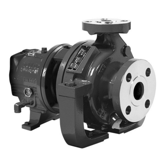
The model is based on 4 drive-unit sizes and 28 hydraulic sizes. Figure 5: HT 3196 pump This table shows the number of hydraulic sizes available for each drive-unit size group. Pump size group Number of hydraulic sizes XLT-i Model HT 3196 i-FRAME Installation, Operation, and Maintenance Manual... -
Page 17: Part Description Ht 3196
Standard flange ANSI class 300 raised-face serrated flange. Impeller The impeller is • fully open • screwed onto the shaft The threads are sealed from the pumped liquid by a graphite O-ring. Model HT 3196 i-FRAME Installation, Operation, and Maintenance Manual... -
Page 18: General Description I-Alert ™ Condition Monitor
The condition monitor enters alarm mode when either vibration or temperature limits are exceeded over two consecutive readings within a ten minute period. Alarm mode is indicated with two red flashing LEDs within two second intervals. Model HT 3196 i-FRAME Installation, Operation, and Maintenance Manual... -
Page 19: Nameplate Information
IECEx If applicable, your pump unit might have the following IECEx nameplate affixed to the pump and/or baseplate. The nameplate provides information about the IECEx specifications of this pump. Model HT 3196 i-FRAME Installation, Operation, and Maintenance Manual... - Page 20 Rated pump flow, in cubic meters per hour M HD Rated pump head, in meters Rated pump speed, in revolutions per minute MOD. Pump model SIZE Size of the pump STD. NO. ANSI standard designation Model HT 3196 i-FRAME Installation, Operation, and Maintenance Manual...
- Page 21 NOTICE: Make sure that the code classifications on the pump are compatible with the specific environment in which you plan to install the equipment. If they are not compatible, do not operate the equipment and contact your ITT representative before you proceed. Model HT 3196 i-FRAME Installation, Operation, and Maintenance Manual...
-
Page 22: Installation
Test the earth (ground) lead to verify that it is connected correctly. NOTICE: Supervision by an authorized ITT representative is recommended to ensure proper installation. Failure to do so may result in equipment damage or decreased performance. -
Page 23: Foundation Requirements
Use an epoxy primer only if you used an epoxy-based grout. Remove the rust-proofing coat from the machined mounting pads using an appropriate solvent. Remove water and debris from the foundation-bolt holes. Model HT 3196 i-FRAME Installation, Operation, and Maintenance Manual... -
Page 24: Install The Baseplate Using Shims Or Wedges
You can use the baseplate-leveling worksheet when you take the readings. Hand-tighten the nuts for the foundation. Install the baseplate using jackscrews Tools required: • Anti-seize compound • Jackscrews • Bar stock Model HT 3196 i-FRAME Installation, Operation, and Maintenance Manual... - Page 25 Use the baseplate-leveling worksheet when you take the readings. Machinist's levels Driver's mounting pads Foundation bolts Jackscrews Grout hole Pump's mounting pads Turn the center jackscrews down so that they rest on their plates on the foundation surface. Model HT 3196 i-FRAME Installation, Operation, and Maintenance Manual...
-
Page 26: Install The Baseplate Using Spring Mounting
Fasten the spring assembly with the upper adjusting nut by hand. Thread the upper jam nut onto the spring stud by hand. Repeat steps 2 through 4 for all the spring assemblies. Model HT 3196 i-FRAME Installation, Operation, and Maintenance Manual... -
Page 27: Install The Baseplate Using Stilt Mounting
Screw the upper jam nut onto the stilt by hand. Repeat steps 2 through 4 for all the stilt assemblies. Lower the baseplate so that the stilts fit into the foundation cups. Model HT 3196 i-FRAME Installation, Operation, and Maintenance Manual... - Page 28 Fasten the lower and upper jam nuts on each stilt. Mounting plate Mounting nut Stilt bolt Foundation cups Washer Upper adjustment nut Mounting washer Mounting bolt Figure 10: Example of an installed stilt assembly Model HT 3196 i-FRAME Installation, Operation, and Maintenance Manual...
-
Page 29: Baseplate-Leveling Worksheet
Installation Baseplate-leveling worksheet Level measurements 1)____________________ 2)____________________ 3)____________________ 4)____________________ 5)____________________ 6)____________________ 7)____________________ 8)____________________ 9)____________________ 10)___________________ 11)___________________ 12)___________________ 13)___________________ 14)___________________ 15)___________________ 16)___________________ 17)___________________ 18)___________________ Model HT 3196 i-FRAME Installation, Operation, and Maintenance Manual... -
Page 30: Install The Pump, Driver, And Coupling
After you connect the piping This ensures that pipe strains have not altered the alignment. If changes have occurred, you must alter the piping to remove pipe strains on the pump flanges. Model HT 3196 i-FRAME Installation, Operation, and Maintenance Manual... -
Page 31: Permitted Indicator Values For Alignment Checks
Attach two dial indicators on the pump coupling half (X): a) Attach one indicator (P) so that the indicator rod comes into contact with the perimeter of the driver coupling half (Y). This indicator is used to measure parallel misalignment. Model HT 3196 i-FRAME Installation, Operation, and Maintenance Manual... -
Page 32: Pump-To-Driver Alignment Instructions
Perform angular alignment for a horizontal correction Set the angular alignment indicator (A) to zero on left side of the driver coupling half (Y), 90° from the top-center position (9 o’clock). Model HT 3196 i-FRAME Installation, Operation, and Maintenance Manual... - Page 33 NOTICE: You must use an equal amount of shims with each driver foot to prevent misalignment. Failure to do so can result in equipment damage or decreased performance. Model HT 3196 i-FRAME Installation, Operation, and Maintenance Manual...
- Page 34 Rotate the indicators to the bottom-center position (6 o’clock). Record the indicator readings. Make corrections according to the separate instructions for angular and parallel alignment until you obtain the permitted reading values. Model HT 3196 i-FRAME Installation, Operation, and Maintenance Manual...
-
Page 35: C-Face Adapter
Required equipment: • Cleaners: Do not use an oil-based cleaner because the grout will not bond to it. See the instructions provided by the grout manufacturer. • Grout: Non-shrink grout is recommended. Model HT 3196 i-FRAME Installation, Operation, and Maintenance Manual... -
Page 36: Piping Checklists
• Vary the capacity with the regulating valve in the discharge line. Never throttle the flow from the suction side. This action can result in decreased performance, unexpected heat generation, and equipment damage. Model HT 3196 i-FRAME Installation, Operation, and Maintenance Manual... - Page 37 If the pump handles liquids at This helps to prevent misalignment due to linear elevated temperatures, make sure expansion of the piping. that the expansion loops and joints are properly installed. Model HT 3196 i-FRAME Installation, Operation, and Maintenance Manual...
-
Page 38: Suction-Piping Checklist
Install an eccentric reducer between the pump inlet and the suction piping. See the Example sections for illustrations. Model HT 3196 i-FRAME Installation, Operation, and Maintenance Manual... - Page 39 Make sure that the suction piping is This prevents air from entering the pump adequately submerged below the surface of through a suction vortex. the liquid source. Model HT 3196 i-FRAME Installation, Operation, and Maintenance Manual...
-
Page 40: Discharge Piping Checklist
The isolation valve is required for: installed in the discharge line. • Priming • Regulation of flow • Inspection and maintenance of the pump See Example: Discharge piping equipment for illustrations. Model HT 3196 i-FRAME Installation, Operation, and Maintenance Manual... - Page 41 Example: Discharge piping equipment Correct Incorrect Check valve (incorrect position) Bypass line The isolation valve should not be positioned Shut-off valve between the check valve and the pump. Check valve Discharge isolation valve Model HT 3196 i-FRAME Installation, Operation, and Maintenance Manual...
-
Page 42: Commissioning, Startup, Operation, And Shutdown
Remove the coupling guard Remove the nut, bolt, and washers from the slotted hole in the center of the coupling guard. Slide the driver half of the coupling guard toward the pump. Model HT 3196 i-FRAME Installation, Operation, and Maintenance Manual... - Page 43 Remove the nut, bolt, and washers from the driver half of the coupling guard. Remove the driver-side end plate. Driver-side end plate Driver Remove the driver half of the coupling guard: a) Slightly spread the bottom apart. b) Lift upwards. Model HT 3196 i-FRAME Installation, Operation, and Maintenance Manual...
- Page 44 Remove the pump half of the coupling guard: a) Slightly spread the bottom apart. b) Lift upwards. Annular groove Pump-side end plate Driver Pump half of the coupling guard Model HT 3196 i-FRAME Installation, Operation, and Maintenance Manual...
-
Page 45: Check The Rotation
0.021 (0.53) Up to 500°F (260°C) 0.012 (0.30) 0.015 (0.38) 0.022 (0.56) Up to 550°F (288°C) 0.013 (0.33) 0.016 (0.41) 0.023 (0.58) Up to 600°F (316°C) 0.014 (0.36) 0.017 (0.43) 0.024 (0.61) Model HT 3196 i-FRAME Installation, Operation, and Maintenance Manual... -
Page 46: Impeller-Clearance Setting
Loosen the jam nuts (423) on the jack bolts (370D) , and then back the bolts out about two turns. Tighten the locking bolts evenly (370C), bringing the bearing housing (134A) towards the frame (228) until the impeller contacts the casing. Model HT 3196 i-FRAME Installation, Operation, and Maintenance Manual... -
Page 47: Set The Impeller Clearance - Feeler Gauge Method (All Except Cv 3196)
(open and closed impeller) table. 11. Evenly tighten the locking bolts (370C) and then the adjuster bolts (371A) while keeping the indicator reading at the proper setting. 12. Make sure the shaft turns freely. Model HT 3196 i-FRAME Installation, Operation, and Maintenance Manual... -
Page 48: Couple The Pump And Driver
If the pump size is... Then... STi, MTi, LTi Align the pump-side end plate to the bearing frame. You do not need to adjust the impeller. Model HT 3196 i-FRAME Installation, Operation, and Maintenance Manual... - Page 49 Pump end plate Bearing housing Jam nut Put the pump-half of the coupling guard in place: a) Slightly spread the bottom apart. b) Place the coupling guard half over the pump-side end plate. Model HT 3196 i-FRAME Installation, Operation, and Maintenance Manual...
- Page 50 Use a bolt, a nut, and two washers to secure the coupling guard half to the end plate. Tighten securely. Washer Bolt Put the driver half of the coupling guard in place: a) Slightly spread the bottom apart. Model HT 3196 i-FRAME Installation, Operation, and Maintenance Manual...
- Page 51 The hole is located on the driver-side of the coupling guard half. Slide the driver-half of the coupling guard towards the motor so that the coupling guard completely covers the shafts and coupling. Model HT 3196 i-FRAME Installation, Operation, and Maintenance Manual...
-
Page 52: Bearing Lubrication
Oil volumes Oil volume requirements This table shows the required amount of oil for oil-lubricated bearings. Frame Qts. 1400 1400 XLT-i and i17 3000 Model HT 3196 i-FRAME Installation, Operation, and Maintenance Manual... - Page 53 Fill the bearing frame with oil through the filler connection, which is located on top of the bearing frame. Fill the bearing frame with oil until the oil level reaches the middle of the sight glass (319). Model HT 3196 i-FRAME Installation, Operation, and Maintenance Manual...
-
Page 54: Shaft-Sealing Options
Seal faces must have liquid film between them for proper lubrication. Locate the taps using the illustrations shipped with the seal. Seal flushing methods You can use these methods in order to flush or cool the seal: Model HT 3196 i-FRAME Installation, Operation, and Maintenance Manual... -
Page 55: Packed Stuffing Box Option
You must connect the piping to the lantern ring required. connection with a 40 to 60 drops-per-minute leak rate. The pressure must be 15 psi (1.01 kg/cm above the stuffing box pressure. Model HT 3196 i-FRAME Installation, Operation, and Maintenance Manual... -
Page 56: Pump Priming
Open the air vent valves in the casing. Open the valve in the outside supply line until only liquid escapes from the vent valves. Close the vent valves. Close the outside supply line. Model HT 3196 i-FRAME Installation, Operation, and Maintenance Manual... - Page 57 This illustration is an example of priming the pump with a foot valve using a bypass around the check valve: By-pass line Shutoff valve Foot valve Check valve Discharge isolation valve Model HT 3196 i-FRAME Installation, Operation, and Maintenance Manual...
-
Page 58: Other Methods Of Priming The Pump
Do not use the condition monitor in atmospheres containing acetic acid. The condition monitor is ready for activation when the pump is running and has reached a steady flow, pressure, and temperature. This process only takes a few minutes. Model HT 3196 i-FRAME Installation, Operation, and Maintenance Manual... -
Page 59: I-Alert ™ Condition Monitor Routine Operation
Commissioning, Startup, Operation, and Shutdown Place a small magnet on the condition monitor over the ITT logo and then remove it, as this example shows. Magnet 761B When the condition monitor is activated it: Displays a series of red LEDs followed by a solid green LED. -
Page 60: Pump Operation Precautions
You must handle and dispose of pumped fluid in compliance with the applicable environmental regulations. Slowly close the discharge valve. Shut down and lock the driver to prevent accidental rotation. Model HT 3196 i-FRAME Installation, Operation, and Maintenance Manual... -
Page 61: Deactivate The I-Alert ™ Condition Monitor
NOTICE: Always deactivate the condition monitor when the pump is going to be shut down for an extended period of time. Failure to do so will result in reduced battery life. Touch and hold a small magnet to the condition monitor over the ITT logo until the red LEDs blink three times. -
Page 62: Maintenance
• Check the pump power. If the pump performance does not satisfy your process requirements, and the process requirements have not changed, then perform these steps: Disassemble the pump. Inspect it. Replace worn parts. Model HT 3196 i-FRAME Installation, Operation, and Maintenance Manual... -
Page 63: Bearing Maintenance
Teresstic EP 68 Mobil DTE 26 300 SSU @ 100°F (38°C) Philips Mangus Oil 315 Shell Tellus Oil 68 Sunoco Sunvis 968 Royal Purple SYNFILM ISO VG 68 Synthetic Lube Brand Lubricant type Model HT 3196 i-FRAME Installation, Operation, and Maintenance Manual... -
Page 64: Regrease The Grease-Lubricated Bearings
The bearing temperature usually rises after you regrease due to an excess supply of grease. Temperatures return to normal in about two to four operating hours as the pump runs and purges the excess grease from the bearings. Model HT 3196 i-FRAME Installation, Operation, and Maintenance Manual... -
Page 65: Lubricate The Bearings After A Shutdown Period
Never operate the pump without liquid supplied to mechanical seal. If you run a mechanical seal dry, even for a few seconds, this can cause seal damage. Physical injury can occur if a mechanical seal fails. Model HT 3196 i-FRAME Installation, Operation, and Maintenance Manual... -
Page 66: Packed Stuffing-Box Maintenance
Wear the proper personal protective equipment. Potential hazards include, but are not limited to, high temperature, flammable, acidic, caustic, explosive, and other risks. You must handle and dispose of pumped fluid in compliance with the applicable environmental regulations. Model HT 3196 i-FRAME Installation, Operation, and Maintenance Manual... -
Page 67: Tools Required
Drain the liquid from the piping and flush the pump if it is necessary. Disconnect all auxiliary piping and tubing. Remove the coupling guard. Remove the coupling Disconnect the coupling. Remove the C-face adapter. Remove the coupling-guard pump end-plate. Model HT 3196 i-FRAME Installation, Operation, and Maintenance Manual... -
Page 68: Remove The Back Pull-Out Assembly
Remove the oil reservoir, if equipped. 408A NOTICE: Oil analysis should be part of a preventive maintenance program that determines the cause of a failure. Save the oil in a clean container for inspection. Model HT 3196 i-FRAME Installation, Operation, and Maintenance Manual... - Page 69 Remove the back pull-out assembly from the casing (100). Remove and discard the casing gasket. You will insert a new casing gasket during reassembly. Remove the jackscrews. Clean all gasket surfaces. Model HT 3196 i-FRAME Installation, Operation, and Maintenance Manual...
-
Page 70: Remove The Coupling Hub
To loosen the impeller, quickly turn it counter-clockwise (viewed from the impeller end of the shaft) while impacting the wrench handle on the workbench or a solid block. Model HT 3196 i-FRAME Installation, Operation, and Maintenance Manual... - Page 71 Clamp the frame foot (241) to the workbench when you use this method to remove the impeller. Remove the impeller plug (458Y) from the front of the impeller (101) and discard the Teflon gasket (428D). Model HT 3196 i-FRAME Installation, Operation, and Maintenance Manual...
- Page 72 If the impeller cannot be removed by the previous methods, cut the shaft between the gland and the frame, remove the impeller, stuffing-box cover, gland, sleeve, and shaft end as a unit. Do not apply heat. Model HT 3196 i-FRAME Installation, Operation, and Maintenance Manual...
-
Page 73: Seal-Chamber Cover Removal
Remove the rotary portion of the seal from the sleeve by loosening the setscrews and sliding it off the sleeve. Refer to the mechanical-seal instructions for more information. Remove the gland (250), the stationary portion of the seal, and the O-ring (360Q). 360Q Model HT 3196 i-FRAME Installation, Operation, and Maintenance Manual... -
Page 74: Remove The Stuffing-Box Cover (3196, Cv 3196, Ht 3196, Lf 3196, 3796)
Remove the stuffing-box cover (184). 370H 370H Remove the shaft sleeve (126). Remove the packing (106) and lantern ring (105) from the stuffing-box cover (184). A lantern ring does not come with self-lubricating graphite packing. Model HT 3196 i-FRAME Installation, Operation, and Maintenance Manual... -
Page 75: Remove The Frame Adapter (Mti, Lti , Xlt-I)
Remove the clamp screws (370C) and back off the jam nuts (423). Tighten the jack screws (370D) evenly to move the bearing housing (134) out of the bearing frame (228A). Remove the shaft assembly from the bearing frame (228A). Model HT 3196 i-FRAME Installation, Operation, and Maintenance Manual... - Page 76 Doing so may result in equipment damage. NOTICE: Save the bearings for inspection. Do not reuse the bearings. Doing so may result in decreased performance. Model HT 3196 i-FRAME Installation, Operation, and Maintenance Manual...
- Page 77 (134). You must remove the bearings before you can remove the clamp ring from the shaft. Remove the bearing housing (134) and the bearings (112A and 168A) from the shaft (122). Model HT 3196 i-FRAME Installation, Operation, and Maintenance Manual...
- Page 78 Remove the clamp screws (370C) and back off the jam nuts (423). Evenly tighten the jack screws (370D) to move the bearing housing (134) out of the bearing frame (228A). Remove the shaft assembly from the bearing frame (228A). Model HT 3196 i-FRAME Installation, Operation, and Maintenance Manual...
- Page 79 236A 253B Remove the bearing housing (134) and the bearings (112A and 168A) from the shaft (122). 253B 168A 112A Remove the bearing housing O-ring (496) and the inboard bearing (168A). Model HT 3196 i-FRAME Installation, Operation, and Maintenance Manual...
- Page 80 Labyrinth oil-seal O-rings are part of the 3196 maintenance kits, and they are sold separately. 497G 332A 497F Disassemble the power end ( XLT-i and i17 ) Remove the bearing frame from the frame foot (241) using the frame-foot bolts (370F). Model HT 3196 i-FRAME Installation, Operation, and Maintenance Manual...
- Page 81 Labyrinth oil-seal O-rings are part of the 3196 maintenance kits, and they are sold separately. 109A 332A 360C 371C 10. Remove the bearing housing (134) and the bearing (112A) from the shaft (122). Model HT 3196 i-FRAME Installation, Operation, and Maintenance Manual...
- Page 82 Tighten the jack screws (370D) evenly to move the bearing housing (134) out of the bearing frame (228A). Remove the shaft assembly from the bearing frame (228A). Remove the jack screws (370D) and the nuts (423). Remove the bearing housing O-ring (496) and the inboard bearing (168A). Model HT 3196 i-FRAME Installation, Operation, and Maintenance Manual...
- Page 83 Doing so may result in equipment damage. NOTICE: Save the bearings for inspection. Do not reuse the bearings. Doing so may result in decreased performance. Model HT 3196 i-FRAME Installation, Operation, and Maintenance Manual...
-
Page 84: Disassemble The Bearing Frame
Use these guidelines when disposing of the condition monitor. • The condition monitor is safe for disposal in the normal municipal waste stream. • Adhere to local laws when you dispose of the condition monitor. Model HT 3196 i-FRAME Installation, Operation, and Maintenance Manual... -
Page 85: Disassemble The C-Face Adapter
• Localized wear or grooving that is greater than 1/8 in. (3.2 mm) deep • Pitting that is greater than 1/8 in. (3.2 mm) deep • Irregularities in the casing-gasket seat surface Model HT 3196 i-FRAME Installation, Operation, and Maintenance Manual... - Page 86 Figure 19: Areas to inspect for wear on the 3196 impeller. Frame adapter check and replacement • Replace the frame adapter if it has cracks or excessive corrosion damage. • Make sure the gasket surface is clean. Model HT 3196 i-FRAME Installation, Operation, and Maintenance Manual...
-
Page 87: Shaft And Sleeve Replacement Guidelines
• If the frame has been exposed to pumped fluid, inspect the frame for corrosion or pitting. • Inspect the inboard-bearing bores. If any bores are outside the measurements in the Bearing fits and tolerances table, replace the bearing frame. Model HT 3196 i-FRAME Installation, Operation, and Maintenance Manual... -
Page 88: C-Face Adapter Inspection
• Check all surfaces for rust, scale, or debris and remove all loose and foreign material. • Check for corrosion or pitting. This figure shows the areas to inspect for cracks on the C-face adapter. Figure 22: C-face adapter inspection locations Model HT 3196 i-FRAME Installation, Operation, and Maintenance Manual... -
Page 89: Seal Chamber And Stuffing Box Cover Inspection
Replace the seal chamber and stuffing box cover if pitting or wear exceeds this measurement. • Inspect the machined surfaces and mating faces noted in the figures. These images point to the areas to inspect: Figure 23: BigBore chamber Figure 24: Stuffing box cover Model HT 3196 i-FRAME Installation, Operation, and Maintenance Manual... -
Page 90: Bearings Inspection
• Inspect the ball bearings to see if they are loose, rough, or noisy when you rotate them. • Investigate any bearing damage to determine the cause. If the cause is not normal wear, correct the issue before you return the pump to service. Model HT 3196 i-FRAME Installation, Operation, and Maintenance Manual... -
Page 91: Bearing-Housing Inspection
Clean the gasket surface. Inspection locations The following images point to the areas to inspect on the bearing housing. Figure 27: STi and MTi bearing housing Figure 28: LTi bearing housing Model HT 3196 i-FRAME Installation, Operation, and Maintenance Manual... -
Page 92: Bearing Fits And Tolerances
0.0000 (0.000) loose 0.0000 (0.000) loose 0.0000 (0.000) loose 0.0000 (0.000) loose Bearing OD 2.8346 (72.000) 3.9370 (100.000) 4.3307 (110.000) 5.5118 (140.000) Outboard 2.8341 (71.986) 3.9364 (99.985) 4.3301 (109.985) 5.5111 (139.982) Model HT 3196 i-FRAME Installation, Operation, and Maintenance Manual... -
Page 93: Reassembly
Wipe the preservative from the bearing (112) bore and outer diameter. e) Use an induction heater with a demagnetizing cycle to heat the bearing (112) to an inner ring temperature of 230 °F (110 °C). Model HT 3196 i-FRAME Installation, Operation, and Maintenance Manual... - Page 94 332A 361A 168A 10. Install the shaft assembly into the bearing frame as follows (see the illustration): Model HT 3196 i-FRAME Installation, Operation, and Maintenance Manual...
-
Page 95: Assemble The Rotating Element And The Bearing Frame ( Sti And Mti With Duplex Bearings)
Install four oil-mist connection plugs (408H). Or: Install two grease fittings (193) and two grease-relief plugs (113). h) Attach the bearing-frame foot (241) and fasten the bolts (370F) by hand. Model HT 3196 i-FRAME Installation, Operation, and Maintenance Manual... - Page 96 Place the bearing-clamp ring (253B) onto the shaft (122). Make sure that the orientation of the bearing-clamp ring is correct. Coat the inner surfaces of the bearings with lubricant. Put the inboard bearing (168) onto the shaft (122). Model HT 3196 i-FRAME Installation, Operation, and Maintenance Manual...
- Page 97 236A 253B 332A 11. Install the shaft assembly into the bearing frame as follows (see the illustration): Model HT 3196 i-FRAME Installation, Operation, and Maintenance Manual...
-
Page 98: Assemble The Rotating Element And The Bearing Frame ( Lti )
NOTICE: The oil flinger is press fitted onto the shaft. Use a properly sized driver. Failure to do so may result in damage to the oil flinger. Place the bearing-clamp ring (253B) onto the shaft (122). Model HT 3196 i-FRAME Installation, Operation, and Maintenance Manual... - Page 99 Coat the outside of the outboard bearing (112A) with oil. b) Coat the bore of the bearing housing (134) with oil. c) Put the bearing housing (134) onto the shaft. Do not use force. Model HT 3196 i-FRAME Installation, Operation, and Maintenance Manual...
- Page 100 Install the clamp bolts (370C) in the bearing housing (134) and tighten by hand. e) Install the jack bolts (370D) with the locknuts (423) in the bearing housing (134) and tighten by hand. 228A 370D 370C Model HT 3196 i-FRAME Installation, Operation, and Maintenance Manual...
-
Page 101: Assemble The Rotating Element And The Bearing Frame ( Xlt-I And I17 )
Position the bearing (112) on the shaft (122) against the shoulder and snug the locknut (136) against the bearing until it is cool. The locknut prevents the bearing from moving away from the shaft shoulder as it cools. Model HT 3196 i-FRAME Installation, Operation, and Maintenance Manual... - Page 102 Put the inboard bearing (168) onto the shaft (122). The regreasable bearing has a single shield. Make sure that the bearing is installed with the shield away from the impeller. Model HT 3196 i-FRAME Installation, Operation, and Maintenance Manual...
- Page 103 Install the jack bolts (370D) with the locknuts (423) in the bearing housing (134) and tighten by hand. f) Attach the bearing-frame foot (241) and fasten the bolts (370F) by hand. 228A 370D 370C Model HT 3196 i-FRAME Installation, Operation, and Maintenance Manual...
-
Page 104: Assemble The Rotating Element And The Bearing Frame ( Xlt-I And I17 With Duplex Bearings)
The duplex bearings are mounted back-to-back. Make sure that the orientation of the bearings are correct. a) Inspect the shaft (122) to ensure that it is clean, dimensionally correct, and is free of nicks and burrs. Model HT 3196 i-FRAME Installation, Operation, and Maintenance Manual... - Page 105 Put the bearing housing (134) onto the shaft. Do not use force. Fasten the gasket (360C) and the end cover (109A) with the bolts (371C). See the specified torque values. Make sure that the shaft rotates freely. Model HT 3196 i-FRAME Installation, Operation, and Maintenance Manual...
- Page 106 Install the jack bolts (370D) with the locknuts (423) in the bearing housing (134) and tighten by hand. f) Attach the bearing-frame foot (241) and fasten the bolts (370F) by hand. Model HT 3196 i-FRAME Installation, Operation, and Maintenance Manual...
-
Page 107: Assemble The Frame
MTi inches (millimeters) 0.0021 (0.053) 0.0012 (0.030) Not applicable 0.0010 (0.025) LTi inches (millimeters) 0.0015 (0.038) 0.0014 (0.036) 0.0010 (0.025) XLT-i inches (millimeters) 0.0023 (0.058) 0.0015 (0.038) Check the shaft-sleeve (126) runout. Model HT 3196 i-FRAME Installation, Operation, and Maintenance Manual... - Page 108 Place the frame adapter (108) onto the frame assembly. SCALE 0.150 b) Align the bolt holes and dowel locations on the frame adapter with the bolt holes and dowel locations on the frame. Model HT 3196 i-FRAME Installation, Operation, and Maintenance Manual...
- Page 109 The labyrinth oil seal is an O-ring fit. Position the labyrinth oil-seal drain slots at the bottom (6 o’clock) position. Refer to Assemble the INPRO labyrinth oil-seal for more information on the labyrinth oil-seal installation. Model HT 3196 i-FRAME Installation, Operation, and Maintenance Manual...
-
Page 110: Inpro Labyrinth Oil Seal Description
Rotor drive ring Stator gasket Expulsion port D groove Lube return Location shoulder Assemble the INPRO labyrinth oil seal Wrap electrical tape around the coupling end of the shaft to cover the keyway. Model HT 3196 i-FRAME Installation, Operation, and Maintenance Manual... -
Page 111: Assemble The C-Face Adapter
• Seal the shaft with a cartridge-mechanical seal. • Seal the shaft with a conventional inside-component mechanical seal. • Seal the shaft with a conventional outside-component mechanical seal. • Seal the shaft with a packed stuffing box. Model HT 3196 i-FRAME Installation, Operation, and Maintenance Manual... - Page 112 Slide the cartridge seal onto the shaft or sleeve until it contacts the inboard labyrinth oil seal. Assemble the seal chamber. Slide the cartridge seal into the seal chamber and secure using the four studs and nuts. Continue with the pump reassembly. Model HT 3196 i-FRAME Installation, Operation, and Maintenance Manual...
- Page 113 Assemble the seal chamber: a) Install a seal-chamber cover or a backplate (184) and fasten with nuts (370H) with . 370H b) Check the seal-chamber cover runout. Model HT 3196 i-FRAME Installation, Operation, and Maintenance Manual...
- Page 114 The mechanical seal must have an appropriate seal-flush system. Otherwise, excess heat generation and seal failure can occur. Assemble the seal chamber. a) Install the seal-chamber cover or backplate (184) and fasten with nuts (370H). Model HT 3196 i-FRAME Installation, Operation, and Maintenance Manual...
- Page 115 Rotate the indicator through 360 degrees. If the total indicator reading is greater than 0.005 in. (0.13 mm), determine the cause and correct the issue before you proceed. c) Install the shaft sleeve (126). Model HT 3196 i-FRAME Installation, Operation, and Maintenance Manual...
-
Page 116: Install The Impeller
(counterclockwise, viewed from the impeller end of the shaft) off of the bench and slam it down (clockwise, viewed from the impeller end of shaft). b) Apply a few sharp raps to tighten the impeller (101). Model HT 3196 i-FRAME Installation, Operation, and Maintenance Manual... - Page 117 Check the impeller (101) runout. Check vane tip to vane tip. If the total indicator reading is greater than 0.005 in. (0.13 mm), determine the cause and correct the issue before you proceed. Model HT 3196 i-FRAME Installation, Operation, and Maintenance Manual...
-
Page 118: Attach The I-Alert ™ Condition Monitor To The Pump
Attach the condition monitor (761B) to the bearing frame (228A) using the hex-head screw (372T) provided. 372T 761B 228A Tighten the hex-head screw with a 5/32 inch hex wrench to 6 ft-lbs (8 Nm). Model HT 3196 i-FRAME Installation, Operation, and Maintenance Manual... -
Page 119: Post-Assembly Checks
STi, MTi 10* (1.1) 17* (1.9) 10* (1.1) 17* (1.9) 10* (1.1) 17* (1.9) bolts (236A) - duplex 55* (6.2) 83* (9.4) 55* (6.2) 83* (9.4) 55* (6.2) 83* (9.4) bearing only Model HT 3196 i-FRAME Installation, Operation, and Maintenance Manual... - Page 120 0.0014 (0.036) 0.0010 (0.025) XLT-i inches (millimeters) 0.0023 (0.058) 0.0015 (0.038) Bearing types Table 20: Bearing types Outboard bearing Frame Inboard bearing Double row Duplex 6207 3306 7306 6309 3309 7309 Model HT 3196 i-FRAME Installation, Operation, and Maintenance Manual...
-
Page 121: Spare Parts
Seal Chamber Impeller Casing Size Description Frame Assembly 1x1.5-6 AA 1.5x3-6 AB Model HT 3196 2x3-6 AC STi 1–3/8 in. 1x1.5-8LF AA Shaft Dia. Max 1X1.5-8 AA BHP-40 HP 1.5X3-8 AB Model HT 3196 i-FRAME Installation, Operation, and Maintenance Manual... -
Page 122: Lubrication Conversion
This table shows which brand of grease to use when lubricating the pump. Table 22: Lubricating-grease requirements Pumpage temperature less than Pumpage temperature greater 350°F (177°C) than 350°F (177°C) NGLI consistency Mobil Mobilux EP2 SCH32 Model HT 3196 i-FRAME Installation, Operation, and Maintenance Manual... -
Page 123: Convert From Greased-For-Life Or Regreaseable To Oil-Lubricated Bearings
Two plugs (408H) are required to replace the two grease fittings. 408W 113A 372T 408W 761B 408N 228A 408M 408L 408A 370F Item Number Size Description Quantity 1/4"-18 NPT External hex/square head pipe plug Model HT 3196 i-FRAME Installation, Operation, and Maintenance Manual... -
Page 124: Conversion From Flood-Oil To Pure-Oil Mist
Light helical spring lock washer Conversion from flood-oil to pure-oil mist Consult your local ITT representative for further information on this topic. Convert from flood oil to regreaseable Consult your local ITT representative for further information on this topic. Model HT 3196 i-FRAME Installation, Operation, and Maintenance Manual... -
Page 125: Troubleshooting
The suction or discharge piping is not anchored Anchor the suction or discharge piping as necessary according to recommendations in the or properly supported. Hydraulic Institute Standards Manual. Locate and correct the system problem. The pump is cavitating. Model HT 3196 i-FRAME Installation, Operation, and Maintenance Manual... -
Page 126: Alignment Troubleshooting
There is corrosion or wear on the seal Replace the seal chamber or stuffing- chamber or stuffing-box cover. box cover. There is excessive vane-tip runout of the The vane is bent. Replace the impeller. impeller. Model HT 3196 i-FRAME Installation, Operation, and Maintenance Manual... -
Page 127: I-Alert ™ Condition Monitor Troubleshooting
The red LEDs are flashing, but the temperature and vibration are at acceptable levels. vibration levels and reset the condition monitor. The unit is malfunctioning. Consult your ITT representative for a warranty replacement. Model HT 3196 i-FRAME Installation, Operation, and Maintenance Manual... -
Page 128: Parts Listings And Cross-Sectional Drawings
Inboard Labyrinth Seal w/O-rings Brass ASTM B505-96 Casing Gasket Aramid fiber w/EPDM Gland Stud 2228 Gland Stud Nut 2228 Plug—Casing Drain 2210 2229 2230 358Y 1 *** Plug, Impeller 2229 2230 Model HT 3196 i-FRAME Installation, Operation, and Maintenance Manual... - Page 129 O-Ring—Impeller Viton 497F 1 O-Ring—Outboard Labyrinth Rotor Viton 497G 1 O-Ring—Outboard Labyrinth Stator Viton 497H 1 O-Ring—Inboard Labyrinth Rotor Viton 497J O-Ring—Inboard Laybrinth Stator Viton 497L 1 O-Ring Internal (inboard) Viton Model HT 3196 i-FRAME Installation, Operation, and Maintenance Manual...
- Page 130 Cap Screw—Bearing Clamp Ring 2210 Support, Casing – – – 2201* – Frame Foot 1001 Oil Thrower 2210 Gland—Mechanical Seal Material varies 253B 1 Bearing Clamp Ring 2210 Sight Glass Glass/steel Model HT 3196 i-FRAME Installation, Operation, and Maintenance Manual...
- Page 131 – 458Y 1*** Plug, Impeller 2232 2150 2155 2248 2247 469B 2 Dowel Pin—Frame-to-Adapter Steel Tube Element, Finned Cooled 304SS / Copper O-Ring Bearing Housing Buna N 412A 1 O-Ring—Impeller Viton Model HT 3196 i-FRAME Installation, Operation, and Maintenance Manual...
- Page 132 168A 1 Radial Bearing Single row ball Seal Chamber/Stuffing Box Cover 1220 6929 9639 Grease Fitting Steel Bearing Frame 236A 10 Cap Screw—Bearing Clamp Ring 2210 Support, Casing – – – Model HT 3196 i-FRAME Installation, Operation, and Maintenance Manual...
- Page 133 408N 1 Plug—Sight Glass 2210 412A 1 O-Ring, Graphoil Impeller – – – Jack Bolt—Adapter-to-Case 2228 Jam Nut—Bearing Housing Jack Bolt 2210 423B 2 Hex Nut—Stuffing Box Cover to 2228 Adapter Model HT 3196 i-FRAME Installation, Operation, and Maintenance Manual...
- Page 134 12 for 10 in. MTi, LTi , i17 Table 28: Material-code reference Material Goulds material ASTM code Cast Iron 1001 A48 CLASS 20 Ductile Iron 1012 A395 Gr60-40-18 Ductile Iron 1013 A536 Gr60-42-10 CD4MCu 1041 A744 CD4MCU Model HT 3196 i-FRAME Installation, Operation, and Maintenance Manual...
- Page 135 4140 Steel 2239 A193 Gr. B7 Alloy B-2 2247 B335 (N10665) Alloy C-276 2248 B574 (N10276) GMP-2000 6929 PFA Lined Steel 6944 PFA Lined 316SS 6947 PFA Lined Ductile 9639 Iron Model HT 3196 i-FRAME Installation, Operation, and Maintenance Manual...
- Page 136 HT 3196. See power frame exploded view drawing. Figure 30: HT 3196 cross-sectional drawing 372T 408W 761B 408W 113A 408N 333A 408L 361A 370D 497H 332A 497J 112A 408L 370C 497F 497G Figure 31: STi bearing-frame exploded view Model HT 3196 i-FRAME Installation, Operation, and Maintenance Manual...
- Page 137 Figure 32: MTi bearing-frame exploded view 372T 761B 408W 408N 113A 408M 408W 168A 228A 253B 317B 370D 497G 408L 236A 408A 112A 370F 370C 332A 497F Figure 33: LTi bearing-frame exploded view Model HT 3196 i-FRAME Installation, Operation, and Maintenance Manual...
- Page 138 Figure 34: XLT-i bearing-frame exploded view The finned-tube oil cooler is standard on HT 3196 and optional on all other models. 555C 555B 551D 555B 555C Figure 35: Finned-tube oil cooler exploded view Model HT 3196 i-FRAME Installation, Operation, and Maintenance Manual...
-
Page 139: Certification: Ce Or Ce Atex
Certification: CE or CE ATEX Certification: CE or CE ATEX Certificates of conformance CSA Certificate Model HT 3196 i-FRAME Installation, Operation, and Maintenance Manual... - Page 140 Certification: CE or CE ATEX Model HT 3196 i-FRAME Installation, Operation, and Maintenance Manual...
- Page 141 Certification: CE or CE ATEX ATEX notification Model HT 3196 i-FRAME Installation, Operation, and Maintenance Manual...
- Page 142 Certification: CE or CE ATEX IECEx Certificate of Conformity Model HT 3196 i-FRAME Installation, Operation, and Maintenance Manual...
- Page 143 Certification: CE or CE ATEX Model HT 3196 i-FRAME Installation, Operation, and Maintenance Manual...
- Page 144 Certification: CE or CE ATEX Chinese Certificate of Conformity Model HT 3196 i-FRAME Installation, Operation, and Maintenance Manual...
-
Page 145: Other Relevant Documentation Or Manuals
Other Relevant Documentation or Manuals Other Relevant Documentation or Manuals For additional documentation For any other relevant documentation or manuals, contact your ITT representative. Model HT 3196 i-FRAME Installation, Operation, and Maintenance Manual... -
Page 146: Local Itt Contacts
Camino La Colina # 1448 Condominio Industrial El Rosal Huechuraba – Santiago 8580000 Chile Middle East and Africa ITT - Goulds Pumps +30–210–677–0770 +30–210–677–5642 Achileos Kyrou 4 Neo Psychiko 115 25 Athens Greece Model HT 3196 i-FRAME Installation, Operation, and Maintenance Manual... - Page 148 Visit our Web site for the latest version of this document and more information http://www.gouldspumps.com 240 Fall Street Seneca Falls, NY 13148 Tel. 1–800–446–8537 Fax (315) 568–2418 © 2010 ITT Corporation. The original instruction is in English. All non-English instructions are translations of the original instruction. en-US.2011-04.IOM.HT3196.i-FRAME...
Need help?
Do you have a question about the HT 3196 i-FRAME and is the answer not in the manual?
Questions and answers