Table of Contents
Advertisement
4280 E 14
DES MOINES, IOWA 50313
PH: 515-265-2222/FAX: 515-265-6608
CLINTON, IA BEAVER CHANNEL PS
SECTION 11076: SUBMERSIBLE PUMPS
TAG: CSO WET WELL PUMP 11CSO-P04
TAG: SUBSURFACE DRAIN PUMPS 23SD-P01
TAG: BASIN DRAIN PUMP 23BD-P01
TAG:CLARIFIER SCUM PUMPS 25SCM-P01 & 02
TAG: AREATION BASIN SCUM PUMPS 23SCM-P01 & 02
OPERATION AND MAINTENANCE MANUAL
HDR ENGINEERING, INC.
8404 INDIAN HILLS DRIVE
OMAHA, NE 68114
GRIDOR CONSTRUCTION, INC.
3990 – 27
BUFFALO, MN 55313
ELECTRIC PUMP
4280 E. 14
DES MOINES, IOWA 50313
DATE: MAY 25, 2011
STREET
TH
ENGINEER
402-399-1280
CONTRACTOR
STREET, S.E
TH
763-746-9075
SUPPLIER
STREET
TH
800-383-7867
Advertisement
Chapters
Table of Contents

Related Manuals for ITT Flygt 3127


Summary of Contents for ITT Flygt 3127
- Page 1 4280 E 14 STREET DES MOINES, IOWA 50313 PH: 515-265-2222/FAX: 515-265-6608 CLINTON, IA BEAVER CHANNEL PS SECTION 11076: SUBMERSIBLE PUMPS TAG: CSO WET WELL PUMP 11CSO-P04 TAG: SUBSURFACE DRAIN PUMPS 23SD-P01 TAG: BASIN DRAIN PUMP 23BD-P01 TAG:CLARIFIER SCUM PUMPS 25SCM-P01 & 02 TAG: AREATION BASIN SCUM PUMPS 23SCM-P01 &...
- Page 2 TABLE OF CONTENTS DESCRIPTION SECTION CLINTON, IA BEAVER CHANNEL SECTION 11076: SUBMERSIBLE NON CLOG PUMPS / BASIN DRAIN & SURFACE DRAIN PUMPS / AREATION BASIN & CLARIFIER SCUM PUMPS Flygt Submersible Non Clog Pumps TAG: CSO WET WELL PUMP 11CSO-P04 Installation, Operation and Maintenance Manual Model No.
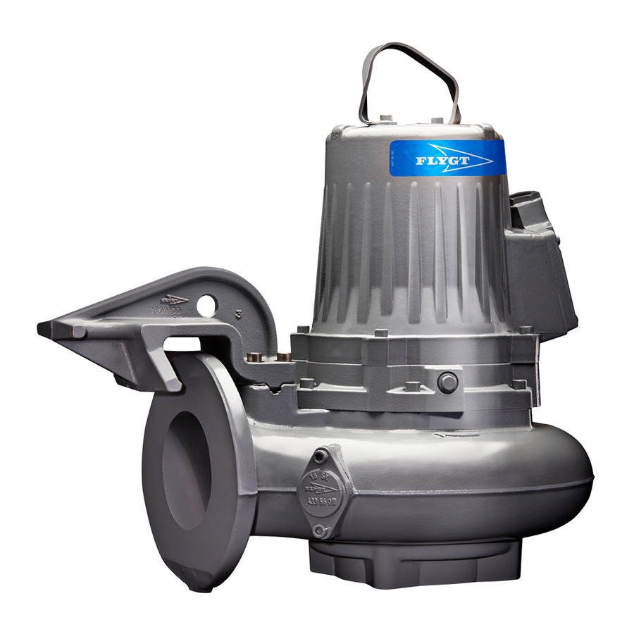
- Page 3 Water & Wastewater TAG: CSO WET WELL PUMP 11CSO-P04 Installation, Operation, and Maintenance Manual Flygt 3127...
-
Page 5: Table Of Contents
Connect the motor cable to the pump........................20 Connect the motor cable to the starter and monitoring equipment..............21 Cable charts...................................22 Check the impeller rotation............................28 Operation...................................29 Precautions..................................29 Distance to wet areas..............................29 Noise level..................................29 Start the pump.................................29 Flygt 3127 Installation, Operation, and Maintenance Manual... - Page 6 The pump does not stop when a level sensor is used....................54 The pump starts-stops-starts in rapid sequence......................54 The pump runs but the motor protection trips......................54 The pump delivers too little or no water........................55 Technical Reference................................57 Motor data..................................57 Application limits................................57 Flygt 3127 Installation, Operation, and Maintenance Manual...
-
Page 7: Introduction And Safety
• All service and repair work is done by ITT-authorized personnel. • Genuine ITT parts are used. • Only Ex-approved spare parts and accessories authorized by ITT are used in Ex-approved products. Limitations The warranty does not cover faults caused by these situations: •... -
Page 8: Safety
This includes any modification to the equipment or use of parts not provided by ITT. If there is a question regarding the intended use of the equipment, please contact an ITT representative before proceeding. -
Page 9: User Safety
Electrical connections Electrical connections must be made by certified electricians in compliance with all international, national, state, and local regulations. For more information about requirements, see sections dealing specifically with electrical connections. Flygt 3127 Installation, Operation, and Maintenance Manual... -
Page 10: Ex-Approved Products
ATEX compliance is fulfilled only when you operate the unit within its intended use. Do not change the conditions of the service without the approval of an ITT representative. When you install or maintain ATEX- compliant equipment, always comply with the directive and applicable standards in IEC/EN 60079–14. -
Page 11: Environmental Safety
Follow local laws and regulations regarding recycling if the unit or parts are accepted by an authorized recycling company. If the first guideline is not applicable, then return the unit or parts to your ITT representative. Waste and emissions regulations Observe these safety regulations regarding waste and emissions: •... -
Page 12: Transportation And Storage
Lifting equipment Lifting equipment is always required when handling the pump. It must fulfill the following requirements: • The minimum height (contact ITT for information) between the lifting hook and the floor must be sufficient to lift the pump. • The lifting equipment must be able to hoist the pump straight up and down, preferably without the need for resetting the lifting hook. -
Page 13: Freezing Precautions
• Before operating the pump after storage, it must be inspected with special attention to the seals and the cable entry. • The impeller/propeller must be rotated every other month to prevent the seals from sticking together. Flygt 3127 Installation, Operation, and Maintenance Manual... -
Page 14: Product Description
• Modifications to the unit or installation should only be carried out after consulting with ITT. • Original spare parts and accessories authorized by ITT are essential for compliance. The use of other parts can invalidate any claims for warranty or compensation. For more information contact your ITT representative. -
Page 15: Parts
The bearing consisting of a two-row angular contact ball bearing. Motor For information about the motor, see Motor data (page 57). Stator housing The pump is cooled by the ambient liquid/air. Support bearing The bearing consisting of a single-row ball bearing. Flygt 3127 Installation, Operation, and Maintenance Manual... -
Page 16: Monitoring Equipment
Product denomination (page 14) Product number Country of origin Additional information Phase; type of current; frequency Rated voltage Thermal protection Thermal class 10. Rated shaft power 11. International standard 12. Degree of protection Flygt 3127 Installation, Operation, and Maintenance Manual... -
Page 17: Approvals
Approvals This section describes the EN and FM approvals that explosion-proof products have. For more information, please contact your ITT representative. In addition to the data plate, explosion-proof products also have either an EN or a FM approval plate. • European Norm •... -
Page 18: Product Denomination
The serial number is used for identification of an individual product, and is divided into four parts. This is an example of a serial number, and an explanation of its parts. NP 3085.183 - 951 0163 Product code Production year Production cycle Running number Flygt 3127 Installation, Operation, and Maintenance Manual... -
Page 19: Installation
Fasteners WARNING: • Only use fasteners of the proper size and material. • Replace all corroded fasteners. • Make sure that all fasteners are properly tightened and that there are no missing fasteners. Flygt 3127 Installation, Operation, and Maintenance Manual... -
Page 20: Install With P-Installation
Fasten the permanent lifting device to the pump and to the access frame. For example, you can use a stainless-steel lifting chain with shackles. b) Fasten the cable to the cable holder. Flygt 3127 Installation, Operation, and Maintenance Manual... -
Page 21: Install With S-Installation
• In the Z-installation, the pump is installed in a horizontal position on a support stand in a dry well next to the wet sump. The following requirements and instructions are for Z-installations that comply to the dimensional drawing. Flygt 3127 Installation, Operation, and Maintenance Manual... -
Page 22: Make The Electrical Connections
• Make sure that all unused conductors are insulated. • There is a risk of electrical shock or explosion if the electrical connections are not correctly carried out or if there is fault or damage on the product. Flygt 3127 Installation, Operation, and Maintenance Manual... -
Page 23: Requirements
If the outer sheath of the cable is damaged, then replace the cable. Contact an ITT service shop. • The voltage drop in long cables must be taken into account. The drive unit’s rated voltage is the voltage measured at the terminal board in the upper part of the pump. -
Page 24: Connect The Motor Cable To The Pump
Make sure that any thermal contacts incorporated in the pump are properly connected to the terminal block/closed end splices. Install the entrance cover and the O-ring on the stator housing. Fasten the screws on the entrance flange so that the cable insertion assembly bottoms out. Flygt 3127 Installation, Operation, and Maintenance Manual... -
Page 25: Connect The Motor Cable To The Starter And Monitoring Equipment
Check the functionality of the monitoring equipment: a) Check that the signals and the tripping function work properly. b) Check that the relays, lamps, fuses, and connections are intact. Replace any defective equipment. Flygt 3127 Installation, Operation, and Maintenance Manual... -
Page 26: Cable Charts
White T2 Blue White T2 – – White T3 – – White T4 Colors of the stator leads Stator connection Lead color Green (Brown if 1 phase stator 4 leads is used) Green Flygt 3127 Installation, Operation, and Maintenance Manual... - Page 27 This table shows the connection diagrams for example the SUBCAB 4GX. T1 T2 SUBCAB 4GX/SUBCAB AWG/SI-SL-BIHF, 12 stator leads, 230V, 1 phase This table shows the connection diagrams for example the SUBCAB 4GX. Flygt 3127 Installation, Operation, and Maintenance Manual...
- Page 28 T1 T2 T1 T2 V1 U2 SUBCAB 7GX, 2 motor cables, 6 stator leads, D connection This table shows the connection diagrams for the SUBCAB 7GX (3-phase power cables), with D serial connection. Flygt 3127 Installation, Operation, and Maintenance Manual...
- Page 29 T1 T2 U2 W2 SUBCAB 4GX/SUBCAB AWG, 9-leads, 230/460 V, Y connection This table shows the connection diagrams for example the SUBCAB 4GX (3-phase power cables), with Y parallel/serial connection (60 Hz only). Flygt 3127 Installation, Operation, and Maintenance Manual...
- Page 30 T1 T2 SUBCAB Screened S3X2.5+3X2.5/3+4X1.5, 6 stator leads, Y and D connection This table shows the connection diagrams for the SUBCAB Screened (3-phase power cable), with Y parallel/ serial connection (60 Hz only). Flygt 3127 Installation, Operation, and Maintenance Manual...
- Page 31 36 mA Leakage The values have a 10 % tolerance CLS and Thermal contact (only standard version) Value 0 mA Overtemperature 5.5mA 29mA Leakage (5 second delay) The values have a 10 % tolerance Flygt 3127 Installation, Operation, and Maintenance Manual...
-
Page 32: Check The Impeller Rotation
If the impeller rotates in the wrong direction, do one of these steps: • If the motor has a 1-phase connection, contact the local ITT shop. • If the motor has a 3-phase connection, transpose two phase leads and do this procedure again. -
Page 33: Operation
Remove the fuses or open the circuit breaker, and check that the impeller can be rotated freely. Conduct insulation test phase to ground. To pass, the value must exceed 5 megohms. Check that the monitoring equipment works. Start the pump. Flygt 3127 Installation, Operation, and Maintenance Manual... -
Page 34: Maintenance
9.3 (6.9) 22 (16) 44 (32) 76 (56) 187 (138) 364 (268) 629 (464) 1240 Nm (ft- (915) lbs) Carbon steel and alloyed steel Property class 70 is torque tightened as class 80. Flygt 3127 Installation, Operation, and Maintenance Manual... -
Page 35: Change The Oil
Place the pump in a horizontal position and unscrew the oil plug. If the pump has a hole with the markings "oil out" it is important that this hole is used for drainage. Flygt 3127 Installation, Operation, and Maintenance Manual... -
Page 36: Fill With Oil
Fill with oil through the hole on the opposite side or the hole marked "oil in". If the hole is marked "oil in", slightly tilt the pump and lower it again in order to fill the pump with the correct quantity. Quantity: approximately 2.0 liters (2.1 quarts) Flygt 3127 Installation, Operation, and Maintenance Manual... -
Page 37: Replace The Impeller
• 10 mm hexagon-bit adaptor with an extension of at least 125 mm (4.92 in.) or an extended hexagon bit with the same measurement • Impeller puller If applicable, contact your local ITT representative for correct type and size. • A wooden or copper rod for locking the impeller in place, if applicable. • Two crowbars, if applicable WARNING: •... -
Page 38: Replace The C- Or D-Impeller
Remove the C- or D-impeller CAUTION: A worn impeller and/or pump housing can have very sharp edges. Wear protective gloves. Remove the pump housing or the suction cover. Remove the impeller screw. If applicable, use the rod. Flygt 3127 Installation, Operation, and Maintenance Manual... - Page 39 Do NOT grease the conical part of the shaft. Mount the impeller: a) Fit the washer on the lubricated impeller screw. b) Press the impeller onto the shaft with the impeller screw. Tighten the impeller screw. If applicable, use the rod. Flygt 3127 Installation, Operation, and Maintenance Manual...
- Page 40 Mount the pump housing: a) D-impeller (only 3127.170, 3127.890): Fit a new lubricated O-ring to the pump housing. b) Fit the pump housing. c) Fit and tighten the lubricated screws. Tightening torque: 57 Nm (42 ft-lbs). Flygt 3127 Installation, Operation, and Maintenance Manual...
-
Page 41: Replace The F-Impeller
CAUTION: A worn impeller and/or pump housing can have very sharp edges. Wear protective gloves. Remove the suction cover. Remove the impeller screw, the ring, and the washers. If applicable, use the rod. Flygt 3127 Installation, Operation, and Maintenance Manual... - Page 42 Fasten the impeller: a) Prevent the impeller from rotating by inserting the rod through the pump housing outlet. b) Tighten the impeller screw. If applicable, use the rod. Tightening torque: 80 Nm (59 ft-lbs) Flygt 3127 Installation, Operation, and Maintenance Manual...
- Page 43 Use Loctite 603 locking liquid in order to secure the studs. b) Fit one adjustment washer with a thickness of 1.5 mm (0.06 in.) and 7-8 adjustment washers with a thickness of 0.3 mm (0.01 in.) onto each stud. Flygt 3127 Installation, Operation, and Maintenance Manual...
- Page 44 Use adjustment washers with a thickness of 1.5 mm (0.06 in.) and 0.3 mm (0.01 in.) in order to achieve the correct distance. b) Tighten the nuts. Tightening torque: 57 Nm (42 ft-lbs). Flygt 3127 Installation, Operation, and Maintenance Manual...
-
Page 45: Replace The H-Impeller
If applicable, use the rod. Remove the impeller from the shaft: a) Insert a M16 screw into the square nut. b) Turn the screw to push off the impeller. Remove the screw and the square nut. Flygt 3127 Installation, Operation, and Maintenance Manual... -
Page 46: Replace The M-Impeller
Remove the M-impeller CAUTION: A worn impeller and/or pump housing can have very sharp edges. Wear protective gloves. Remove the pump housing. Remove the impeller screw and outer sleeve. If applicable, use the rod. Flygt 3127 Installation, Operation, and Maintenance Manual... - Page 47 Fit the impeller puller and pull off the impeller and cutter wheel. • If used, remove the washer between the impeller and cutter wheel. Place a protector between the screw head and the impeller puller. Remove the conical sleeve. Flygt 3127 Installation, Operation, and Maintenance Manual...
- Page 48 LT, HT 65.0±0.3 mm (2.56±0.01 in.) LT, HT 65.0±0.3 mm (2.56±0.01 in.) 63.0±0.3 mm (2.48±0.01 in.) 65.0±0.3 mm (2.56±0.01 in.) b) Slide the impeller on to the shaft until you reach the correct distance. Flygt 3127 Installation, Operation, and Maintenance Manual...
- Page 49 Tightening torque: 80 Nm (59 ft-lbs) Check that the impeller can rotate freely. Mount the pump housing: a) Fit the pump housing. b) Fit and tighten the lubricated screws. Tightening torque: 57 Nm (42 ft-lbs). Flygt 3127 Installation, Operation, and Maintenance Manual...
-
Page 50: Replace The N-Impeller
1.5 (0.06) T, Z 1.5 (0.06) The total thickness is (A) 4.5 mm (0.18 in.) Mount the impeller: a) Fit the washer on the lubricated impeller screw. b) Fit the impeller to the shaft. Flygt 3127 Installation, Operation, and Maintenance Manual... - Page 51 For P-, S-, and L-installation, adjust the impeller: a) Measure the distance (C) between the lower edge of the impeller and the insert ring. The correct distance (C) is 0.2-0.8 mm (0.0079-0.032 in.). Flygt 3127 Installation, Operation, and Maintenance Manual...
- Page 52 Tightening torque: For pressure class: • LT, MT, HT: 80 Nm (59ft-lbs) • SH: 35 Nm (26 ft-lbs) f) Fit the pump housing. g) Fit and tighten the lubricated screws. Tightening torque: 57 Nm (42 ft-lbs). Flygt 3127 Installation, Operation, and Maintenance Manual...
-
Page 53: Replace The Propeller
• A wooden or copper rod for locking the propeller in place, if applicable • Impeller puller If applicable, contact your local ITT representative for correct type and size. • Two crowbars, if applicable WARNING: •... -
Page 54: Install The Propeller
• Permanent: 3 years • Portable: once a year • For hot water applications (≤ 70°C [160°F]) with these mode of operation: • Intermittent: once a year • Continuous: every 4000 hours Intermediate service Flygt 3127 Installation, Operation, and Maintenance Manual... -
Page 55: Major Service
For information about indication values for sensors, see Sensor connection. Alarm source Action Check for water in the oil in the oil housing. If the oil contains to much water: Drain the oil and water. Replace with new oil. Flygt 3127 Installation, Operation, and Maintenance Manual... - Page 56 Check the mechanical seal unit, the O-rings, and the cable entry, if liquid was found. Thermal contact Check the start and stop levels. The overload protection Check that the impeller can rotate freely. Flygt 3127 Installation, Operation, and Maintenance Manual...
-
Page 57: Troubleshooting
• The sump in order to prevent the impeller from clogging again. If the problem persists, refer to the Flygt Service Guide on the web or contact the local ITT service shop. Always state the serial number of your pump when you contact ITT, see Product Description (page 10). -
Page 58: The Pump Does Not Stop When A Level Sensor Is Used
The stop level is set too low. Raise the stop level. If the problem persists, refer to the Flygt Service Guide on the web or contact the local ITT service shop. Always state the serial number of your pump when you contact ITT, see Product Description (page 10). -
Page 59: The Pump Delivers Too Little Or No Water
Replace the overload protection. overload protection. If the problem persists, refer to the Flygt Service Guide on the web or contact the local ITT service shop. Always state the serial number of your pump when you contact ITT, see Product Description (page 10). - Page 60 Troubleshooting (Continued) If the problem persists, refer to the Flygt Service Guide on the web or contact the local ITT service shop. Always state the serial number of your pump when you contact ITT, see Product Description (page 10). Flygt 3127 Installation, Operation, and Maintenance Manual...
-
Page 61: Technical Reference
5.5–14 for cast iron pumps (liquid) Depth of immersion 20 m (65 ft) maximum Other For the specific weight, current, voltage, power ratings, and speed of the pump, see the data plate of the pump. Flygt 3127 Installation, Operation, and Maintenance Manual... - Page 64 ITT Water & Wastewater AB Gesällvägen 33 174 87 Sundbyberg Sweden Tel. +46-8-475 60 00 Fax +46-8-475 69 00 © 2009 ITT Corporation. The original instruction is in English. All non-English instructions are translations of the original instruction. 898582_1.0_en.US_2009-11_IOM.3127.090/.095/.170/.181/.185/.350/.390...
- Page 65 TAG: CSO WET WELL PUMP 11CSO-P04 Parts List CP 3127 HT Flygt Submersible Pump Serial No 3127.090 1070094 ITT WATER & WASTEWATER USA INC 14125 SOUTH BRIDGE CIRCLE CHARLOTTE, NC 28273 Telephone No: 704-5048804...
- Page 66 Dataplate Flygt CP 3127 HT Date: 2011-05-23 Serial No: 3127.090 1070094 3127.090-1070094 3127.090-3259 3~60Hz 7.5kW-10hp 1735rpm Max 40°C YSER460/Y//230V 13/25A 0.89 cosφ IEC60034-1 147Kg 2(10)
- Page 67 Parts List Flygt CP 3127 HT Serial No 3127.090 1070094 Qty/ord. Item no Part no Denomination 477 11 01 Lifting handle $176.00 82 00 51 Hex.socket hd screw M10X25-A2-70 $2.40 630 68 00 Data plate USE 6306801 AS SPARE PART $2.20 83 02 58 Hex.socket hd screw M5X12-A4-70...
- Page 68 Parts List Qty/ord. Item no Part no Denomination 28.8 722 00 00 Marking plate $6.00 28.9 427 13 00 Marking tape $.85 734 59 00 El.lead through unit $30.00 439 44 01 Screw M14X1.25 $5.30 596 07 00 Square washer $5.80 82 17 64 Cutting screw TAPTITE-M6X20...
- Page 69 Parts List Qty/ord. Item no Part no Denomination 80 32 33 O-ring kits 3127.090,170,180,890 $55.00 80 32 74 O-ring kits 3127.090/180F,D,SUP.HT $117.00 649 30 00 N-pump kit CURVE:420 "LT" $1,964.00 649 30 01 N-pump kit CURVE:421 "LT" 649 30 02 N-pump kit CURVE:422 "LT"...
- Page 70 Exploded View 6(10)
- Page 71 Hydraulic Parts 7(10)
- Page 72 Connection 8(10)
- Page 73 Notes 9(10)
- Page 75 TAG: CLARIFIER SCUM PUMPS 25CSM-P01 & 02 TAG: BASIN DRAIN PUMP 23SD-P01 Installation, Care and Maintenance 3153 895381/08...
- Page 76 3153 CONTENTS Safety ____________________________ Electrical connections ________________ 12 Connection of stator and motor leads _________ 13 Guarantee _________________________ Sensor connections _______________________ 20 Data plate interpretation _______________ 4 Operation ______________________________ 22 Product description ____________________ 5 Before starting ____________________________ 22 Introduction _______________________________ 5 Care and Maintenance _________________ 23 Application ________________________________ 5...
-
Page 77: Safety
(Ex i) for the automatic level control system by level regulator if mounted in zone 0. GUARANTEE ITT Flygt undertakes to remedy faults in products sold — that genuine Flygt parts are used. by Flygt provided: Hence, the guarantee does not cover faults caused by deficient maintenance, improper installation, incorrectly —... -
Page 78: Data Plate Interpretation
Notified body/ Only for EN-apparoved Ex-products Read Installation Manual Approval plates These approval plates apply to an explosion-proof submersible ITT Flygt pump. The plates are used together with the general data plate on the pump. EN: European Norm ATEX Directive EN 50014, EN 50018, EN 1127-1 II 2 G EEx dII B T3 for ambient temperatures <... -
Page 79: Product Description
Introduction Recycling Local and/or private laws and regulations regarding Thank you for buying a submersible ITT Flygt pump. In recycling must be followed. If there are no laws or this Installation, Care and Maintenance manual you will regulations, or the product is not accepted by an autho- find general information on how to install and service rized recycling company, the product or it’s parts can... -
Page 80: Motor Data
3153 Motor data 50 Hz, 7.5 kW, 1460 r/min, 3- phase, 4-pole 50 Hz, 9.0 kW, 1460 r/min, 3-phase, 4-pole Voltage Rated Starting Voltage Rated Starting current A current A current A current A 230 D 230 D 380 D 380 D 400 D 400 D... - Page 81 3153 Motor data 60 Hz, 12 hp, (8.9 kW) 1755 r/min, 60 Hz, 15 hp, (11.2 kW) 1755 r/min, 3-phase, 4-pole 3-phase, 4-pole Voltage Rated Starting Voltage Rated Starting current A current A current A current A 200 D 200 D 208 D 208 D 230 Y//...
-
Page 82: Design Of The Pump
3153 DESIGN OF THE PUMP Monitoring equipment Motor The stator incorporates three thermal contacts conn- Squirrel-cage 3-phase induction motor for 50 Hz or ected in series that activate an alarm at overtempe- 60 Hz. rature. The motor is started by means of direct on-line or star The thermal contacts: open at 140°C (285°F). - Page 83 3153 With cooling jacket Shaft The shaft is delivered with the rotor as an integral part. Shaft material; stainless steel. Inspection chamber Cooling The inspection chamber is The motor is cooled by a closed equipped with a FLS10 loop cooling system. An inte- leakage sensor to prevent grated coolant pump circulates damages on the motor.
-
Page 84: Transportation And Storage
3153 TRANSPORTATION AND STORAGE The pump may be transported and stored in a vertical or flame to thaw the pump. The pump should run for a few horizontal position. Make sure that the pump cannot roll seconds after being taken up in order to expel all re- or fall over. -
Page 85: Safety Precautions
3153 Safety precautions Level regulators or other control equipment for start, stop and alarm. In order to minimize the risk of accidents in connec- Cable holder for holding the cable and regulating the tion with service and installation work, the following height of the level regulators. -
Page 86: Electrical Connections
3153 S- installation In the Z- installation the pump is installed in a horizon- tal position on a support stand and a bell-mouth is connected to the inlet pipe. The pump has a watertight motor and will therefore not be damaged in the event of flooding. The pump is equipped with a cooling jacket. -
Page 87: Connection Of Stator And Motor Leads
3153 Connection of stator and motor leads - Check the data plate to determine which voltage supply is valid for your pump. - Check on the data plate which connection, Y, D or YD, is valid for the voltage supply. Then, depending - Check that the main voltage and frequency agree with on voltage, arrange the connection on the terminal the specifications on the pump data plate. - Page 88 3153 CABLE CHART SUBCAB ® SUBCAB ® 2 parallel cores connected together 2 parallel cores connected together 6-leads, Y 6-leads, D 3153 3153 T2 1 T2 1 ® ® ® ® SUBCAB SUBCAB SUBCAB SUBCAB 7x1.5 7Gx ___ 7x1.5 7Gx ___ T1 T2 1 T1 T2 1 T16 T15 T2 T1...
- Page 89 3153 CABLE CHART ® ® ® ® SUBCAB 4GX/SUBCAB AWG, SUBCAB 4GX/SUBCAB AWG, 6-leads, Y 6-leads, D 3153 3153 T1 T2 T1 T2 ® SUBCAB ® SUBCAB 4Gx# 4Gx# ® ® SUBCAB SUBCAB # AWG/4 # AWG/4 # AWG/7 # AWG/7 # AWG/3-2-1-GC T1 T2 L1 L2 L3...
- Page 90 3153 CABLE CHART ® ® ® ® SUBCAB 4GX/SUBCAB AWG, SUBCAB 4GX/SUBCAB AWG, 60 Hz only, 9-leads, 460 V, Y ser. 60 Hz only, 9-leads, 230 V, Y // 3153 3153 ® ® SUBCAB SUBCAB 4Gx# 4Gx# ® ® SUBCAB SUBCAB # AWG/4 # AWG/4...
- Page 91 3153 CABLE CHART ® SUBCAB 7GX, ® SUBCAB Screened, 6-leads, Y/D 6-leads, Y 3153 3153 L1 L2 L2 L3 T1 T2 T3 T4 ® ® ® SUBCAB SUBCAB Screened SUBCAB 7Gx #+2G1.5 SUBCAB ® 7x1.5 T1 T2 T1 T2 T3 T4 T16 T15 T2 T1 U1 W2 V1 U2 W1 V2...
- Page 92 3153 CABLE CHART ® SUBCAB Screened, NSSHÖU ../3E+st, Screened, 6-leads, D 6-leads, Y 3153 3153 T1 T2 3 T1 T2 T3 T4 SUBCAB ® ® Screened SUBCAB NSSHÖU ../3E + 3st SUBCAB ® 7x1.5 7x1.5 T1 T2 T1 T2 T3 T4 T16 T15 T2 T1 U1 W2 V1 U2 W1 V2...
- Page 93 3153 CABLE CHART NSSHÖU ../3E+st, Screened, 6-leads, D 3153 T1 T2 3 ® SUBCAB NSSHÖU ../3E + 3st 7x1.5 T1 T2 T16 T15 T2 T1 U1 W2 V1 U2 W1 V2 Bild 201 Mains Lead Lead Brown Black Grey Screen from leads Control Cable lead Terminal board...
-
Page 94: Sensor Connections
3153 Sensor connections For a PTC-thermistor (PTC = Positive Temperature Coefficient), there is a significant increase in resistance Monitoring equipment at a certain temperature that can be utilized for moni- FLS10 is a small float switch and it is installed in the toring the temperature. - Page 95 3153 FLS10 + thermal contacts mA = Overtemperature mA = OK mA = Leakage Tolerance 10% POWER SUPPLY 24 V AC/DC MiniCAS II RESET THERMAL Circuits shown CONTACTS de-energised SENSOR INPUT PUMP TERMINALS LEAKAGE ALARM LEAKAGE HIGH STATOR TEMP. HIGH TEMP AUX.
-
Page 96: Operation
3153 OPERATION Before starting - Check that the visible parts of the pump and installation are undamaged and in good condition. - Remove the fuses or open the circuit breaker and check that the impeller can be rotated freely. - Verify that the supply voltage matches the pump data plate voltage rating. -
Page 97: Care And Maintenance
CARE AND MAINTENANCE Service/Inspection The time between Major Service could vary con- ITT Flygt recommends a preventive maintenance pro- siderably depending on operating conditions and the gram based on Intermediate and Major Services at need for a Major Service will be determined during the regular intervals. - Page 98 3153 If any indication of Actions alarm between in- spections, please see instructions below. The following points are important in connection with FLS10 Drain the fluid in the inspection work on the pump: chamber. Fill with new coolant — Make sure that the pump cannot roll or fall over if necessary.
-
Page 99: Changing The Coolant
3153 Changing the coolant Emptying coolant Emptying coolant (without cooling jacket) (with cooling jacket) Filling plugs in/out Filling plugs in/out 44 Nm (33 ft lb) 44 Nm (33 ft lb) Relief table Flygt part no. 395 77 00 1. Lift the pump horizontally with an overhead crane and Filling coolant place on relief table. -
Page 100: Removing The Impeller
3153 Removing the impeller 30590 30591 Place the pump horizontally. Remove the guide pin (if Using a 12 mm hexagon bit adaptor (allen socket) with mounted). Remove the flush valve cover and it’s O- a 100 mm (4″) extension (minimum length) turn the ring. -
Page 101: Installing And Setting Clearance
3153 Installing and setting clearance (If you fail with the impeller installation, you must start again from step 1) 31034 30595 Before assembling, check that the impeller screw is Make sure that the end of the shaft is clean and free clean and easy to screw into the shaft end (a). -
Page 102: Removing The Impeller - Dry Installation
3153 Removing the impeller - dry installation version, NT Place the drive unit horizontally. Lock the impeller in Remove the drive unit from the pump housing. place and remove the impeller screw. WARNING! When laying the pump on its side do not allow the weight of the pump to rest on any portion of the impeller. - Page 103 3153 Before assembling, check that the impeller screw is Make sure that the O-ring is removed from the seal clean and easy to screw into the shaft end (a). This to housing cover. Place the drive unit in the pump prevent the shaft to rotate with the impeller screw.
-
Page 104: Fault Tracing
3153 FAULT TRACING (TROUBLESHOOTING) A universal instrument multimeter (VOM), a test lamp when the power supply is turned on. (continuity tester) and wiring diagram are required in Use the following checklist as an aid to fault tracing. It order to carry out fault tracing on the electrical equip- is assumed that the pump and installation have formerly ment. - Page 105 3153 2. Pump starts but motor protection trips Is the motor protection set Adjust. too low? (Check with data plate) Is the impeller difficult to Clean the impeller. rotate by hand? Clean out the sump. WARNING: disconnect power Check that the impeller is properly trimmed. before checking the impeller If anything else is wrong, contact Flygt service shop.
- Page 106 3153 3. The pump does not stop (when level control is used) Is the pump able to empty the Check: station to the stop level? — for leakage in pipe and/or discharge connection. — that the impeller is not clogged. WARNING: disconnect power before checking the impeller.
-
Page 107: Service Log
3153 5. Pump runs but delivers too little or no water Check: — direction of rotation of pump, see "Before starting". — that valves are open and intact. — that pipes and impeller are not clogged. — that the impeller rotates freely. —... - Page 108 www.flygt.com...
- Page 109 TAG: CLARIFIER SCUM PUMPS 25CSM-P01 & 02 TAG: BASIN DRAIN PUMP 23SD-P01 Parts List NP 3153 MT Flygt Submersible Pump Serial No 3153.091 1070117 ITT WATER & WASTEWATER USA INC 14125 SOUTH BRIDGE CIRCLE CHARLOTTE, NC 28273 Telephone No: 704-5048804...
- Page 110 Dataplate Flygt NP 3153 MT Date: 2011-05-23 Serial No: 3153.091 1070117 3153.091-1070117 3153.091-0419 3~60Hz 14.9kW-20hp 1755rpm Max 40°C YSER460/Y//230V 26/52A 0.83 cosφ IEC60034-1 217Kg 2(10)
- Page 111 Parts List Flygt NP 3153 MT Serial No 3153.091 1070117 Qty/ord. Item no Part no Denomination 642 15 00 Lifting handle $84.00 83 04 56 Hex.socket hd screw M10X35-A4-80 $2.50 83 45 52 Cable tie 292X3.5,NYLON,+125 C $.30 83 45 59 Cable tie 200X2.4 PA 6/6 -55+105 $.65 630 68 00...
- Page 112 Parts List Item no Part no Denomination Qty/ord. 82 74 94 O-ring 209.3X5.7 NBR $17.00 641 98 06 Shaft unit $1,318.00 641 93 05 Stator 21-18-4a $1,588.00 608 12 01 Cooling jacket OUTER $1,165.00 82 78 49 O-ring 221.84X3.53 NBR $12.00 82 75 01 O-ring 279.3X5.7 NBR...
- Page 113 Parts List Item no Part no Denomination Qty/ord. 83 53 54 End support WEW 35/2 $4.90 83 53 50 Partition $2.90 734 59 00 El.lead through unit $30.00 607 48 00 Spring $25.00 82 78 35 O-ring 175X3 NBR $22.00 608 22 11 adapter $1,218.00...
- Page 114 Exploded View 6(10)
- Page 115 Hydraulic Parts 7(10)
- Page 116 Connection 8(10)
- Page 117 Notes 9(10)
- Page 119 TAG: CLARIFIER SCUM PUMPS 25CSM-P01 & 02 TAG: BASIN DRAIN PUMP 23SD-P01 Parts List NP 3153 MT Flygt Submersible Pump Serial No 3153.091 1070118 ITT WATER & WASTEWATER USA INC 14125 SOUTH BRIDGE CIRCLE CHARLOTTE, NC 28273 Telephone No: 704-5048804...
- Page 120 Dataplate Flygt NP 3153 MT Date: 2011-05-23 Serial No: 3153.091 1070118 3153.091-1070118 3153.091-0419 3~60Hz 14.9kW-20hp 1755rpm Max 40°C YSER460/Y//230V 26/52A 0.83 cosφ IEC60034-1 217Kg 2(10)
- Page 121 Parts List Flygt NP 3153 MT Serial No 3153.091 1070118 Qty/ord. Item no Part no Denomination 642 15 00 Lifting handle 83 04 56 Hex.socket hd screw M10X35-A4-80 83 45 52 Cable tie 292X3.5,NYLON,+125 C 83 45 59 Cable tie 200X2.4 PA 6/6 -55+105 630 68 00 Data plate USE 6306801 AS SPARE PART 630 70 00...
- Page 122 Parts List Qty/ord. Item no Part no Denomination 82 74 94 O-ring 209.3X5.7 NBR 641 98 06 Shaft unit 641 93 05 Stator 21-18-4a 608 12 01 Cooling jacket OUTER 82 78 49 O-ring 221.84X3.53 NBR 82 75 01 O-ring 279.3X5.7 NBR 650 51 00 Cable unit FLS10 663 04 00...
- Page 123 Parts List Qty/ord. Item no Part no Denomination 83 53 54 End support WEW 35/2 83 53 50 Partition 734 59 00 El.lead through unit 607 48 00 Spring 82 78 35 O-ring 175X3 NBR 608 22 11 adapter 83 02 97 Hex.socket hd screw M8X16-A4-70 82 75 01 O-ring 279.3X5.7 NBR...
- Page 124 Exploded View 6(10)
- Page 125 Hydraulic Parts 7(10)
- Page 126 Connection 8(10)
- Page 127 Notes 9(10)
- Page 129 TAG: CLARIFIER SCUM PUMPS 25CSM-P01 & 02 TAG: BASIN DRAIN PUMP 23SD-P01 Parts List NP 3153 MT Flygt Submersible Pump Serial No 3153.091 1070119 ITT WATER & WASTEWATER USA INC 14125 SOUTH BRIDGE CIRCLE CHARLOTTE, NC 28273 Telephone No: 704-5048804...
- Page 130 Dataplate Flygt NP 3153 MT Date: 2011-05-23 Serial No: 3153.091 1070119 3153.091-1070119 3153.091-0419 3~60Hz 14.9kW-20hp 1755rpm Max 40°C YSER460/Y//230V 26/52A 0.83 cosφ IEC60034-1 217Kg 2(10)
- Page 131 Parts List Flygt NP 3153 MT Serial No 3153.091 1070119 Qty/ord. Item no Part no Denomination 642 15 00 Lifting handle 83 04 56 Hex.socket hd screw M10X35-A4-80 83 45 52 Cable tie 292X3.5,NYLON,+125 C 83 45 59 Cable tie 200X2.4 PA 6/6 -55+105 630 68 00 Data plate USE 6306801 AS SPARE PART 630 70 00...
- Page 132 Parts List Qty/ord. Item no Part no Denomination 82 74 94 O-ring 209.3X5.7 NBR 641 98 06 Shaft unit 641 93 05 Stator 21-18-4a 608 12 01 Cooling jacket OUTER 82 78 49 O-ring 221.84X3.53 NBR 82 75 01 O-ring 279.3X5.7 NBR 650 51 00 Cable unit FLS10 663 04 00...
- Page 133 Parts List Qty/ord. Item no Part no Denomination 83 53 54 End support WEW 35/2 83 53 50 Partition 734 59 00 El.lead through unit 607 48 00 Spring 82 78 35 O-ring 175X3 NBR 608 22 11 adapter 83 02 97 Hex.socket hd screw M8X16-A4-70 82 75 01 O-ring 279.3X5.7 NBR...
- Page 134 Exploded View 6(10)
- Page 135 Hydraulic Parts 7(10)
- Page 136 Connection 8(10)
- Page 137 Notes 9(10)
- Page 142 TAG: CLAIRIFIER SCUM PUMPS 25SCM-P01 & 02 TAG: AREATION BASIN SCUM PUMPS 23SCM-P01 & 02 Parts List CP 3068 HT Flygt Submersible Pump Serial No 3068.090 1070055 ITT WATER & WASTEWATER USA INC 14125 SOUTH BRIDGE CIRCLE CHARLOTTE, NC 28273 Telephone No: 704-5048804...
- Page 143 Dataplate Flygt CP 3068 HT Date: 2011-05-27 Serial No: 3068.090 1070055 3068.090-1070055 3068.090-6735 3~60Hz 2.8kW-3.8hp 3395rpm Max 40°C YSER460/Y//230V 5.1/10A 0.85 cosφ IEC60034-1 39Kg 2(8)
- Page 144 Parts List Flygt CP 3068 HT Serial No 3068.090 1070055 Qty/ord. Item no Part no Denomination 555 61 01 Lifting handle V2A $20.00 82 00 13 Hex.socket hd screw M6X16-A2-70 $4.40 630 68 00 Data plate USE 6306801 AS SPARE PART $2.20 82 00 11 Hex.socket hd screw M6X12-A2-70...
- Page 145 Parts List Item no Part no Denomination Qty/ord. 594 93 00 Bearing cover $22.00 720 45 07 Mechanical seal AL2O3/CARBON $174.00 82 00 15 Hex.socket hd screw M6X20-A2-70 $1.60 539 94 06 Oil housing bottom FOR SLURRY SEAL $367.00 82 79 12 O-ring 13.3X2.4 FPM $3.90 303 44 03...
- Page 146 Exploded View 5(8)
- Page 147 Notes 6(8)
- Page 148 Notes 7(8)
- Page 150 TAG: CLAIRIFIER SCUM PUMPS 25SCM-P01 & 02 TAG: AREATION BASIN SCUM PUMPS 23SCM-P01 & 02 Parts List CP 3068 HT Flygt Submersible Pump Serial No 3068.090 1070056 ITT WATER & WASTEWATER USA INC 14125 SOUTH BRIDGE CIRCLE CHARLOTTE, NC 28273 Telephone No: 704-5048804...
- Page 151 Dataplate Flygt CP 3068 HT Date: 2011-05-23 Serial No: 3068.090 1070056 3068.090-1070056 3068.090-6735 3~60Hz 2.8kW-3.8hp 3395rpm Max 40°C YSER460/Y//230V 5.1/10A 0.85 cosφ IEC60034-1 39Kg 2(8)
- Page 152 Parts List Flygt CP 3068 HT Serial No 3068.090 1070056 Qty/ord. Item no Part no Denomination 555 61 01 Lifting handle V2A 82 00 13 Hex.socket hd screw M6X16-A2-70 630 68 00 Data plate USE 6306801 AS SPARE PART 82 00 11 Hex.socket hd screw M6X12-A2-70 82 20 88 Drive screw 4X5-A2-70...
- Page 153 Parts List Qty/ord. Item no Part no Denomination 594 93 00 Bearing cover 720 45 07 Mechanical seal AL2O3/CARBON 82 00 15 Hex.socket hd screw M6X20-A2-70 539 94 06 Oil housing bottom FOR SLURRY SEAL 82 79 12 O-ring 13.3X2.4 FPM 303 44 03 Hex.socket hd screw 720 45 02...
- Page 154 Exploded View 5(8)
- Page 155 Notes 6(8)
- Page 156 Notes 7(8)
- Page 158 TAG: CLAIRIFIER SCUM PUMPS 25SCM-P01 & 02 TAG: AREATION BASIN SCUM PUMPS 23SCM-P01 & 02 Parts List CP 3068 HT Flygt Submersible Pump Serial No 3068.090 1070057 ITT WATER & WASTEWATER USA INC 14125 SOUTH BRIDGE CIRCLE CHARLOTTE, NC 28273 Telephone No: 704-5048804...
- Page 159 Dataplate Flygt CP 3068 HT Date: 2011-05-23 Serial No: 3068.090 1070057 3068.090-1070057 3068.090-6735 3~60Hz 2.8kW-3.8hp 3395rpm Max 40°C YSER460/Y//230V 5.1/10A 0.85 cosφ IEC60034-1 39Kg 2(8)
- Page 160 Parts List Flygt CP 3068 HT Serial No 3068.090 1070057 Qty/ord. Item no Part no Denomination 555 61 01 Lifting handle V2A 82 00 13 Hex.socket hd screw M6X16-A2-70 630 68 00 Data plate USE 6306801 AS SPARE PART 82 00 11 Hex.socket hd screw M6X12-A2-70 82 20 88 Drive screw 4X5-A2-70...
- Page 161 Parts List Qty/ord. Item no Part no Denomination 594 93 00 Bearing cover 720 45 07 Mechanical seal AL2O3/CARBON 82 00 15 Hex.socket hd screw M6X20-A2-70 539 94 06 Oil housing bottom FOR SLURRY SEAL 82 79 12 O-ring 13.3X2.4 FPM 303 44 03 Hex.socket hd screw 720 45 02...
- Page 162 Exploded View 5(8)
- Page 163 Notes 6(8)
- Page 164 Notes 7(8)
- Page 166 TAG: CLAIRIFIER SCUM PUMPS 25SCM-P01 & 02 TAG: AREATION BASIN SCUM PUMPS 23SCM-P01 & 02 Parts List CP 3068 HT Flygt Submersible Pump Serial No 3068.090 1070058 ITT WATER & WASTEWATER USA INC 14125 SOUTH BRIDGE CIRCLE CHARLOTTE, NC 28273 Telephone No: 704-5048804...
- Page 167 Dataplate Flygt CP 3068 HT Date: 2011-05-23 Serial No: 3068.090 1070058 3068.090-1070058 3068.090-6735 3~60Hz 2.8kW-3.8hp 3395rpm Max 40°C YSER460/Y//230V 5.1/10A 0.85 cosφ IEC60034-1 39Kg 2(8)
- Page 168 Parts List Flygt CP 3068 HT Serial No 3068.090 1070058 Qty/ord. Item no Part no Denomination 555 61 01 Lifting handle V2A 82 00 13 Hex.socket hd screw M6X16-A2-70 630 68 00 Data plate USE 6306801 AS SPARE PART 82 00 11 Hex.socket hd screw M6X12-A2-70 82 20 88 Drive screw 4X5-A2-70...
- Page 169 Parts List Qty/ord. Item no Part no Denomination 594 93 00 Bearing cover 720 45 07 Mechanical seal AL2O3/CARBON 82 00 15 Hex.socket hd screw M6X20-A2-70 539 94 06 Oil housing bottom FOR SLURRY SEAL 82 79 12 O-ring 13.3X2.4 FPM 303 44 03 Hex.socket hd screw 720 45 02...
- Page 170 Exploded View 5(8)
- Page 171 Notes 6(8)
- Page 172 Notes 7(8)
- Page 174 TEST REPORT TAG: CLARIFIER SCUM PUMPS 25SCM-P01 & 02 PRODUCT TAG: AREATION BASIN SCUM PUMPS 23SCM-P01 & 02 Serial No. Performance curve No. Motor module/type Voltage (V) 3068.090 1070057 63- 255-00-3161 ° Base module Impeller No. Gear type Gear ratio Imp.diam/Blade angle Water temp C 658 15 02...
- Page 175 TEST REPORT TAG: CLARIFIER SCUM PUMPS 25SCM-P01 & 02 PRODUCT TAG: AREATION BASIN SCUM PUMPS 23SCM-P01 & 02 Serial No. Performance curve No. Motor module/type Voltage (V) 3068.090 1070055 63- 255-00-3161 ° Base module Impeller No. Gear type Gear ratio Imp.diam/Blade angle Water temp C 658 15 02...
- Page 176 TAG:CSO WET WELL PUMP 11CSO-P04...
- Page 177 TEST REPORT TAG: SUBSURFACE DRAIN PUMP 23SD-P01 & P02 PRODUCT TAG: BASIN DRAIN PUMP 23BD-P01 Serial No. Performance curve No. Motor module/type Voltage (V) 3153.091 1070117 63- 436-00-3030 ° Base module Impeller No. Gear type Gear ratio Imp.diam/Blade angle Water temp C 696 49 65 TEST RESULTS Pump total head...
- Page 178 TEST REPORT TAG: SUBSURFACE DRAIN PUMPS 23SD-P01 & P02 PRODUCT TAG: BASIN DRAIN PUMP 23BD-P01 Serial No. Performance curve No. Motor module/type Voltage (V) 3153.091 1070118 63- 436-00-3030 ° Base module Impeller No. Gear type Gear ratio Imp.diam/Blade angle Water temp C 696 49 65 TEST RESULTS Pump total head...
- Page 179 TEST REPORT TAG: SUBSURFACE DRAIN PUMPS 23SD-P01 & P02 PRODUCT TAG: BASIN DRAIN PUMP 23BD-P01 Serial No. Performance curve No. Motor module/type Voltage (V) 3153.091 1070119 63- 436-00-3030 ° Base module Impeller No. Gear type Gear ratio Imp.diam/Blade angle Water temp C 696 49 65 TEST RESULTS Pump total head...
- Page 180 • Sensor input circuit short circuit protected • Noise Filter on Sensor Input • Sensor circuit supply voltage regulated to 12 VDC • Detailed connection diagram on side of unit ITT FLYGT CORPORATION 35 Nutmeg Drive Trunbull, Connecticut 06611 Phone (203) 380-4700...
- Page 181 Mini–CAS 120 PART NO. 14-407129 Specifications: • Input Power: 120 VAC ±10%, 7.0 VA max 24 VAC ±10%, 3.5 VA max 24 VDC ±10%, 125 mA max • Input Power Transient Protection: Metal Oxide Varistor • Sensor Input Transient Protection: Metal Oxide Varistor •...
- Page 183 COVERAGE: ITT FLYGT will pay the cost of parts and labor during the warranty period, provided that the product, with cable attached, is returned prepaid to an ITT FLYGT Authorized Service Facility for repairs. Coverage for parts and labor will be provided for the period shown in ADDENDUM - A.
- Page 184 STORAGE: Care & Should a delay occur between ship date and the date of start-up, maintenance as outlined in ITT FLYGT’s Maintenance Manual must be performed by the “CONTRACTOR” and/or “OWNER” during any such period of storage. Documentation providing proof and outlining what maintenance was performed must be provided to ITT FLYGT or its representative within thirty (30) days of said maintenance, or the ITT FLYGT warranty could be considered void.
- Page 185 God, an act of war, an act of terrorism or damage resulting from the use of accessory equipment not approved by ITT Flygt. Further, this warranty does not apply in the event an adjustment is found to correct the alleged defect.
- Page 186 ITT FLYGT WARRANTY ADDENDUM – A WARRANTY COVERAGE BY PRODUCT Months Months Months Months Months PRODUCT PRODUCT SERIES AND CONFIGURATION 1 - 12 13 - 18 19 - 36 37 - 39 40 - 60 Axial Flow/ Mixed Flow/ Centrifugal Pumps & Mixers...
- Page 196 TAG: CLAIRIFIER SCUM PUMPS 25SCM-P01 & 02 TAG: AREATION BASIN SCUM PUMPS 23SCM-P01 & 02 Installation, Care and Maintenance 3068 893333/15...
- Page 197 CONTENTS Safety Transportation and storage __________________________________ 2 ___________ 14 Data plate interpretation Operation ________________ 4 ______________________________ 14 Product description Care and maintenance ____________________ 5 _________________ 15 General design of an Flygt pump Oil change _______ 6 _____________________________ 16 Installation Hydraulic ends _____________________________ 7 ________________________ 17 Electrical connections...
-
Page 198: Safety
0. GUARANTEE by a work shop authorized by ITT Flygt undertakes to remedy faults in products sold by Flygt provided: Flygt; — that the fault is due to defects in design, — that genuine Flygt parts are used. -
Page 199: Data Plate Interpretation
DATA PLATE INTERPRETATION General data plate Serial number Product code + Number Curve code / Propeller code Country of origin Product number Additional information Phase; Type of current; Frequency Rated voltage Thermal protection Thermal class Made in Germany Rated shaft power International standard Degree of protection Rated current... -
Page 200: Product Description
PRODUCT DESCRIPTION Introduction General technical data Thank you for buying a submersible ITT Flygt pump. In Liquid temperature: max. 40°C (104°F). The pump this Installation, Care and Maintenance manual you can be operated at full load only if at least half the will find general information on how to install and ser- stator housing is submerged. -
Page 201: General Design Of An Flygt Pump
GENERAL DESIGN OF AN ITT FLYGT PUMP Design The pump is a submersible, electric motor-driven 6. Motor product. Squirrel-cage 1-phase or 3-phase induction motor for 50 Hz or 60 Hz. 1. Impeller The motor can be started by direct on-line or star-delta The pump is available with a wide range of impellers starting. -
Page 202: Installation
INSTALLATION Handling equipment Safety precautions Lifting equipment is required for handling the pump. In order to minimize the risk of accidents in connection with the service and installation work, the following rules should be followed: 11. Never work alone. Use a lifting harness, safety —... -
Page 203: Electrical Connections
ELECTRICAL CONNECTIONS — Before starting work on the All electrical work shall be carried out under the super- pump, make sure that the pump vision of an authorized electrician. and the control panel are isolated Local codes and regulations shall be complied with. from the power supply and cannot be energized. - Page 204 ELECTRICAL CONNECTIONS Monitoring equipment Remember that the starting current in direct on-line starting can be up to six times higher than the rated The FLS sensor consists of a small float switch for current. Make sure that the fuses or circuit breakers sensing water in the stator housing.
-
Page 205: Cable Chart
CABLE CHART ® ® SUBCAB 4GX/SUBCAB AWG, 6-leads, D 3068 ® ® SUBCAB SUBCAB T1 T2 T1 T2 Single phase Conductors Connection starter SUBCAB 4Gx 1 brown ***red ***SUBCAB xAWG/4 2 black ***black HØ7RN-F 4Gx 3 blue/alt. grey ***white Bild 85b BIHF 4Gx yellow/green earth... - Page 206 CABLE CHART ® ® ® SUBCAB 4GX/SUBCAB AWG, SUBCAB 6-leads, Y 6-leads, Y/D 3068 3068 T1 T2 ® ® SUBCAB SUBCAB ® SUBCAB T1 T2 T1 T2 T1 T2 U2 W2 Bild 85a Bild 94 © © SUBCAB SUBCAB Mains Lead Terminal board Mains...
- Page 207 CABLE CHART ® ® ® SUBCAB SUBCAB 4GX/SUBCAB AWG, 2 parallel cores connected together 60 Hz only, 9-leads, 460 V, Y ser. 6-leads, D 3068 3068 ® SUBCAB ® ® SUBCAB SUBCAB T1 T2 Bild 69 Bild 93 © © SUBCAB SUBCAB Mains...
- Page 208 CABLE CHART ® ® SUBCAB 4GX/SUBCAB AWG, 60 Hz only, 9-leads, 230 V, Y // 3068 ® ® SUBCAB SUBCAB T1 T2 T1 T2 Bild 61 SUBCAB © SUBCAB © Mains Lead Lead Terminal board brown black black grey white yellow/green yellow/green Groundcheck GC...
-
Page 209: Transportation And Storage
TRANSPORTATION AND STORAGE The pump can be transported and stored in a vertical A frozen impeller can be thawed by allowing the pump to stand immersed in the liquid for a short period or horizontal position. before it is started. Never use a naked flame to thaw the pump. -
Page 210: Care And Maintenance
CARE AND MAINTENANCE Inspection Before starting work on the pump, make sure that the pump is isolated Regular inspection and preventive maintenance from the power supply and cannot ensure more reliable operation. be energized. The pump should be inspected at least once a year, This applies to the control circuit but more frequently under severe operating as well. -
Page 211: Oil Change
OIL CHANGE A check of the condition of the oil can show whether there has been leakage. Note! Air/oil mixture can be confused with water/oil mixture. Insert a tube (or hose) into the oil hole. Cover the top end of the tube and take up a little oil from the bottom. Change the oil if it contains too much water, i.e. -
Page 212: Hydraulic Ends
HYDRAULIC ENDS... - Page 213 HYDRAULIC ENDS...
-
Page 214: New Instruction Of Installing The Grinder Hydraulic Parts And Trimming
New Instruction of Installing the Grinder Hydraulic Parts and Trimming CAUTION Rotating cutting wheel 31146 disconnect power before lifting pump 12 13 14 15 Assembly Situation: The pump housing is fixed to the stator 7) Remove the suction cover and the housing. - Page 215 www.flygt.com...
Need help?
Do you have a question about the Flygt 3127 and is the answer not in the manual?
Questions and answers